6
Exporting Blender Assets
Your journey in Blender has taken you to this point, where you want to take your creations in Blender and deploy them in Godot Engine. We’ll cover importing these assets into Godot in the next chapter, but first, we must make sure everything we have in Blender is up to Godot’s standard. So, we’ve got to iron out a few kinks before exporting.
First, we are going to make sure the geometry of our models is fine. We have already talked about polygons; we’ll dive deeper to understand them better to achieve models with better geometry. Origin points are an important concept in both Blender and Godot. We’ll discuss why they are important and learn how to alter the origin points.
We have not discussed the dimensions of our models so far. However, more important than the dimensions of your models, we’ll investigate a concept called scale or scale factor, which is crucial when you send your assets to not only Godot Engine but also to other game engines. The final part of getting your models ready is an organizational practice: naming your assets.
After we finish making our preparations, we’ll need to convert our assets into a format Godot understands. To that end, we’ll explore glTF and compare this format to a few others. Once Godot imports this file type, it will understand how to make sense of vertices, materials, and animations stored in a Blender file. We’ll look into importing in the next chapter, though.
Lastly, just because we can transfer assets out of a Blender file doesn’t mean we should be all-inclusive. We’ll discuss which objects in a Blender scene are useful from a game development perspective. During this exercise, we’ll also learn how to store our preferences for selecting the objects we want to export under presets so that we don’t have to remember the export conditions every single time.
In this chapter, we will cover the following topics:
- Getting ready to export
- Exploring glTF and other export formats
- Deciding what to export
By the end of this chapter, you’ll know what to do to get your models ready for export, choose an appropriate export format and configure it, and learn how to export only the stuff you want.
Technical requirements
This is a chapter about understanding some concepts rather than practicing, so you’ll do a minimum amount of work, such as looking at the value of certain things and occasionally rotating some objects. You’ll likely revisit this chapter later to remember how to export your work samples. So, it’s OK to do a preliminary reading first and come back again for another read.
Wherever it’s relevant in this chapter, the appropriate filenames in the Start and Finish folders will be mentioned. The files that contain the necessary assets have been provided for you in this book’s GitHub repository: https://github.com/PacktPublishing/Game-Development-with-Blender-and-Godot.
Getting ready to export
There are plans to make the transition between Blender and Godot Engine more seamless in future versions. For example, you’ll be able to deploy your Blender file directly in a Godot project and start accessing the elements from your Blender scene directly in Godot. However, we are not there yet, so we need to do a bit of housekeeping before we send our stuff to Godot.
The following is not a complete list, but it covers the most common problems many artists face when they go between Blender and Godot:
- Deciding what to do with n-gons
- Setting origin points
- Applying rotation and scale
- Naming things properly
Now, let’s discuss these topics (problems) and their solutions. We’ll start with more labor-intensive topics and finish off with easier things to take care of before you hit the export button.
Deciding what to do with n-gons
Let’s give a formal definition of an n-gon and move on to its relevance in our work. Mathematically, a closed plane with n edges is an n-gon, but we use friendlier names for some of these n-gons. For example, a triangle is another name for a 3-gon. Moreover, for any number of edges equal to or more than five, we generally use Greek prefixes to describe them – this includes pentagons, hexagons, heptagons, and others. Lastly, a question for you to ponder on: what do you call a 4-gon, a square or a rectangle?
Although nothing is stopping you from creating 3D objects with faces that can make up any type of n-gon, you should avoid it in some circumstances. It’s not a hard rule but it’s something to keep in mind. So, why is this important for us?
We briefly discussed the role of a Graphics Processing Unit (GPU) in Chapter 1, Creating Low-Poly Models. Just as a reminder, a GPU takes a polygon and dissects it into the tiniest n-gon, namely a triangle. So, when you throw a bunch of complex polygons such as a pentagon or worse at the GPU, it processes these complex shapes to the best of its capability into triangles. This process is called triangulation. The following figure shows a few examples of triangulation:
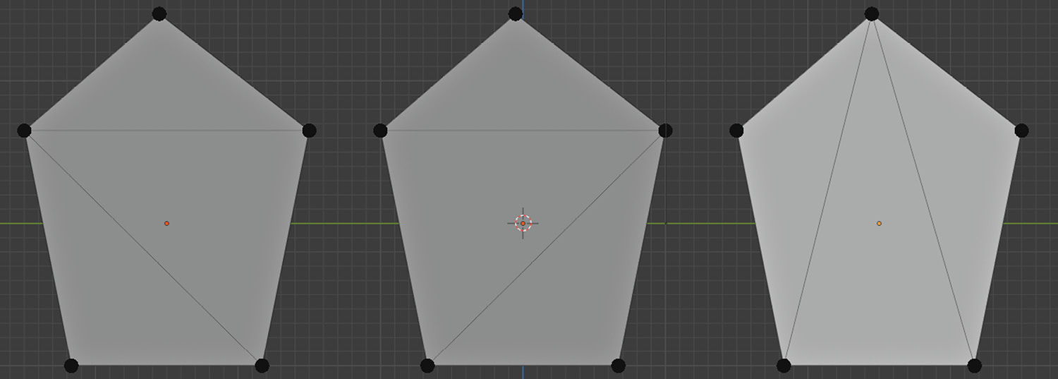
Figure 6.1 – The triangulation result could be different for the same polygon
Thus, when you leave the triangulation task to the GPU, it makes assumptions about which vertices should connect. Keep in mind that we don’t want all the vertices to be connected, just the minimum number without creating any overlapping edges. So, for a pentagon, we can have five different triangulation cases. That’s a lot of guesswork for a GPU to know which one you’d prefer.
In Chapter 5, Setting Up Animation and Rigging, we discussed the role of topology, which mainly involves distributing edges and faces. If you studied the content in more detail by following the URLs provided in that chapter, you must have come across the notion of edge flow. If you have a rig that’s supposed to bend the model, you’ll want the edges to follow a line as straight as possible into the bent part. Consequently, it pays off to do your own triangulation to create a smooth edge flow or simply avoid any n-gons altogether.
N-gons usually occur when you do loop cuts, but you can also create them accidentally while editing other parts of your model without noticing it. A quick way to get rid of them, if you can’t avoid creating them, is to connect some of the vertices manually. You’ll find an object with five vertices, hence five edges sharing one face, inside the Ngons.blend file in the Start folder. That’s a 5-gon or a pentagon right there. Let’s see how we can fix it:
- Select the vertex at the top and one of the bottom vertices by holding Shift.
- Press J to trigger the Connect Vertex Path operation.
This may not look much different, but you have added one more face by connecting those two vertices. You must have two faces now. Let’s do something similar but pay attention to the number of faces shown on the right-hand side of the status bar. It should show Faces: 0/3 after you do the following:
- Select the vertex at the top and then the other bottom vertex by holding Shift.
- Press J to connect these two vertices.
After your previous edits, your pentagon will look like the third case in Figure 6.1. If you fancy it, you can undo your steps and connect another set of vertices. Which vertices you should connect depends on your situation, so there is no hard rule.
Despite the number of vertices staying the same, you now have two more faces and two more edges compared to the initial state. Speaking of the initial conditions, take a look at Tris in the status bar, and reopen Ngons.blend without saving; you’ll see that Tris in the status bar will still show 3. That’s because the GPU was implicitly triangulating the pentagon. You have now explicitly defined which vertices should connect, hence where the edges and faces should be.
Now that we have covered why and when it is important to fix the n-gons, here is a situation where you may not need to be concerned about n-gons at all. If you have a model that you know, for sure, you won’t be animating (hence there is no rigging that would require a clean topology), then you can do without fixing your n-gons. Professionals insist on fixing n-gons because chances are the models will be animated, so they do it just in case. However, you now know you also have a choice.
Setting origin points
An origin point is a point where all your transformations start. This often sounds a bit technical, so sometimes, it’s easier to think of it as the center of gravity. However, that might be a misleading definition because you can change the origin point for your models, whereas the center of gravity doesn’t normally change in real life.
We must open Origins.blend in the Start folder to get to the bottom of origin points. For now, let’s just look at the following screenshot:
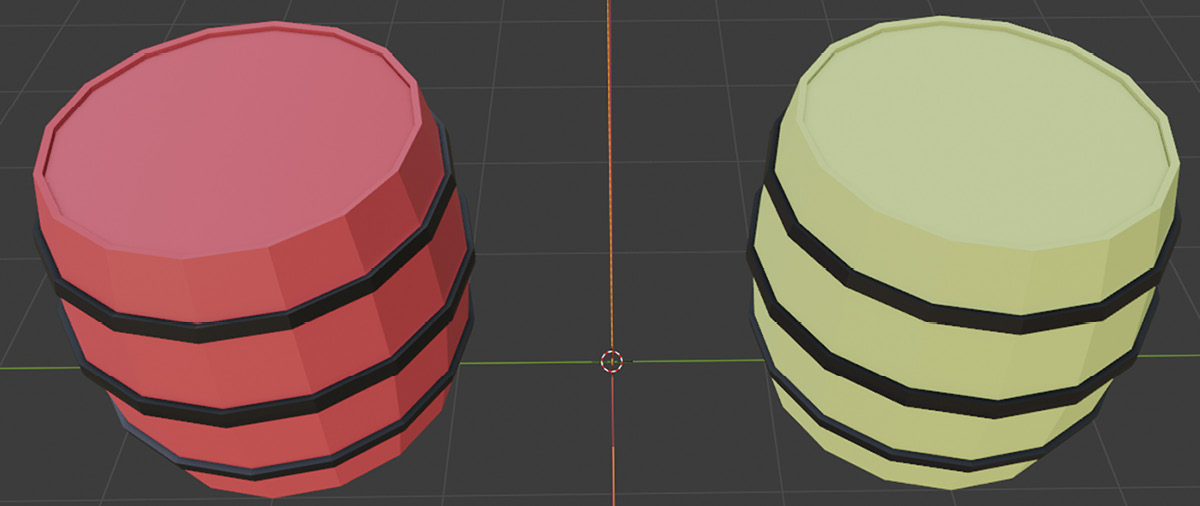
Figure 6.2 – These two barrels look very similar, but are they?
The Origins.blend file will contain two barrels, one painted in red and another painted in yellow. If you select the red and yellow barrels back and forth, you’ll notice that an orange dot inside the outlined shape is in a different spot for each barrel. To get a better view of what’s going on, you can switch to the Right Orthographic view by pressing 3 and observing that orange dot after you select either barrel. That dot is the origin point.
Follow these steps to understand the role of the origin point:
- Select the red barrel.
- Press R to rotate and then X to constrain the rotation axis. Then, type -45.
- Select the yellow barrel.
- Press R to rotate and then X to constrain the rotation axis. Then, type 45.
The values for the rotation were carefully selected to make these barrels tilt toward each other so that you can compare their final conditions. Although both barrels rotated the same amount, the yellow barrel seems to have leaned closer to the ground. To compare your results, you can refer to Origins-1.blend in the Finish folder, or take a look at the following screenshot:
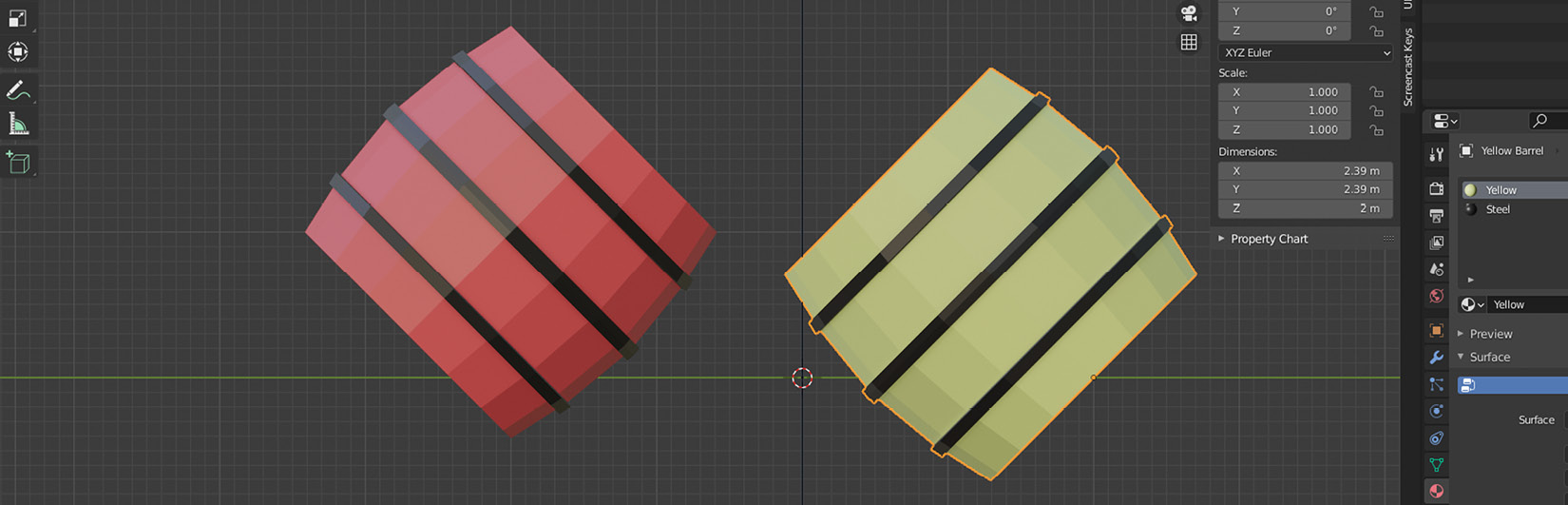
Figure 6.3 – Barrels rotated toward each other by the same amount around their origin point
Did you realize that both barrels were rotating around their origin point? We could take this a step further and place the origin point at the bottom of one of the planks of the barrel’s body.
To make the barrel look like it’s leaning around a more accurate pivot point, follow these steps:
- Select the yellow barrel and press Alt + R to reset the rotation.
- Go to Edit Mode and select the left-most vertex. Alternatively, hold down the middle mouse button to get a better view of the vertex that goes along the green Y axis.
We still need to complete a few more steps to set the new origin, but the following screenshot should help you find this mysterious vertex:
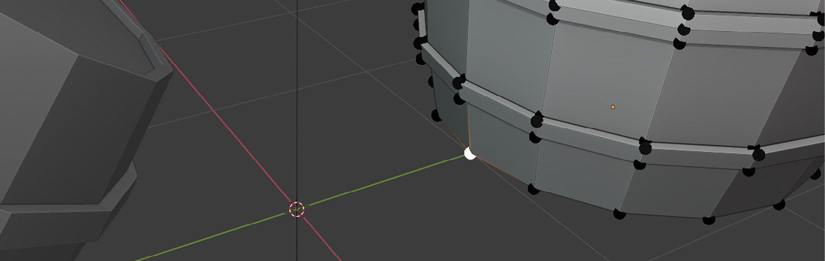
Figure 6.4 – This vertex will be the new origin point soon
In Chapter 1, Creating Low-Poly Models, we briefly mentioned 3D cursors. You might be used to working with other types of cursors, such as the ones you often see in a word processor or code editor. They usually blink regularly and place the character right there when you type on the keyboard.
Well, this is a 3D cursor, and it doesn’t blink, but its role is similar. You can see it sitting where the X and Y axes meet in the preceding screenshot. To move that 3D cursor to the selected vertex and set a new origin, do the following:
- Press Shift + S. A radial menu will appear and offer many choices for snapping.
- Select Cursor to Selected or press 2.
The choice we selected snapped the 3D cursor to the vertex you have selected. We are not quite done with moving the origin yet since we haven’t told the barrel object where the new origin is. For that, we need to do the following:
- Go back to Object Mode.
- Right-click and choose Origin to 3D Cursor under Set Origin.
This will move the origin point of the barrel to the 3D cursor. That’s why we had to move the 3D cursor to a specific vertex so that we could designate it as a new origin. The following screenshot shows the context menu and where to find the origin options:
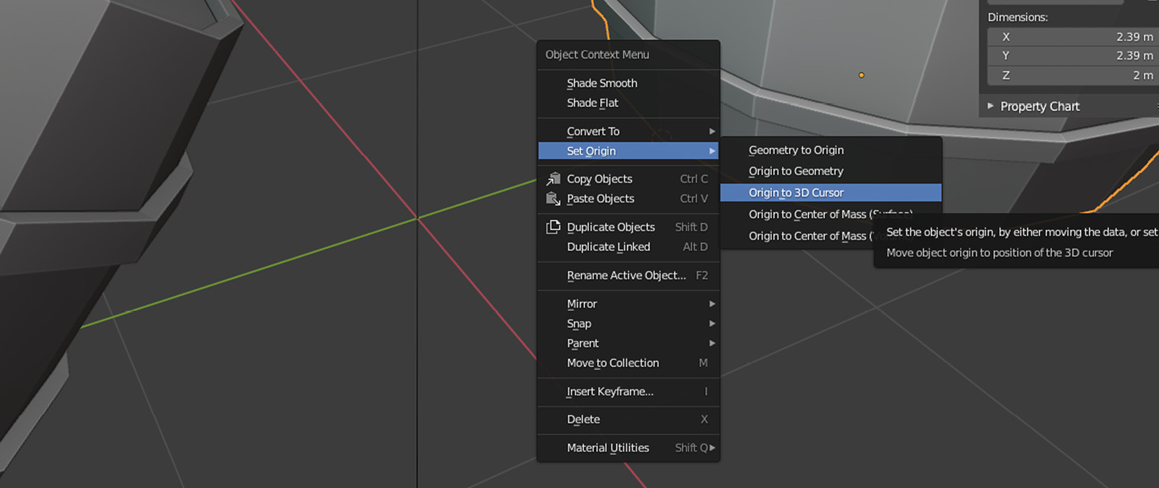
Figure 6.5 – Setting the origin is a common operation, so it’s part of the context menu
You can open Origins-2.blend in the Finish folder to see the yellow barrel applied with the same rotation from before, but, this time, the rotation is happening around a different origin point.
In the end, in most situations, setting a new origin point involves going into Edit Mode to select where you’ll move the origin, then shifting the 3D cursor to this point temporarily so that you can set the origin in Object Mode. You could, of course, designate a completely arbitrary point outside the volume of your objects as their origin too.
An origin point will be used in Godot later, similar to Blender. If you set the origin point for a door at one of the hinges in Blender, rotating that door in Godot around the Y axis will use the hinge to revolve the door so that everything will look correctly calculated and adjusted.
Applying rotation and scale
This is, by far, one of the most important topics to take care of before you export your Blender asset. It has been mentioned several times in this book that looks can be deceiving. Applying rotation and scale falls under the false looks category. Let’s understand this issue better by opening Scale.blend in the Start folder.
You should see two cubes, as shown in the following screenshot, that are on either side of the X axis. Also, the Transform panel is already expanded for you to look at the transform these cubes have, and you can use the N shortcut to toggle it on and off in the future. An object’s transform is defined by its location, rotation, scale, and dimensions, but we’re only interested in rotation and scale.
Those two cubes sure look the same, except one is green and the other is red, but they also are different in another way. Start by selecting the red cube, then the green cube. Do this a bunch of times while paying attention to what’s changing in the Transform panel.
The following screenshot also shows you where you can find this panel:
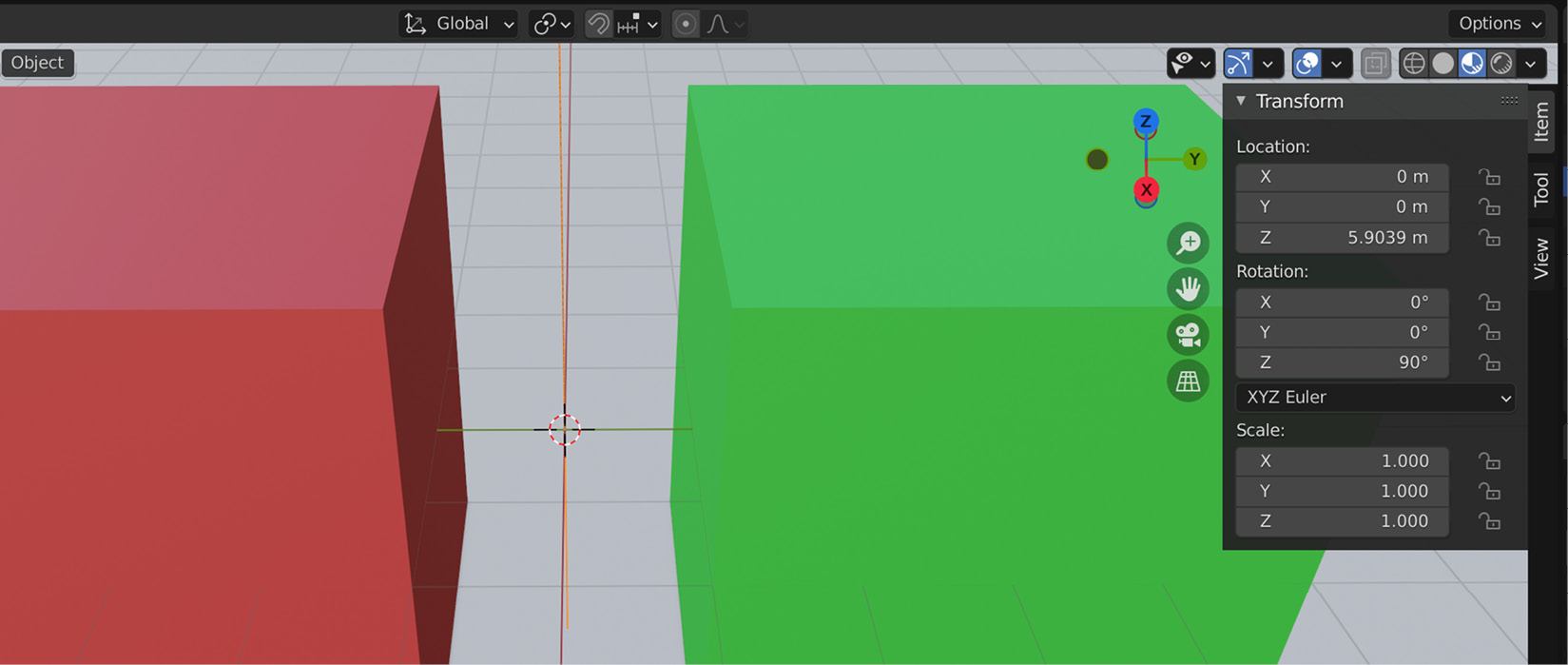
Figure 6.6 – The Transform panel is in the top-right corner of the 3D Viewport area
Both cubes’ dimensions are 4 x 4 x 4 meters. Their location, individually, indicates where they are supposed to be. So far, so good. The scale and rotation values tell us a different story, though. So, how did this happen? Simply, the author of this file did what even the most advanced users sometimes do: they started modifying the properties of the red cube in Object Mode, whereas the green cube received its changes in Edit Mode.
Making such a simple mistake is quite common, and in fact, it may not even be considered a mistake because sometimes, you just want to select things and start editing without worrying too much about which mode the object is in. However, once you are done, you need to reset the rotation and scale back to 1 for game engines to do their job. This is one of the most common things people fix before they deploy their models to any game engine, so the situation is export format-agnostic. So, if you want to export your files as FBX so that you can import them into Unity, you’ll still need to do this.
Luckily, the fix is simple. You can select the object that has a transform you want to fix, then press Ctrl + A. A popup menu will ask you what properties you would like to apply, which will reset the object’s transform for the selected property. The fifth option, Rotation & Scale, is what we are looking for. When you trigger that option, you’ll see that the red cube’s rotation and scale values will reset to their default values.
After you import your models into Godot Engine, or another game engine for that matter, when your models behave in a weird way, such as some faces are missing or the animations are acting up, often, the rotation and scale are the culprits. So, make sure they are zeroed in before you export.
Naming things properly
Phil Karlton, who worked at Netscape, now a disbanded company that paved the way for browsing the internet with their web browser Netscape Navigator, famously uttered the following words:
This quote is often passed around as a joke but, like most jokes, there is a hint of truth. If not in cache invalidation, there certainly is for naming things. Seeing meaningful names will make it easier for the future you or for a colleague to remember and understand what was done before.
When you start with primitive objects, Blender will label them for what they are: cube, plane, light, and so on. Your models will eventually get more complex at some point, and they will most likely have parts that will no longer look like a cube. So, keeping the original names will make your life harder at some point, both while working in Blender and Godot and even in another application if you use your exported assets.
So, give your objects names!
Wrapping up
You’ll likely do some of these fixes more regularly than others. It’s easy to forget to apply transformations, for instance, but it’s an easy fix. Changing the origin point is a useful method during the modeling process for you to scale and rotate things smartly. In the end, you’ll most likely leave it at its last position, so it’s OK to come back to Blender to set it to its permanent position for your game to apply correct transformations later. Peruse the list of topics presented in this section as often as you need, and you’ll develop a habit over time.
If you would like to practice the notions presented so far, we have prepared a Fix-Me.blend file in the Start folder. We wanted to design a simple heavyweight very fast, so that effort left the object with its default name. Also, its rotation and scale values look premature. While you are at it, you can also fix the n-gon and move the origin point to a different corner.
At some point, you’ll eventually want to transfer your files to Godot. To that end, we often use exchange formats when both applications don’t share a common file format. That’ll be the case for us since we can’t directly open and process Blender files in Godot. Therefore, we will discover a file format, glTF, that’s been gaining popularity in recent years. It will help us transfer our work in Blender to Godot Engine.
Exploring glTF and other export formats
Compatibility between different software has always been a delicate matter. Actually, with most physical things, it is still a common problem even in modern life. Electric plugs and sockets, for example, come in different shapes and sizes in many countries. At the time of writing, 15 plug types are used worldwide according to https://www.worldstandards.eu/electricity/plugs-and-sockets/. You may want to make sure your devices are compatible before you leave home for a long distance.
It seems there is no consensus on what type of plug is best. Similarly, when it comes to exchanging data between different pieces of software, there are a plethora of options you could choose from. So, in the next few sections, we will discuss different types of export formats to see why we should choose glTF over other formats and how gITF is the better choice. Then, we will discuss gITF in detail.
Comparing gITF with other formats
Out of the dozen file formats Blender employs in its arsenal of export options, we’ll focus on glTF because it works well with Godot Engine. That being said, let’s present a few popularly used formats such as Collada, FBX, and OBJ first before we get to the good stuff:
- Collada: This format, which has DAE as its file extension, was conceived to be a data exchange format between 3D applications. This sounds promising at first, but although a game engine could be considered a 3D application, it’s not – at least regarding the way this format was intended to be used. Collada was designed more for exchanging information between more classic 3D authoring programs such as Blender, Studio Max, Maya, and others, but not so much for game engines.
It’s based on XML, so you can open a Collada file with a text editor. This format fell out of favor over time since the specifications were ambiguous and have been incorrectly interpreted and implemented. For earlier versions of Godot, especially before glTF was out, Collada used to be the preferred file type. Now, we have glTF as a much better option.
- FBX: This is a proprietary file format offered by Autodesk. Since there are no official format specifications available to the public, and FBX’s license doesn’t let open source projects use FBX, even if the specifications are privately acquired, there have been attempts to reverse-engineer this format to write exporters for it. That’s how Blender implemented the FBX exporter to the best of their guesses.
Additionally, Godot engineers did their best to implement an FBX importer. Nevertheless, all this has been a bit of guesswork since the specifications are not open. To prevent hidden surprises and for a more seamless transition over to Godot, we won’t use this format.
- OBJ: This is a simple plain text data format created by Wavefront Technologies. So, yes, this too can be opened with a text editor. Plain text data formats offer ease of editing, but since they are not compressed files, it’s often slow to parse and import them. OBJ suffers from a different problem, though. It can’t store animations and light sources, but it’s a simple and good format to primarily hold mesh information.
This also means it doesn’t store material and texture information. To achieve that, you need to create an MTL file alongside the OBJ file you are creating. OBJ is an old and reliable format and is considered an industry standard, but it’s not cut out for modern game engines.
Now that we have seen which formats we won’t use, let’s focus on what makes glTF a better choice for us. We’ll do this by providing a brief history of glTF, followed by presenting which settings we must choose in Blender’s export settings for our efforts.
Introducing glTF
Short for Graphics Language Transmission Format, glTF was first released in 2015 by Khronos Group, a member-driven non-profit consortium founded and empowered by many big corporations. Not every member corporation is in the digital content creation business, but they have a stake in the consortium because Khronos maintains other standards such as OpenGL and WebGL, two well-known graphics APIs that serve many industries.
The discussion about the reliability of a file format might be important at this point, especially if you are planning to reduce long-term maintenance problems and costs. For example, how many of us remember the early internet days’ video file formats? Just to name a few, there was RealMedia, QuickTime, DivX, and many others, for which we’d have to install codecs, plugins, and more just to watch a few cat videos. Our desire to watch our furry companions never changed, thankfully.
Nevertheless, things coalesce eventually, and it gives way to better and more maintainable file formats. Hence, guidance from a standards group such as Khronos is a good thing since they ensure that the file format receives proper attention and stays up to date with the ever-changing needs of the industry. glTF is one of these healthy cases, and the fact that it’s open source and many corporations would like to support it is a good sign. It would be a terrible day if you had a bunch of assets sitting in your game engine one day and you learned that you can no longer export in that file type. What would you do with the existing assets – throw them out and convert them into a new format?
Now that we’ve had a brief history lesson, let’s get to know the relevant parts for us. We’ll utilize Blender’s glTF implementation, which supports the following features:
- Meshes
- Materials (Principled BSDF) and Shadeless (Unlit)
- Textures
- Cameras
- Punctual lights (point, spot, and directional)
- Extensions
- Custom properties
- Animation (keyframe, shape key, and skinning)
We won’t use even half of this feature set. We discussed why we won’t fuss over cameras and lights in Chapter 4, Adjusting Cameras and Lights, for we’ll set them up when we are building our game in Godot.
A quick note on what Blender’s glTF exporter does with meshes: n-gons will automatically be triangulated. So, it won’t be left to the GPU’s mercy. The Deciding what to do with n-gons section of this chapter covered how to split faces into triangles if you need a reminder on how to triangulate manually.
Let’s finish this section off by presenting three different flavors of glTF you can use. To access the list of variations, you’ve got to choose the glTF 2.0 (.glb/.gltf) option after expanding the Export menu item in the File menu. In the pop-up screen that appears, you’ll see a Format dropdown on the right-hand side, which will show the variations that you can see in the following screenshot:
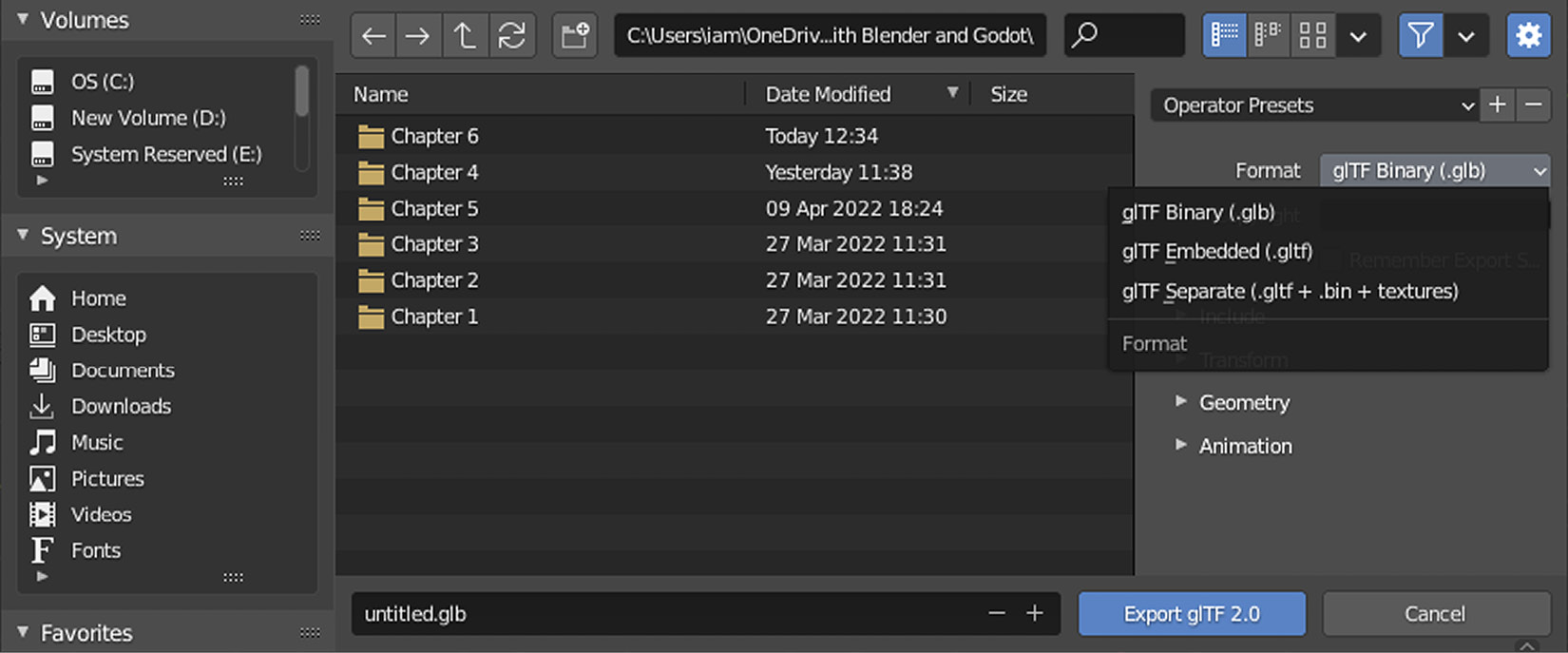
Figure 6.7 – Three possible variations you can use for a glTF export
These format variations will work the same, regardless of what settings you choose. We’ll cover these in the next section, so first, let’s get to know what each variation does:
- glTF Binary: This is the default option that will create a file with the .glb file extension. We’ll use this variation throughout this book, and you’ll most likely use it in your workflow as well since it stores everything you need in one file, and it’s compressed. This makes it easy to share with other people and transfer over the internet.
- glTF Embedded: This is similar to the binary option, except it converts all the data into a JSON text format, similar to some of the other file formats we discussed earlier in this chapter. This will result in a file with the .gltf file extension and will make the file size larger but open to easy modifications with text editors if you wish. There is no practical reason why we should choose this variation over the binary option.
- glTF Separate: This last option will create many files: one file with the .gltf file extension, similar to the one you get if you choose the Embedded option, then a .bin file that holds the data, and optionally all the textures you’ve used with either .jpg or .png extensions. So, it likes to keep things separate. Since the data is stored in the .bin file, it keeps the .gltf portion smaller, unlike the Embedded variation. Nevertheless, there is still no practical reason for us to prefer this format. Also, if you had to send your model away, you’d have to remember to send all the separate parts too.
Regardless of the variation, the importing software will follow the glTF instructions set by the Khronos standards group to create your models, materials, animation, and others. So, choosing a variety may only be needed when it’s necessary and for more advanced cases. For our work in this book, the binary variation will satisfy our needs.
Now that we know which variation is best for us, we must reflect on our own needs so that we can tick the right options in the exporter’s interface. That’s what we’ll cover in the next section.
Deciding what to export
Not everything in your scene should be exported. For example, as mentioned previously, we will create the camera and light conditions for the game world inside Godot Engine. So, once that’s done, there is no need to keep a camera and light object in your Blender scene. However, they might be useful for you to take test renders to get a better feeling for your scene without constantly exporting your models to Godot. In this section, we’ll determine the better export candidates and how to use the export settings to facilitate that.
The export options are categorized, and we’ll go through some of the options where appropriate. We’ll do this by discussing how these options relate to the objects you have in your scene. Note that the export window is separate, so you don’t need to close it before you select your objects in the scene. You can go back and forth between these two windows during this effort.
Include
Although the category’s title is straightforward, the implications of what to include might be very important. By default, none of the options in this category are selected. So, it’s up to your workflow. There are two groups you will see when you expand this section:
- Limit to: This is where you select what you want to include specifically as a mesh. We’ll discuss this in more detail in the upcoming paragraphs.
- Data: Anything that is not a mesh could be considered data. For example, cameras and lights are not physical objects with mesh information but complementary tools that help you render a scene. We’ll leave everything under here unchecked.
By default, all the options for both groups come unchecked. We’ve already said to leave the data untouched, but out of the four choices you can select under the Limit to section, the most important one is Selected Objects.
If you leave this unchecked, then Blender will include everything in your scene. This means that at the end of our exercise in the Setting origin points section, when we had two barrels, Blender would try to export both of those barrels. That’s not something you’d most likely want. Chances are you’d want to design a barrel and export only that to Godot. So, we’ve got to have the Selected Objects export option checked first. Then, we need to go into our scene and select the object(s) we want to export. There might be some inconvenience in doing this so easily, though.
We have been designing relatively small models with a few different parts. The greatest number of separate parts we designed was with the three distinct parts of a barrel. In the future, during your work, if you happen to have a dozen or more parts in your Blender scene, it will quickly get tedious to select all these parts again and again before you hit the export button. If only we had an option that would not export the camera and light but what we deem as important so that we can have the best of both worlds…
That option is Visible Objects. Start by deselecting Selected Objects and keep the Visible Objects option on. For this option to work for us, we need to hide the camera and light objects so that they are no longer considered candidate objects to the exporter. You can do that by clicking the eye icon in the Outliner area for any object you don’t want to export.
In the end, you have a mixed bag of solutions when it comes to what to include in your export. There are no right or wrong answers here, but you must choose what’s efficient for you.
Transform
We’ll cover this category for the sake of completeness. You’ll rarely touch this category since it has one and only one option, which is on by default. Let’s explain why, though, and learn what +Y Up means.
In Blender, the three axes or the coordinate system, XYZ, is set up, so the Z axis defines how tall or elevated an object is. In some other applications, such as Godot Engine, the Y axis is used as the going up axis. So, the higher the Y position of an object is in Godot Engine, the higher it sits in the game world. Therefore, this Blender export option converts Blender’s Z axis into Godot’s Y axis. It’s a handy thing, so you don’t have to arbitrarily rotate your models so that they match the correct direction.
Geometry
We’ll leave most of the options under this category as-is and only discuss what matters to us. These options are as follows:
- Apply Modifiers: We first discovered modifiers in Chapter 1, Creating Low-Poly Models. We used a few that helped us model a barrel in no time. The fact that you can stack modifiers and change the order of operation is great. However, they are temporary additions to the core objects. So, unless you turn this option on in the export settings, the base object will be exported without any modifiers applied. This will make your objects look quite awkward and primitive in Godot.
- Materials: The default status of this option is to export all your materials. This might be a good thing for a beginner or quick results. When we discuss materials again when we cover Godot, and should you decide to make your own materials in Godot, you may want to pick the No Export choice so that they are no longer included in the resulting file.
In more advanced export scenarios, you may want to enable the Loose Edges and Loose Points options as well, so you can keep the loose geometry as a part of the exported file.
Animation
We won’t change any of the default options in this category. We discussed how to create multiple animations in the Getting animations ready for Godot section of Chapter 5, Setting Up Animation and Rigging. The default settings will take care of converting the animations – more specifically, actions.
Creating presets
If you find yourself turning some of the options on and off under certain scenarios and memorizing the correct combination is becoming hard or monotonous, you can create a preset of export options. The top part of the export options has a dropdown with two buttons next to it. Using that area, you can create your own presets – perhaps one for a selected objects case and another one for a visible objects case.
Choosing the correct export options depends on the different conditions your project requires. So, you must experiment and find what works best for you. At some point, you’ll import the result into Godot Engine to visualize the glTF file. However, that might be a lot of work to go in between two applications if you want to get a quick feeling about your creation. The following are two options you can use to preview glTF files:
- glTF Viewer at https://gltf-viewer.donmccurdy.com/
- Microsoft 3D Viewer
This concludes the investigation of the export options that are relevant to our case. Let’s see what other discoveries you have made so far.
Summary
This chapter was mainly about making your work compatible with Godot Engine. To that end, we needed to go over a few different topics.
Firstly, we wanted to make sure our models had received the correct final touches. This involved getting rid of n-gons and converting these polygons into more manageable and ideal triangular faces. After that, you learned how to set origin points for your models, which may also be helpful during the modeling phase. Making transformations permanent is essential, so that’s something to remember if your models, especially during animations, behave awkwardly. Then, we looked at the idea of naming things meaningfully. This is something you’ll eventually find yourself needing more and more down the line when you have more experience.
Then, out of the many formats Blender offers for exporting assets, we evaluated a few, such as Collada, FBX, and OBJ. During that effort, we presented that glTF has become the de facto format for communicating between Blender and Godot. Lastly, we discovered some options for the glTF exporter and presented a few likely scenarios you may wish to employ. Finally, you learned how to store the export options that work best for you.
Now, we’re ready to start importing our Blender assets into Godot. That’s exactly what we’ll do in the next chapter. In a real-life scenario, chances are you’ll be conducting the operations presented in this and the next chapter quite often in almost every phase of your game development journey. Let’s give you a few more useful resources before we move on.
Further reading
Khronos Group is a maintainer of many other standards we use day-to-day. This is thanks to their impressive list of members, which you can view at https://www.khronos.org/members/list.
We primarily used their glTF standard. The following links provide more technical information about it:
- https://docs.fileformat.com/3d/gltf/
- https://docs.fileformat.com/3d/glb/
- https://www.marxentlabs.com/gltf-files/
- https://www.marxentlabs.com/glb-files/
Thanks to its nifty specifications, the glTF exchange format has been gaining popularity not only in the gaming industry but in other industries as well. Here is NASA’s famous Voyager spacecraft in all its glory: https://solarsystem.nasa.gov/resources/2340/voyager-3d-model/.
You may have come across websites where Collada is still used for Godot projects. Perhaps you already have access to a large repository of Collada files. If you would like to give it a try, but with a bit more finesse, here is a GitHub repository that can help you: https://github.com/godotengine/collada-exporter.
Last but not least, cleaning up your models and keeping them export-ready will be an ongoing task. Blender’s user manual has a page on many tools and methods you can use to help you in your efforts: https://docs.blender.org/manual/en/2.93/modeling/meshes/editing/mesh/cleanup.html.