
1
Creating Low-Poly Models
Blender is a sophisticated program that has gone through a lot of iterations to get to the point where it is now. More and more professionals in different industries are investigating it as an alternative to other well-known 3D applications out there, such as Maya, 3ds Max, ZBrush, and Modo. Also, Blender happens to be a good starting point for hobbyists and people who can’t afford the licensing fees of the aforementioned software. Additionally, Blender has a helpful and large community that creates courses and tutorials. Blender Conference (BCON) is an annual event where you can meet professionals.
An important decision you must make before you start creating 3D content with any type of software is where you are going to use your assets – this directly affects the style and workflow you will follow to accomplish the task. One type of workflow is called low-poly modeling, with which you create 3D assets that have a minimum number of details.
In this chapter, we’ll discuss why low-poly modeling might be beneficial compared to other workflows. Following the advantages, you’ll learn how to create low-poly assets using different techniques. We’ll conclude this chapter by introducing a few modifiers that might prove indispensable.
In this chapter, we will cover the following main topics:
- Understanding low-poly models
- Advantages of low-poly models
- Creating a low-poly barrel
- Automating with modifiers
Technical requirements
To follow the instructions in the chapters that involve Blender, you must install the necessary software on your computer. The Blender website – more specifically, their download page at https://www.blender.org/download/ – contains instructions and links for your platform. In this book, we are using Blender 2.93. Although version 3.0 will offer interesting and exciting options to new and existing Blender users, the current version is more than capable of creating game assets for your projects and the topics covered in this book.
This book uses GitHub to store the code that will be used in the Godot chapters. However, the same repository (https://github.com/PacktPublishing/Game-Development-with-Blender-and-Godot) also hosts the Blender files used throughout the relevant chapters. Where it makes sense, the repository will be structured with Start and Finish folders inside each specific chapter for you to start over or compare your work as you make progress.
Understanding low-poly models
Simply put, a 3D model is considered to be low-poly when it uses the minimum number of polygons to make its most characteristic features, mainly its look and feel. However, let’s take a look at them in a little more detail.
In real-time applications such as game engines, your computer’s central processing unit (CPU) and graphics processing unit (GPU) are responsible for processing the visual information you see on the screen. In the last two decades, the trend has been leaning heavily toward the GPU side since GPUs are dedicated to one main task: processing graphics.
GPUs have an advantage over CPUs in that regard, and they don’t discriminate between 2D and 3D graphics. However, whereas 2D images contain pixel information, 3D objects are represented by data that holds the necessary coordinate information that defines the object.
Although a cube is still a bunch of pixels after it is rendered on your screen, the data that defines the cube is essentially eight points, which are called vertices. For demonstration purposes, in the following screenshot, Blender’s vertex size setting has been changed so that you can see where those vertices are more easily:
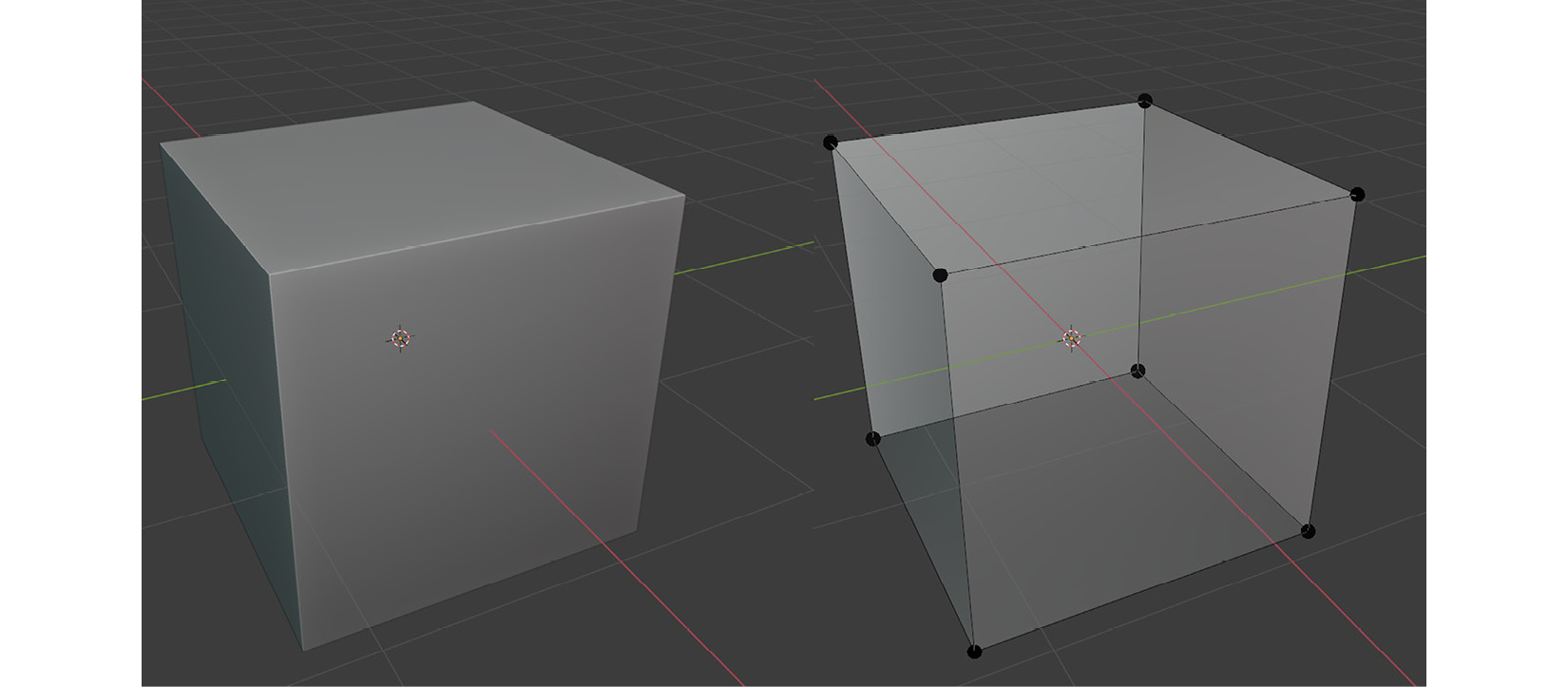
Figure 1.1 – The eight vertices of a cube
Both cubes are the same object, but it’s possible to render the same eight vertices and their relationship with each other in two different ways: one that looks like a solid object (on the left) and another that looks transparent (on the right). So, keep in mind that vertices are data points that define the shape of the object, not how it looks. Later in this chapter, you’ll learn how to make objects look different, similar to what’s shown in the preceding screenshot.
Before we discuss what makes a model low-poly, we must understand a few other essential parts. You’ve already seen that the vertex is the most crucial component, but there are two more concepts you must be aware of:
- Edge
- Face
Let’s see how these two relate to a vertex. By doing so, we’ll be on our way to understanding what makes a model low-poly.
Parts of a 3D model
An edge is what connects two vertices. It’s as simple as that. If you look at Figure 1.1 again, you’ll see that not all the vertices are connected. However, when they are connected, it’s called an edge and depicted by Blender with a straight line going from one vertex to the other.
A face, as you may have deduced, is a logical outcome when you arrange vertices – or edges – in a certain pattern. For example, a cube or a six-sided die has six faces. Although Figure 1.1 makes it look like you need four edges to make a face, there is a simpler way – that is, three edges are enough to form a face. So, a triangle is the simplest face, also known as a polygon.
Low or hi, what’s the difference?
When you are designing a model, you are creating polygons. The density of the polygons in a model is what determines whether a model can be considered low-poly. The following figure displays one low-poly and one high-poly work sample, courtesy of Sketchfab users MohammadRezae and DJS_05:
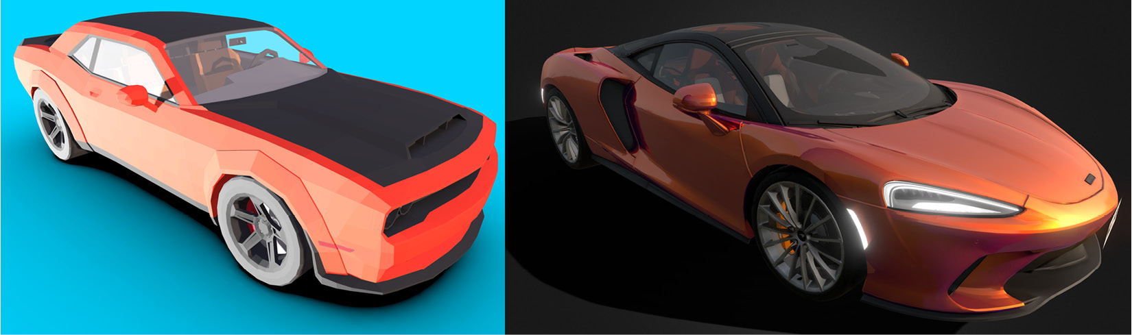
Figure 1.2 – An example of a low-poly versus high-poly model
You can find a lot of examples of different polygon counts on websites such as Sketchfab.
In the industry, if you are asking for a model to be designed for you, you may want to mention that you want it done in low-poly form. It’s often agreed that if you don’t mention this, people will assume it’s going to have as many polygons as possible since you would want your models to be as detailed as possible with plenty of polygons. So, the distinction is made when you are cutting those polygons out, not when you are keeping them in.
Let’s focus on our default cube again. Is it low-poly or hi-poly? It might be both. Although we know that only eight vertices are needed to create a cube, we could have had many more vertices along the edges that connected the original corner vertices. However, it would not have made any difference in the rendered result. That being said, it would have taken the computer a lot longer to render the same visual result.
So, as mentioned previously, when your model has just enough polygons to make sense of the object you’d like to design, you’ll have a low-poly model.
Although GPUs are fast and they do a fantastic job these days of rendering millions of polygons and going low-poly may feel like you are cutting corners, there are good reasons why you may not want to have that many polygons in your project.
Advantages of low-poly models
Here is a quick list of the benefits of following a low-poly modeling practice:
- Fewer polygons
- Small file size
- A certain artistic style
- Easy to prototype
- No or minimal texturing
Working with fewer polygons certainly means fewer things to change and worry about. Shortly, you’ll learn how to create a barrel, and by the end of that exercise, your model will have close to a thousand polygons. This number may seem high at first but imagine working with a hi-poly barrel model with more than 10,000 polygons. So, if you are new to 3D modeling, low-poly modeling is a great place to start.
Should you decide to alter your models, working with a higher number of polygons will force you to be more careful. So, in essence, having fewer polygons is comforting since you will feel like you have more control over your creation. Naturally, fewer polygons will result in a smaller file size too.
The artistic style advantage is a non-technical item in the advantages list. Nevertheless, it might be an important decision. Let’s focus on Figure 1.3, for example. You’ll see why lack of detail doesn’t always mean lack of imagination:
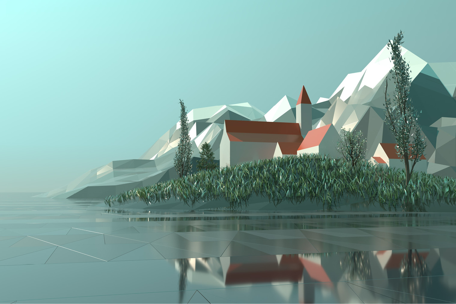
Figure 1.3 – Low-poly model landscape
Here, you can see just enough details to figure out that there is a church. Perhaps this church is looking onto a town square. The mountain tops have some snow. Is this a peaceful town that’s appealing to tourists for winter sports? Perhaps the townspeople are currently hiding in the church from a villain? Our imagination fills in the details. Whatever the case and the game genre is, the low-poly aspect of the 3D models doesn’t induce a penalty for creativity. In fact, in the last few years, we’ve seen more games with low-poly assets making headlines.
If you are working in a small game development team or if you are the only developer, you’ll sometimes want to focus on game mechanics first to see if the idea is fun. In situations like these, you’ll want to prototype objects quickly so that you can embed them into your code. When the model you are working on has a generic shape of the object you would like to design and has enough details, then you might be done. That’s why it’s a highly sought-after choice among indie developers since you can move forward quickly to the next model, then to programming your game. In essence, low-poly modeling is like prototyping but it’s a few steps more refined than placing a cone for a tree, a cylinder for a barrel, or a cube for a crate.
Last on the list is texturing. This is a process where you give a certain look and feel to your model. A sandy beach usually looks yellow. If it’s a rocky beach, then the rocks will most likely have different tones of gray. Thus, it’s about mainly applying color information to the surfaces of your model. Sometimes, this color information will be complemented by additional data such as reflectivity, metallicity, and roughness. We’ll discover all this in the next chapter.
It’s often said that most things in the computer world are a trade-off. Speed versus quality versus price is a common example where you can most likely have two out of three but not all three. Despite all the benefits a low-poly workflow provides, there are some limitations, but recognizing them will help you to find workarounds or plan ahead.
Limitations of low-poly models
If your models need to show damage such as missing parts along an edge or some chunks blown out of a face, then you need to introduce more polygons in those areas. This still won’t make it a high-poly model, but you’ve got to consider additional polygons if you fancy some dynamic details.
Also, if you decide to animate your low-poly models, you’ll need to introduce more geometry by adding more polygons in the areas where there will be bending and twisting (depending on the model you are animating).
Additionally, since there are fewer polygons, you may have to be creative with the lighting of your scene to give the illusion of detail. Although the color of the water in Figure 1.3 is the same throughout the composition, the designer used a couple of clever methods to make the scene look more interesting. First, the water’s surface looks fractured. This gives the illusion that there is some slight movement in this water’s body. Perhaps there is a gentle breeze. Second, some of those fractures have a reflective material applied. This makes the surface reflect the objects further ahead on the horizon.
We’ll look at ways to overcome these limitations in the following chapters, but for now, let’s learn how to create a few low-poly models of our own.
Creating a low-poly barrel
Every discipline comes with a few conventions for beginners. If you are learning a new programming language, writing “Hello World” to the screen is a classic example. Learning how to use 3D modeling software is no different. For example, a barrel, a potion bottle, or a donut can be started with basic shapes you are familiar with, such as a cylinder, a cone, or a torus, respectively.
In this section, you’ll learn how to design a barrel but, first, here are a few useful shortcuts that will help you navigate around and accomplish the tasks we’ll cover in this section:
- Rotate: Middle mouse button + drag mouse
- Zoom: Scroll mouse wheel forward/backward
- Move: Shift + Drag Mouse
Blender is rich with so many shortcuts and it’s possible to change them to your liking once you gain more experience. Speaking of shortcuts, this book only lists Windows shortcuts. However, when you see the Ctrl key mentioned, it’s the Command key in macOS.
When you launch Blender for the first time, you’ll be presented with some options. One important option is to decide which mouse button to use to select objects. Historically, the right mouse button was the default, but you may find this uncommon. If you dismissed that initial screen, and you are not happy with the mouse button assignment for the select operation, you can still change it by going to the Edit menu and selecting Blender Preferences. In the Keymap section, expand the Preferences section, as shown in the following screenshot; you’ll be able to change a bunch of settings, including Select with Mouse Button:
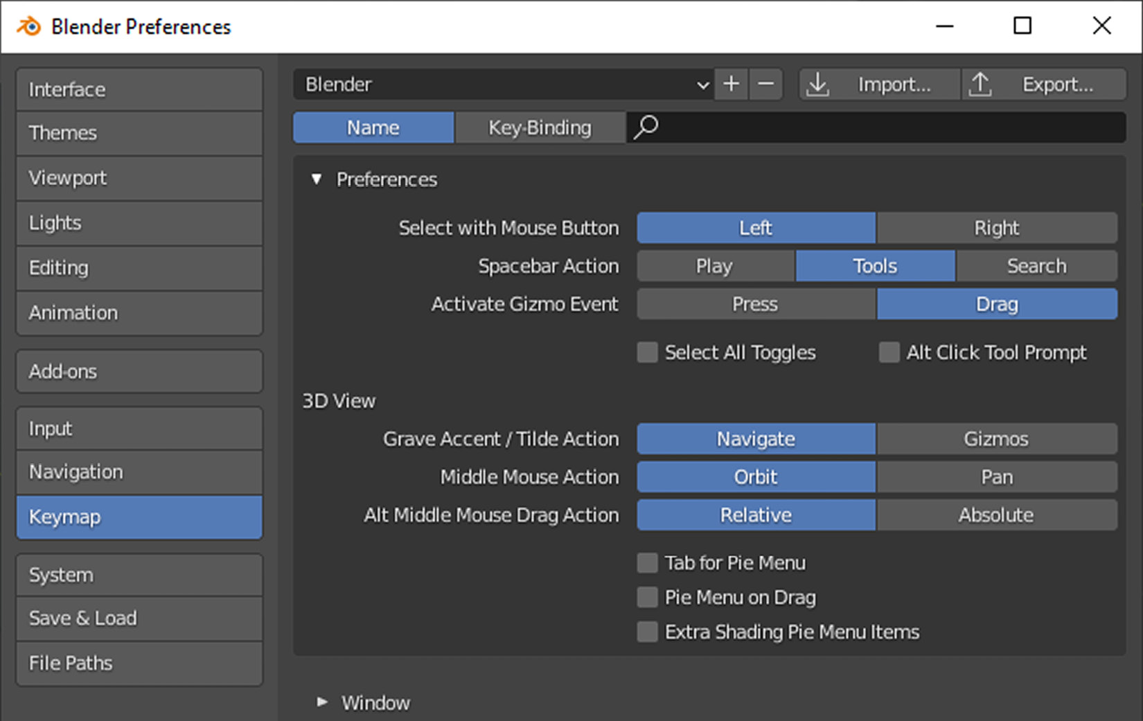
Figure 1.4 – The Preferences window of Blender
Speaking of the select button, whichever side you choose, the other side will be reserved for moving the 3D cursor to a new position. A 3D cursor is a visual marker you place in the world. When you add new elements to your scene at a particular location, or things need to align to a certain point, the 3D cursor will be that point. We’ll most likely keep the 3D cursor where it is for most exercises, but keep in mind that if the left click is for selection, then the right click is for the 3D cursor, and vice versa.
Official manual
Since this book is about game development, we’ll focus on a small and relevant portion of Blender. However, sometimes, looking at the official manual might be a good idea, especially for shortcuts. The Blender website has a decent user manual: https://docs.blender.org/manual/en/2.93/.
Modeling is a multi-step process. It involves starting with the basics and adding more details as you go. The following is what we’ll do to design a barrel:
- Start with a primitive
- Edit the model
- Shape the body
- Separate the lid
- Finish the body
- Place metal rings
- Finalize the lid
The list is merely an example workflow that highlights useful parts of Blender. When you gain more experience and find a different order to accomplish what you have in mind, you can work in whatever way works for you. However, you are likely to start with primitives.
Starting with a primitive
A new scene in Blender comes with a cube, a camera, and a light source. Since we are going to create a barrel that is more like a cylinder, we should get rid of that cube:
- Select the cube and press X on your keyboard to delete it.
- Trigger the Add menu to the left of the Object menu.
- Select Cylinder under the Mesh group.
The shortcut for adding new objects is Shift + A, which will bring up the same list of options. If you feel like deleting the other default objects, feel free to do so since you can always add them later using the Add menu. The following screenshot shows where you can find it:
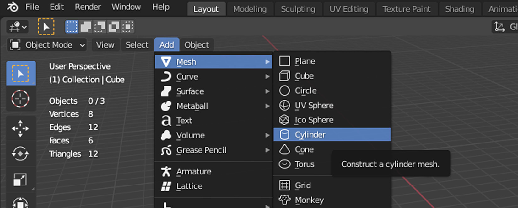
Figure 1.5 – You can add many types of primitives to your scene
Once you add the cylinder to your scene, you’ll see that the cylinder comes with a lot of side faces; 32 to be exact. For a low-poly barrel, that’s a lot of faces that could be cut down by half and you would still have a decent-looking barrel.
When you add a new object, a panel will appear at the bottom left of the screen. The title of this panel will reflect what you are currently trying to accomplish. In this case, it should display Add Cylinder. If it looks closed, click the title and it’ll expand to show the properties you can alter for your cylinder.
The default options are all fine except for the number of vertices. However, this is also a good chance to play with the values and see the changes reflect instantly. While you are doing all this, that panel may disappear if you click away from your cylinder. To bring it back, click Adjust Last Operation under the Edit menu. When you feel like you’ve got the hang of editing a new object’s properties, you can set the relevant values, as shown in the following screenshot:

Figure 1.6 – 16 faces will be enough for creating our barrel
Adding a primitive such as a cylinder has introduced a new object to your scene. You’ve changed its basic properties, such as the number of vertices. That number defines how many points are used to make up the top and bottom circles, as shown in the preceding screenshot. This was all done at the object level; hence, you’ve been working in Object Mode. Now, it’s time to dive deeper and edit the finer details of this cylinder.
Editing the model
It may seem like every time you change the value of something, you are editing the model. However, from Blender’s perspective, not all edits are the same. When you start with primitives, there are higher-level operations you can perform such as changing the number of vertices that define the general shape of the primitive. This is what you have seen and done so far – you’ve been editing objects.
When you want to have more control over the vertices, faces, and edges that make up the object, you should switch to another mode that allows you to work with these properties so that you can have much more refined control over the shape of the model.
Mac shortcuts
You can always use menus, buttons, and other interface elements to do your work, but you’ll eventually depend on shortcuts. If the shortcuts that have been mentioned so far don’t work for you, then you may want to check out Blender’s manual to find the right combination for your platform: https://docs.blender.org/manual/en/2.93/interface/keymap/introduction.html.
Select the barrel and press Tab. This will turn on Edit Mode. If you keep pressing the Tab key, you'll go back and forth between Object Mode and Edit Mode. You’ll also see that Blender’s UI is either hiding some of the buttons and menus or revealing some new ones, depending on which mode is active. This means some options are only available in a certain mode. If you are wondering where that thing you just saw disappeared, make sure you are in the right mode.
Then, in Edit Mode, press Ctrl + R to trigger Loop Cut and Slide. This is a context-sensitive operation, so if you see nothing happening, it’s because the mouse is not over a face for this tool to operate. Hover your mouse over different parts of the cylinder. You’ll see a yellow line going all the way around; the direction of the line depends on where your cursor is on that face. While still over one of the side faces, trigger your mouse wheel up twice to increase the number of cuts to 3. This is a preview of the loop cuts, but they are not part of the cylinder yet.
A loop cut will require two mouse clicks, regardless of how many loops you would like to have. With the first click, you are telling Blender that you want to introduce some cuts; in this case, 3. The second click will finalize the position of these cuts, but you can change it by moving your mouse up and down along the side of the barrel. So, in between the first and the second click, you have some freedom to position the cuts. The following screenshot shows what we are after:
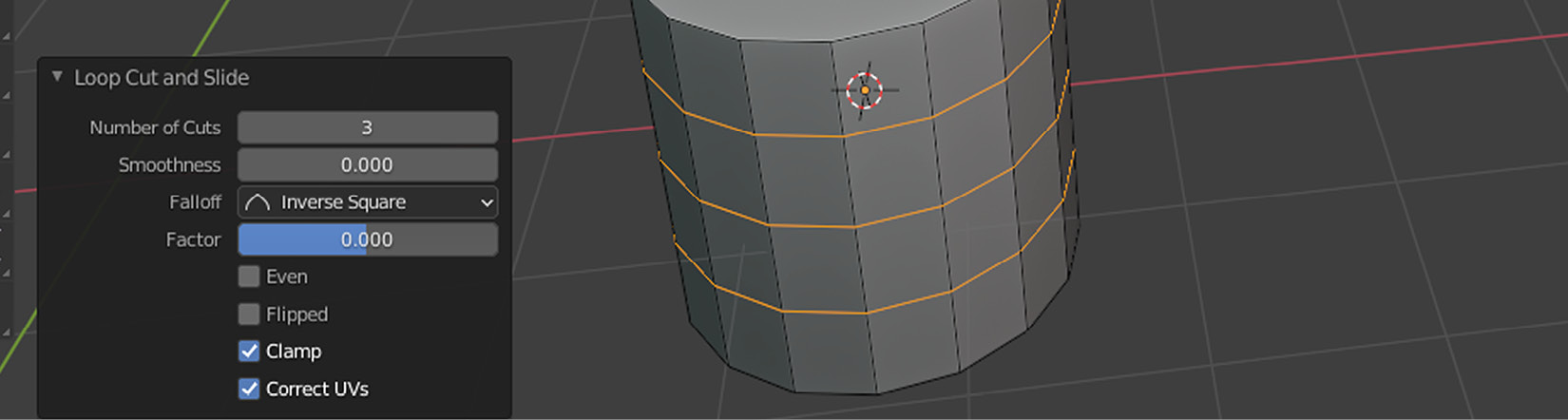
Figure 1.7 – Adding more edges with precise values
If you accidentally moved your cursor in between two clicks, which would have moved the baseline of the cuts, do not worry. Once the edges have been added, the operation’s details will be displayed so that you can fine-tune where the cuts appear in your model. The important part is to set Factor to 0 so that you have the perfect cut in the middle. If you made a last moment change before you made the cuts, you can also adjust the number of cuts.
The main reason why you switched to Edit Mode is to have more control over the shape of your objects. While still in Edit Mode, you’ll now learn how to use those loop cuts to give your object the shape of a barrel.
Shaping the body
A barrel is such a generic concept. However, we have not discussed what kind of barrel we will be working on. Technically, we are not too far off from an oil barrel since they usually look cylindrical and have two rounded-off ridges. Then, there are plastic barrels that you see in gardens for collecting rain. These tend to have a plain side with the top and bottom slightly tapered in or with the middle section slightly bulging out, depending on which way you look at it.
We’ll go for a more classic one: a wooden barrel. Since we have the basic shape, we can now start adding more details to our barrel. Two things come to mind easily. Most barrels have a few metal rings – in the middle, near the bottom, and at the top – for enduring the stress of what they are holding. Also, the lid is rarely flush with the side but more likely inset, so maybe we should treat that top part separately. Let’s start tackling all these one at a time.
Are your 3D objects looking flat?
It’d be nice to have some life in all that gray! If the default look for 3D objects feels too flat and you’d rather see the edges emphasized like you see them in pictures, here is a trick. There is a button with a down-looking icon at the top-right corner of the 3D Viewport. If you click that button and expand the Viewport Shading panel, you can switch Lighting to MatCap, and turn on both the Shadow and Cavity options in the panel. Selecting Both for the Cavity type may also be a good option. Investigate different values as you see fit so that you have an easier time working with your models.
Our barrel needs a belly. We need to make those loops we have just introduced wider to create a classic shape for the barrel. With those three edges still selected, hit S, type 1.1, and press Enter to scale it up by 10%. As usual, the last operation’s fine-tuning settings will be shown if you would like to adjust your values after finishing the action. Now, we only need to make the middle ring slightly larger.
Although we have been in Edit Mode so far, we have not investigated what you can edit. In the top-left corner of 3D Viewport next to the Edit Mode dropdown, you’ll see Vertex, Edge, and Face icons from left to right. These buttons have 1, 2, and 3 as shortcuts, respectively.
Switch to Edge edit mode by pressing the middle icon or 2. To create the belly for the barrel, you need to select and scale up all the edges that make up the middle ring, but you probably don’t want to do that for each edge one by one. Thus, we need to look at how to select an edge loop.
There are two ways to select an edge loop. The first method uses a keyboard shortcut:
- Hold the Alt key.
- Click one of the edges.
This should select all the edges that are connected to the one you’ve just clicked, as shown in the following screenshot:
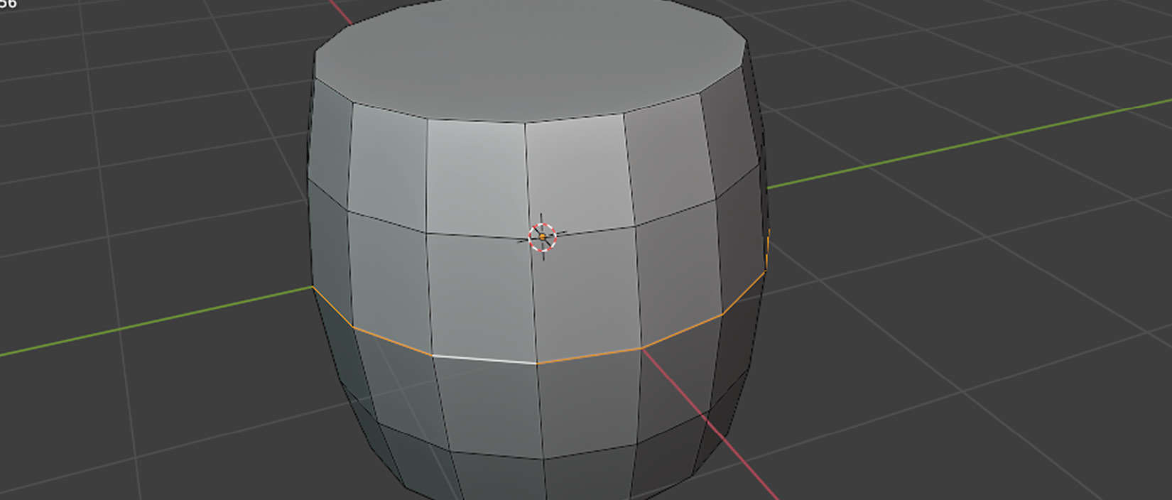
Figure 1.8 – Selecting all the edges that make a loop is easy
- Select one edge.
- Go to the Select menu.
- Expand Select Loops and choose Edge Loops.
Whichever way you do this, after you select the middle edge loop, you must do the following:
- Scale it by pressing S.
- Type 1.05.
- Hit Enter.
This should result in a classic barrel shape.
However, the top face still belongs to the cylinder. Although conceptually, a lid might be considered an essential part of a barrel, from an editing perspective, it must be treated as a separate object. Let’s learn how to separate parts to edit them individually.
Separating the lid
To create the lid, first, make sure you are still in Edit Mode. Switch to face select mode by clicking the third icon next to the Edit Mode dropdown or by pressing 3. Then, do the following:
- Select the top face.
- Press P.
- Choose Selection.
This will separate the top face and make it a separate object.
Alternatively, you can expand the Separate group under the Mesh menu. The following screenshot shows where you can find this option if you are doing the separation with the menus:
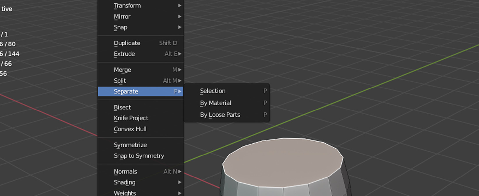
Figure 1.9 – Separating things is sometimes necessary and, in fact, helpful
Shortcuts
At this point, you must have noticed that Blender uses a lot of shortcuts. It might be difficult to learn and remember all these at the beginning. If you have a rough idea about what you’d like to do with the meshes, vertices, edges, and such, you should check out the appropriate menus near the top to see what operations are available. Pressing a shortcut key will show you just the relevant part of those menus, but investigating those menus and looking at the shortcut might be a good exercise.
For example, the P key is used to separate things, but there are three types of separation, so you’ll still have to make a final decision on the type. However, using the shortcut still takes a shorter time than expanding the menus.
Now might be a good time to introduce you to Outliner in the top-right corner. The following screenshot shows all the objects that exist in your scene right now:
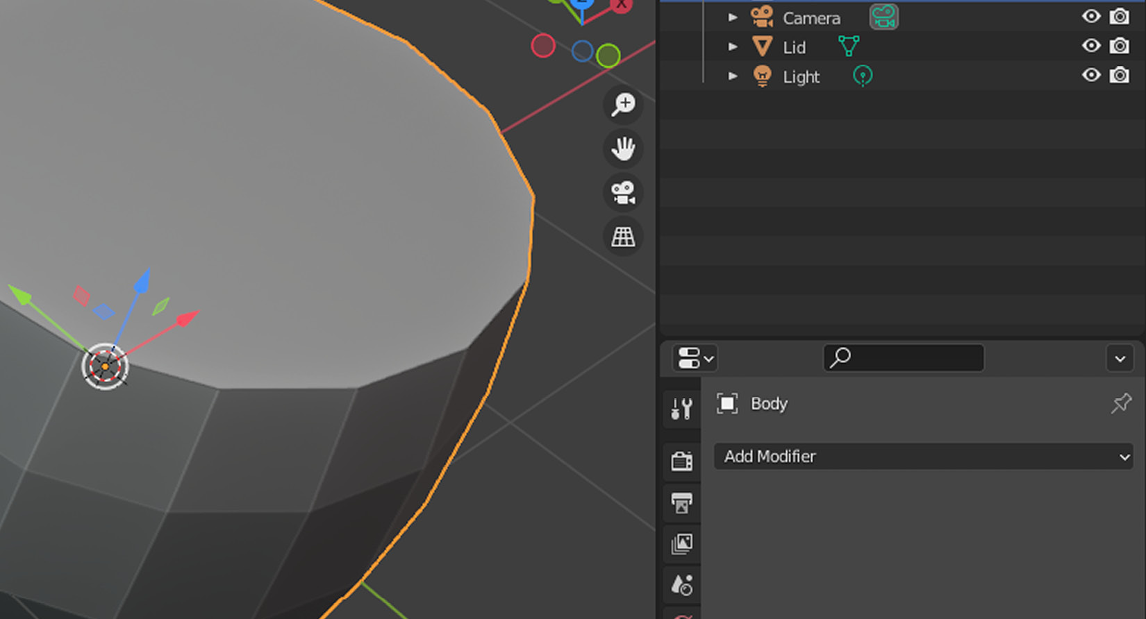
Figure 1.10 – The lid and the body should be two separate objects
You can ignore the Camera and Light objects if you kept them in your scene since we’ll discover what those two do later in this book. Over time, when you create more objects, you’ll want to label your objects so that you can easily find them in Outliner.
Let’s try it now. Double-click the label for Cylinder in Outliner and type Body. Do the same thing for Cylinder.001 and mark it as Lid. You’ll also notice that clicking labels in Outliner will select the objects in 3D Viewport and vice versa. Finally, hit that eye icon to hide the lid for now. We’ll finalize the lid once we deal with the body.
Finishing the body
What would you say is wrong or missing from the body? It looks paper-thin, doesn’t it? If only there was a way to stretch each face out or in, and fill in the gaps so it looks solid! So far, you’ve been selecting edges and faces. You can follow a similar workflow to select some faces, duplicate them, and move them around to give thickness to the body. This is tempting, but let’s find an easy way to solidify the body.
For this, you need to enable the Modifiers panel. A modifier is a tool that offers a non-destructive way to change your objects. You’ll get to read about a few of them in the Automating with modifiers section.
There is a wrench icon on the right-hand side near 3D Viewport that is going to let you add modifiers. Here are the steps you must take to give substance to the barrel’s body:
- Switch to Object Mode.
- Select the Body object.
- Open the Modifiers panel.
- Choose Solidify from the Add Modifier dropdown.
Modifiers change objects, so even if you are in Edit Mode, working with a modifier will look as if you are in Object Mode for the object you are editing. You’ll discover some of the modifiers in that dropdown list later in this chapter. For now, the following screenshot shows what the Solidify modifier is doing. Most things in Blender come with a lot of values to tweak, but you only need to change the Thickness value in the Solidify options for the time being:
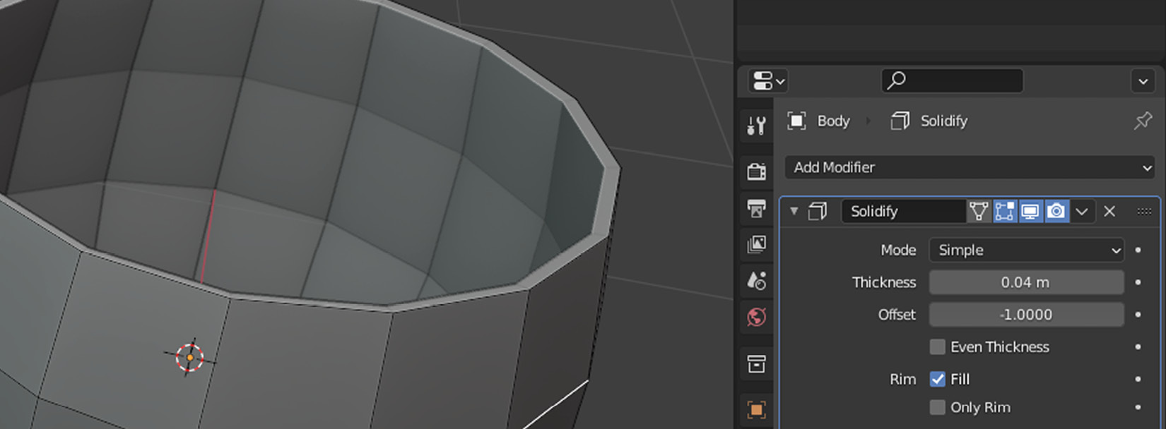
Figure 1.11 – Our barrel is starting to look more solid
How much Thickness is enough? 0.03 m or 0.04 m might be a good value. You could pick an industry-standard thickness or choose a value that looks visually appealing. Depending on the type of game you are working on or whether you are creating assets for a client, you can pick what works best for the asset.
A discussion about units
Most of the world is using the metric system these days. However, if either because it’s the default option or a matter of preference, you may have Imperial units set up in your Blender copy. Throughout this book, the Metric system will be utilized. You can find Units as a panel inside the fifth tab from the top on the right-hand side. This tab contains an icon with a cone, a sphere, and what looks like a dot.
Modifiers are very helpful, but you need to get your hands dirty sometimes. This means that there is a limit to what modifiers can do for you. For example, we now need to put metal rings around the body. There is no modifier to do this for you. Nevertheless, we can still take advantage of modifiers as we go. But, first, let’s create some metal rings.
Placing metal rings
The barrel now has some substance, but it’s missing metal rings. Creating another cylinder and sizing it up so that it looks like a ring is too much work and requires precision. There is a simpler method that takes advantage of the barrel’s geometry. You’ll be using familiar methods you’ve already seen: loop cuts, loop selection, and separation.
While in Edit Mode, create a loop cut between the bottom and the first edge loop of the body. For the other loop cut, you’ll be creating the cut in between the top edges and the loop right below it. In the end, you’ll be creating two loop cuts, as shown in the following screenshot
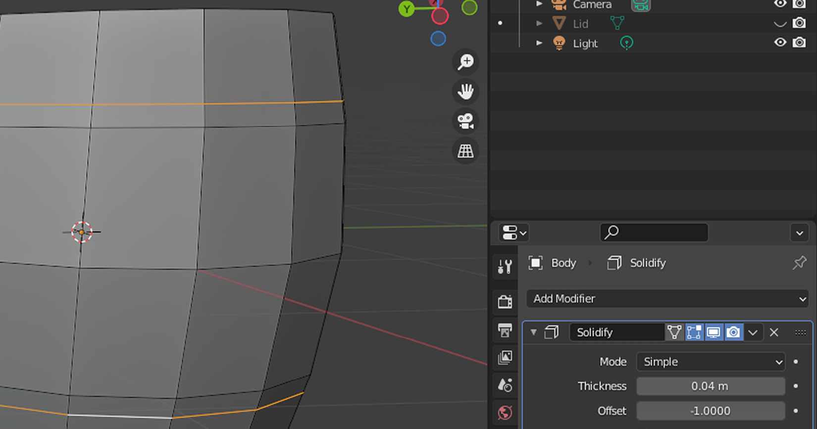
Figure 1.12 – Two separate cuts from both ends approaching the middle section
You’ve already seen how to select an edge loop: it involved holding the Alt key and clicking an edge. You’ll do something very similar except it’ll be for selecting a face loop. For this, make sure the face icon is clicked in Edit Mode. Alternatively, while in Edit Mode, you can press 3.
When you hold the Alt key and click an edge, you’ll be selecting the faces that are adjacent to that edge you’ve just clicked. It’ll also keep selecting the other faces that are in a similar direction to complete a loop. Try it a few times with horizontal and vertical edges to see how the loops’ direction changes accordingly.
What you must do is select all the faces that make up the two rings that are close to the top and bottom of the barrel. The following screenshot shows which faces should be selected so that you can separate them to form the metal rings:
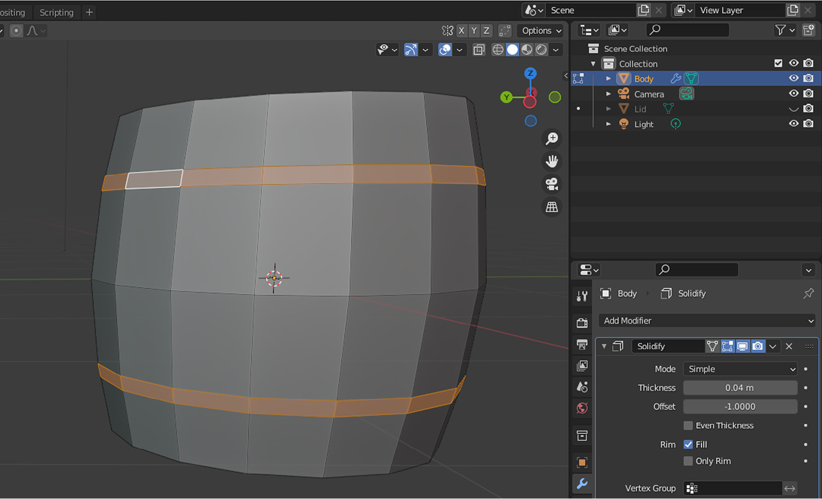
Figure 1.13 – You’ve got to have something selected so that you can separate it
Once you select the first loop, you can hold down Shift and repeat the previous operation to keep adding more loops to your selection.
Now, you are ready to separate those faces. Hit P to bring up the Separate options and choose Selection. Now, you can rename the newly created Ring object. If you go back to Object Mode, you’ll see that you can select each object individually. Select the ring; you’ll see that the Solidify modifier still exists for this new object too. Isn’t that handy?
The thickness value in the modifier is the same, but what would happen if we changed the sign of that value? If you click the Thickness field, it will let you type in a value. Adjust it so it shows -0.04 m. As you can see, it’s still the same thickness, but in the other direction – it looks like we have those metal rings around the body of our barrel finally!
Now, let’s learn how to add another ring for the middle section. You can follow similar steps to create two more loops, one above and one below the center loop. However, you can do better.
Select the middle edges by conducting an edge loop operation and then triggering the Offset Edge Slide option under the Edge menu or pressing Shift + Ctrl + R. This is very similar to Loop Cut and Slide but it has two major differences. First, this operation will consider an edge as its baseline and move the new edges off in opposite directions. Second, you need to click just once when you are happy with where the new edges will sit. Choosing 0.1 for the Factor value in the operation’s properties might be a good number if you’re having sensitivity issues with your mouse.
We’ll follow a similar procedure: select and separate. In face edit mode, you will use a combination of Alt + Shift by clicking one of the vertical edges sandwiched between your new loops. After you separate the middle faces, you’ll be left with an important decision: should you rename your new object and invert the direction of thickness in its modifier just like you did for the upper and lower rings? In essence, you want your new object to join its fellows. That’s exactly what you’ll do next but with a clever trick without repeating yourself.
Which mode?
During the modeling process, there are times when you’ll need to edit parts of your model. In this case, being in Edit Mode will be necessary. However, when you separate chunks from your models, you’ll most likely want to go back to Object Mode to do something with this new object. So, going back and forth between these two modes will be necessary and feel natural after a while.
In Object Mode, first, you must select the middle ring you have just created. You don’t need to rename it; you’ll see why shortly. You must add one more object to your selection by holding Shift and clicking the ring in 3D Viewport. Make sure your last click is on the ring object you created a while ago. The order of clicks matters at this point. The last object you interact with will be considered as the active object by Blender. It will be marked with a yellow outline compared to orange outlined objects, which are part of the selection but not considered active objects.
Once you have your rings selected in the correct order, you must join them by pressing Ctrl + J. Did you notice what just happened? Let’s break it down:
- You can no longer see Body.001 in the Outliner
- The Ring object has accepted Body.001 into the fellowship
- The Ring object’s Solidify modifier has been applied to Body.001
There are no longer separate pieces since all those separate parts are now considered as one object, as shown in the following screenshot:
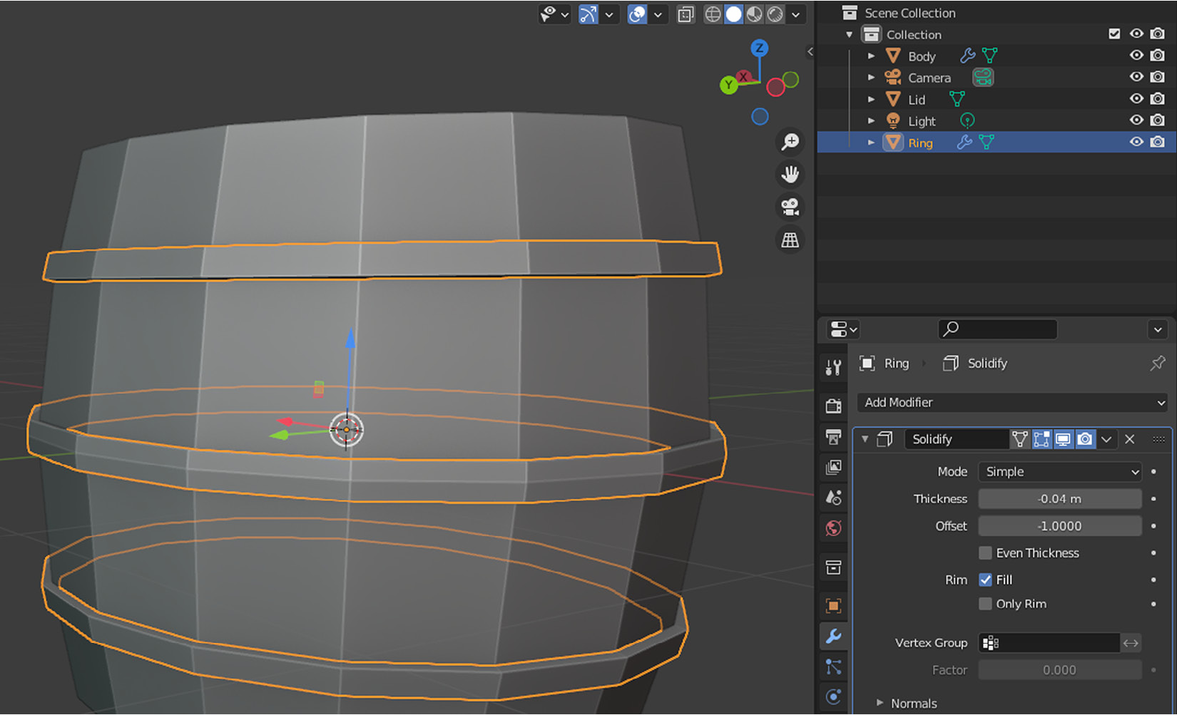
Figure 1.14 – One ring to join them all
As you get more confident in Blender, you’ll find that you can follow different methods to achieve the same result. There is no right or wrong way, but rather time-saving habits, and you’ll develop your own since every designer has their preferred way of doing things. Sometimes, there are other concerns, technical or artistic, that will limit your workflow. However, as a beginner, you should observe how other artists are creating similar objects. Luckily, there are plenty of examples out there, so learn, experiment, and divert as you go.
Earlier, you had to separate the lid. After that, you made changes to the body and even added rings. Now, it’s time to put a lid on your barrel.
Finalizing the lid
If you hid the lid once you separated it, you can click the eye icon in Outliner to turn it on. You need to do a basic scale operation to put the lid in its place. To achieve this, first, select the lid, and then do the following:
- Press S.
- Type in 0.96.
- Press Enter.
Why such a precise value? Because we’ve been using 0.04 m in the Solidify modifier. So, we should reduce the scale of the lid by 4%. This will save us from the trouble of lining up all the edges of the lid so that they are flush with the inner side of the barrel. If you have been using a different value in your modifier, you’ve got to compensate your scale value in this step so that both add up to 1 in the end.
You’ve done it! With the lid in the right place and looking just below the rim level, the barrel is complete. Check out the following screenshot and compare it to your creation:
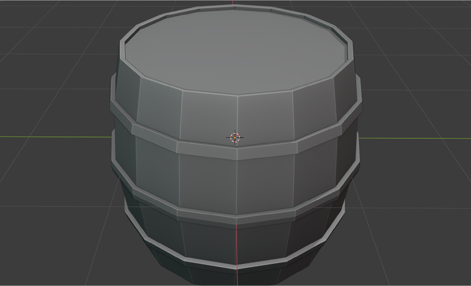
Figure 1.15 – A wooden – rather gray – barrel in its glory
If you decide to create this barrel from scratch again, perhaps you can place the upper ring close to the lid, and the lower ring at the bottom. Placing five rings is also a possibility, but you may want to adjust the height of each ring in case the composition looks busy.
So far, you have used one modifier, and it has served you well. Let’s dive into more modifiers and see how powerful they can be.
Automating with modifiers
A modifier is a non-destructive way of applying an operation to change an object’s geometry. This is often preferred when you don’t want to take repetitive steps or the operation is complex enough that you don’t want to directly alter the object’s geometry.
When you applied the Solidify modifier, you must have seen that there are so many other modifiers. Could you imagine what you can do with each one? How about you use a few modifiers in a row? Yes, you read that right. You can stack up many modifiers and create complex shapes with little effort.
However, there is an important detail you must pay attention to – their order matters! New modifiers are always added at the bottom, and they work in conjunction with the previous modifiers in the stack. Thus, the effect is compounding. If you logically stack your modifiers, you could create something as complex as what’s shown in the following screenshot with only a few primitive objects in no time:
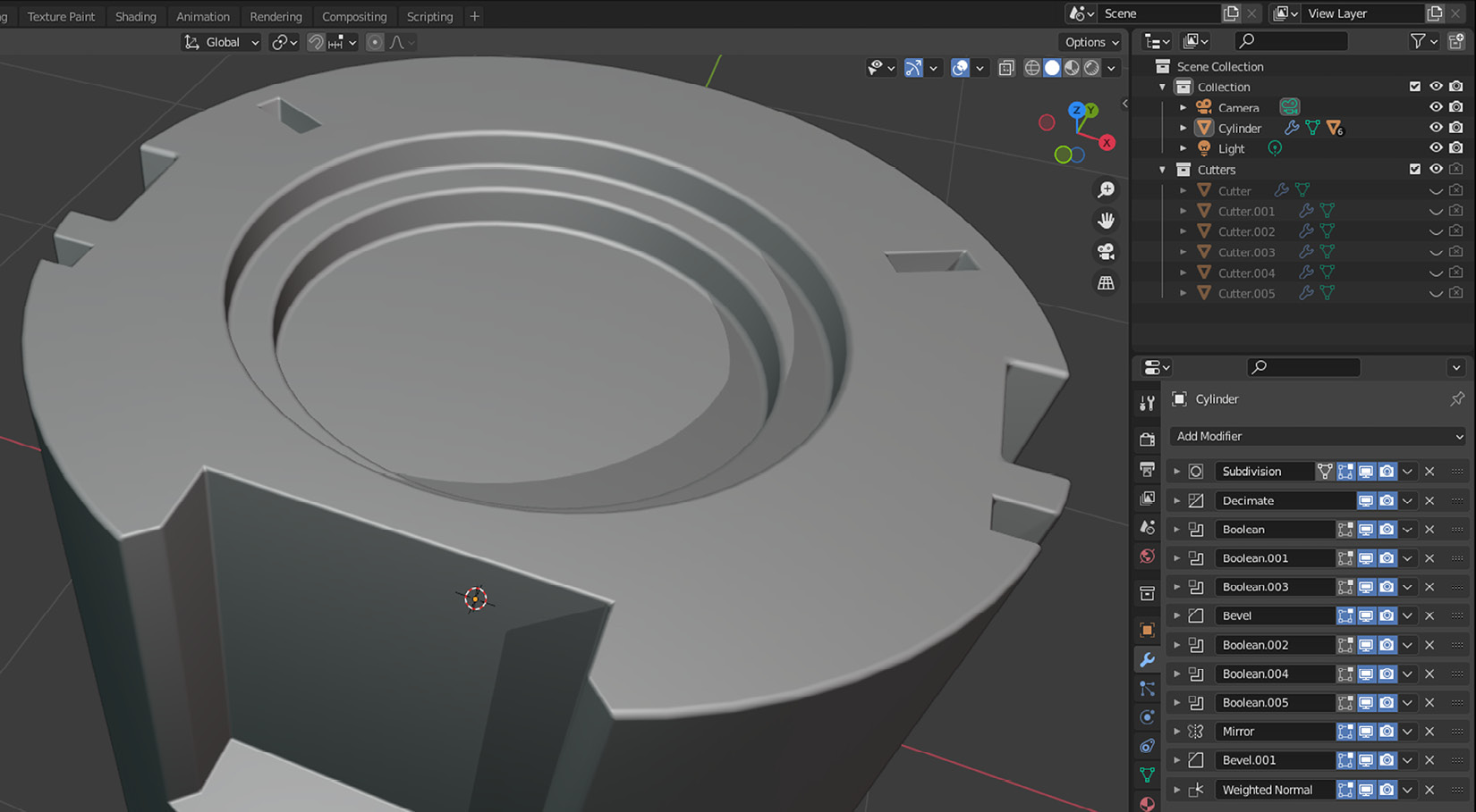
Figure 1.16 – Modifiers help you create something this complex easily
This object is using primitives such as cylinders and cubes, but the result looks interesting. This is thanks to a hefty list of modifiers and the order that they’ve been used. Some of the modifiers have been applied multiple times with different values, but here is a list:
- Subdivision
- Decimate
- Boolean
- Bevel
- Mirror
- Weighted Normal
At the time of writing, Blender has over 50 modifiers. Describing each would fill a book. Most likely, you’ll stick with the modifiers that are in the Generate category. Here is a set of modifiers you’ll use most of the time:
- Boolean: This is one of those modifiers that is used a lot and it comes in three sub-modes:
- Difference: Subtracts the value of one object from another
- Union: Will combine both objects
- Intersect: Will only keep what’s common in both meshes
- Bevel: Sometimes, you want to have more detail, especially along sharp edges so that they don’t look too harsh – the more surface there is for the light sources to reflect on, the more realistic it’ll look to the eye. This modifier will also work on vertices if you want to soften those sharp corners.
- Array: This makes copies of the object it’s assigned to in different axes, with or without some offset if you wish. You could have a fixed number of copies or fill a particular length with as many copies as you can fit in that distance.
- Mirror: This is like the Array modifier except it creates one copy along the axis you select. You can pick multiple axes. Thus, it’s possible to start with only a quarter of the object and mirror it on the X and Y axis so that you have one whole object. This allows you to keep your changes to a minimum in the original quarter so that you can mirror your changes to the rest of the mesh.
When you add your modifiers, it’s sometimes not obvious which order you should stack them in. Luckily, it’s possible to change their order or temporarily disable them by using the buttons that are part of the modifier’s header.
While creating rings for the barrel, you could have used a different technique to achieve the same result: extrusion. This would require you to select what needs to be extruded – in this case, all the faces that make up the ring – and extrude along each face’s outward-facing direction. Extrusion, in essence, is a technical term for moving vertices, faces, or edges.
Modifiers have a big advantage compared to classic methods such as pushing and pulling vertices and faces around. Wouldn’t it be convenient to come back later and fine-tune your changes further? If you happen to select the lid now and come back to the Body object, the modifier will still be there. You won’t have this kind of flexibility with permanent mesh modifying techniques such as extrusion.
Summary
In this chapter, you learned about the benefits of low-poly modeling. Then, you created a wooden barrel from a primitive cylinder and incorporated modifiers. Although textures may give a more realistic look to your models, you also know you can do without them.
As an exercise, feel free to create a potion bottle. You can start with a cylinder, just like you did for the barrel. The loop cuts and the scaling down values will be different to give it a conical shape. This is your chance to practice modifiers. A finished potion bottle is waiting for you in this book’s GitHub repository if you want to see a finished example and compare yours.
Several shortcuts are commonly used by many professionals during the modeling process. Here is a list you’ve used so far:
- Shift + A: Add an object
- Tab: Switch between Edit Mode and Object Mode
- Ctrl + R: Introduce loop cuts
- Ctrl + J: Join
- S: Scale
- P: Separate
In the next chapter, you’ll learn how to apply materials to your models so that parts of your model can still have a different look and feel without textures.
Further reading
The section’s title suggests reading sources, but sometimes seeing is even better. Just as a picture is worth a thousand words, a video might be worth a thousand pictures. So, here is a list of URLs for video content that might be useful for all levels of Blender practitioners: