4
Adjusting Cameras and Lights
When you start a new scene, there are default camera and light objects in the Outliner. Although they are part of the scene, when you are modeling a new object, rotating around it, and looking at a material preview of it, you are still using Blender’s internal camera and lighting system. This default behavior is good for working fast but doesn’t produce artistic and accurate results.
In this chapter, you’ll learn what a camera does and how to employ lights to get the look you want. The premise is simple: you can’t see anything without a light, and you can’t record or capture anything if you have no apparatus to do so.
Although it sounds like we are covering two distinct topics, we’ll talk about both cameras and lights in this chapter. Between the two, we’ll prioritize lights over cameras; you’ll be provided with an explanation of why.
Thus, just like in real life, a camera and light conditions work together, and they go a long way to get the best shot you want. To that end, we will cover the following topics:
- Rendering a scene
- Understanding light types
- Introducing MatCap and Ambient Occlusion
After reading this chapter, you’ll know how to pick the correct light type and capture a shot of your scene. You’ll also know why you may want to postpone setting up cameras and lights. However, we’ll offer you a way to attain some semblance of visual fidelity.
Technical requirements
We’ll be entering new territory in this chapter, so it will be safer for you to rely on the files in this book’s GitHub repository: https://github.com/PacktPublishing/Game-Development-with-Blender-and-Godot.
The appropriate filename will be mentioned when it’s relevant. These files have already been set up for you so that you can focus on the material in this chapter.
Rendering a scene
In the computing world, the word render is similar to its other meanings in a dictionary. The rendering process in Blender will take a raw scene and produce a refined result. In more advanced cases, where your scene may have a physics or a particle object, this process will be responsible for calculating the state of these dynamic objects too. However, for brevity, we’ll only look at what role the camera and light objects play in renders.
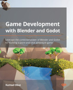
Let’s create our first render by doing the following:
- Start a new Blender scene.
- Press F12.
Alternatively, you can use the Render menu near the application’s title at the top. This should give you the following output:
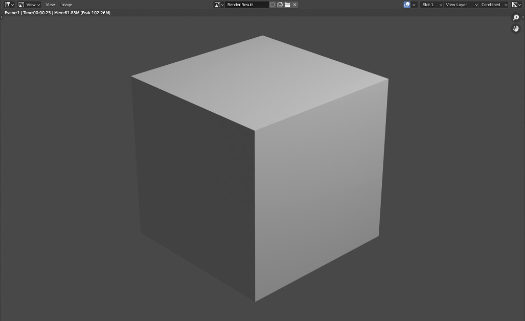
Figure 4.1 – Your first render of a default cube with Blender’s default camera and light options
This is nothing exciting perhaps since this is pretty much the look you are used to seeing while working within Blender. The render is displayed in a separate window that covers the Blender window you were just working on. Therefore, you can close this window by pressing the operating system’s close button or by pressing Esc to return to Blender.
If you take more renders and go back and forth, you’ll notice that the grid underneath the cube and other objects, such as the camera and light, are no longer part of the render. This is expected. These objects, called gizmos, will facilitate things for you but won’t be with you at the end of the journey. They work like scaffolding during the construction of a building. Although they are helpful while doing the work, they are taken away after the job is finished.
Let’s repeat the previous exercise by changing one thing. What would happen if there were no cameras in the scene? Time to experiment:
- Right-click Camera in the Outliner.
- Delete this Camera object.
- Press F12.
Did you expect to see a pitch-black render? Instead, you got an error stating that no camera was found in the scene. No camera means there isn’t any instrument to render your scene, so Blender displays an error message.
Let’s run a similar experiment by removing the Light object. After starting a new Blender scene, follow these steps:
- Right-click Light in the Outliner.
- Delete this Light object.
- Press F12.
Let’s speculate about what we expect to see. We have a camera to render the scene but no lights. Even though the cube object is part of the scene, we should not be able to see it. And yet, if you look at the following render, you will see a silhouette of the cube:
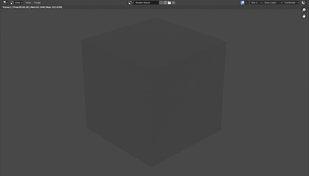
Figure 4.2 – An unexpected render when there are no lights in the scene
Most software applications come with default settings for the sake of helping out the user. In this case, Blender comes with a background color that contributes, unfortunately, to the result in the previous render. If you were to change the color of this setting to black, for example, then you’d have a completely black render. To achieve that, follow these steps:
- Switch to the Shading workspace, as you did in Chapter 3, Adding and Creating Textures.
- Switch from Object to World mode in the Shader Editor by using the dropdown near where the four views meet.
- Change the Background node’s Color property so that its Hex value is 000000.
The following screenshot shows the setup for changing the background color:
Figure 4.3 – We can also use the Shader Editor to change the scene’s background color
If you take another render now, you’ll notice that it’s all black. There is neither direct nor indirect light or color contributing to the result. So, although things are looking rather dark, this is the result we expect to see. When would this be useful? If you would like zero surprises, which means you’d rather control every single light source and how much they contribute, then picking a black color for the background might be a good idea.
However, most Blender users are artists, not scientists. So, they often have multiple light sources and adjust these objects’ settings to achieve visual fidelity, not scientific accuracy. Therefore, leaving the background color alone might be something you’ll do as well.
Speaking of light sources and their settings, this is the right moment to segue into learning about the different types of light Blender employs. We’ll light things up in the next section.
Understanding light types
So far, we have seen a render where the light object plays a role and another render when the light object was missing. We haven’t discovered what this light object is. In this section, we’ll get to know different types of lights. By the end of this section, you’ll have a good level of knowledge of each type and why they matter.
We’ll do this discovery in the context of the Eevee render engine because it simulates what game engines will do with your scene well. Since it’s enabled by default, you don’t need to make any changes at this point. Hence, you first need good knowledge of lighting your scene with the basic types of light. That’s what we are going to do next.
Types of light
Let’s look at the different types of light that are available:
- Point: This is the default light type you get when you start a new Blender scene. It’s also called an omni light sometimes, short for omnidirectional, since it casts light in all directions. Lightbulbs are a decent real-life example of this light. Of course, in reality, lightbulbs don’t cast light through their base but it’s a good approximation.
- Sun: This type is used when you need a constant intensity of light. In other words, the light is so powerful that it doesn’t lose any of its intensity along the way. Unlike the other light types, Sun, just like the Sun, also sends light rays in one direction only. Thus, the light rays are coming from an infinitely far away distance without losing their potency.
- Spot: When you need a flashlight-like light source, this is the light type you should use. It will emit a cone-shaped beam of light in the direction you point it. Most shopping centers and stores have lights of this type, usually hidden in the ceiling.
- Area: If you want to have a light source that has a large surface such as a window, TV screen, or office lights such as conventional fluorescent tubes, then Area lights are the way to go. You can also define the shape of the area. Since it is a considerably larger source of light in contrast to Point lights, the result, including the shadows, feels softer.
To get a much better feeling about what each light type does, you will open a file that’s prepared for you so that you can quickly switch between different types of light. Follow these steps:
- Open the Start folder inside the Chapter 4 folder. This can be found in this book’s GitHub repository, which was mentioned in the Technical requirements section.
- Open the Lights.blend file.
- Hold Z and then press 8 to switch the visuals to Rendered mode.
The scene contains a cube and a large plane as a base to hold this cube. The four different basic light types are all in the same position, all with their default settings. Only the Spot light is enabled in the Outliner and you can see its effect in the following screenshot. By clicking the eye icon next to each light type in the Outliner back and forth accordingly, you can see what each light does. Notice the overall feeling each light creates by illuminating a certain spot or changing how the shadows appear:
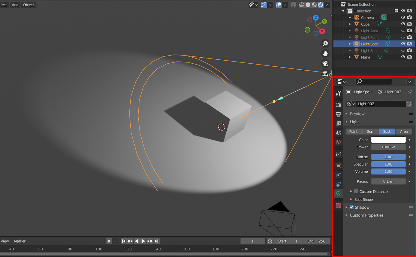
Figure 4.4 – A light object’s, specifically Spot light’s properties
Now that we have seen what each light does, let’s learn about some of their properties.
Basic properties of light
The sample file was set up so that when you open it, the Properties panel should already be switched to the appropriate Light tab; this will display the five common properties that all the basic lights share:
- Color: This is the tint of the emitted light. If you are designing a fireplace, you may want to pick an orange or red tint, for example.
- Power/Strength: This defines how powerful your light source is in Watts. Thus, the higher the value is, the more powerful the light will be. In the Sun light’s case, the Power property is labeled as Strength, but the concept is still the same. If you are designing a scene where accuracy is paramount, and you would like your lights to be as realistic as possible, then you are in luck. The Power of Lights section at the following URL lists values for some known light sources: https://docs.blender.org/manual/en/2.93/render/lights/light_object.html.
- Diffuse: In Chapter 2, Building Materials and Shaders, you worked with materials and set the color for the materials you applied to the barrel parts. The Diffuse property of lights works like a multiplier. So, keeping it as 1.0, which is the default value, won’t change the perceived color of a material. Decreasing it will diminish the color’s effect on a material. In essence, this value determines the impact a light source has on a material’s color.
- Specular: This is similar to the Diffuse property, except it affects the Specular quality.
- Volume: This is a bit of an advanced topic that involves more sophisticated settings when you set up materials. We won’t cover advanced material settings in this book. However, like the Diffuse and Specular properties of lights, which work as multipliers, this property determines the light’s contribution over a volume.
Out of these five properties, you’ll most likely never touch Diffuse, Specular, and Volume. This is because, most of the time, it makes sense to change diffuse and specular values in a material. Also, volumetric light is an advanced case that can be handled via other means, similar to adjusting it via a material’s properties.
More esoteric lights
If you are the curious type and read up on lighting, generally within the context of 3D applications, you will hear of terms such as ambient light, global illumination, and others. Even though those terms are relevant and important when producing a render, we won’t cover them in this book for two reasons. First, basic light types are often enough because this will give you a more direct result and feeling for your scene. Second, the advanced lighting systems rely on and affect basic lights by making tweaks. So, understanding the basic types would be a better investment as a beginner.
Specific properties of each light type
Although you now have basic knowledge of what each light does, we haven’t investigated what kind of setting contributes to the uniqueness of these lights. Now, let’s look at each light’s settings, which give the light its characteristic look and feel.
Point
Radius is a setting that’s also used for Spot lights, but we’ll cover it under this section since there is nothing else going on with Point lights. We’ve already considered a lightbulb as an analogy to Point lights. In reality, lightbulbs come in different sizes. So, you can imagine the radius value, measured in meters, as a mechanism to determine how big the lightbulb is.
The effect this value has is in the way the shadows are calculated. The default value, 0.1, will produce a rather sharp shadow. Try to increase this value to 1.0. You’ll notice that there will be multiple shadows overlapping each other, following a direction away from the light source.
If you increase the radius to 10.0, something interesting will happen. The bulb is large enough that it will encompass the cube. It’s so large that it intersects with the plane too. The shadows for the cube are no longer following a direction strictly away from the light source. The light source is so large it’s as if there are multiple tiny point lights scattered inside a sphere with that radius value.
Sun
In some 3D modeling software and game engines, the Sun light is often labeled as directional light. There is a good reason for that. In real life, the Sun is so far away but so powerful that it’s as if all light rays are parallel to each other. So, the Angle property defines the direction of the rays.
What about the position of a Sun light? You could try to move its location, but the overall effect on the scene won’t change because the light rays are assumed to have constant energy, regardless of where they are coming from. So, the angle is the only meaningful factor for this light type.
Spot
A Spot light has the same Radius property as a Point light does. So, initially, they start as the same thing, then a Spot light sheds its light while following a conic shape.
There is a collapsed section labeled as Spot Shape in the Properties panel for this light type. This section houses two properties:
- Size: Measured in degrees, this value is the angle of the cone’s origin. The higher the value is, the wider or larger the area will be once the light hits a surface. Similarly, lower values will focus the light on a smaller area.
- Blend: Once you have defined the area of light via the Size property, you’ll have shaded areas outside the illuminated zone. The Blend value, which will be between 0.0 and 1.0, works like a percentage to adjust how smoothly these two contrasting zones blend into each other. Lower values will have a sharper transition. So, having it as 0 means a very sharp separation.
Area
For this light type to be more effective, deciding on its Shape setting is important. Four shapes exist:
- Rectangle
- Square
- Disc
- Ellipse
For all of these, you can customize the size of the shape. For example, the Rectangle shape will accept two values, but the Square shape will only need one dimension. You won’t see much difference in the test scene if you play with different values. However, rest assured that they make a real difference in a much more complex scene where you distribute Area lights with different shapes.
Wrapping up
Adjusting light settings is only the beginning. Most 3D professionals dedicate themselves to certain disciplines. Lighting is one of these disciplines where you work on topics such as global illumination, bloom, volumetric effects, and many other advanced topics we won’t be covering in this book. With that being said, using cameras and lights in Blender may still be useful to get a basic feeling about the artistic direction you are taking. For example, if you are designing a car, the headlights will most likely house a Spot light. If the model were a torch, a Point light might be appropriate.
Now, you may be thinking that we didn’t cover a lot about lighting, but we also covered even less about the camera. This is because this book is about game development. In Part 3, Clara’s Fortune – An Adventure Game, we mentioned that most of our work will be done in Godot, so you’ll see that there will be many things we’ll set up and fine-tune in Godot. Some of that effort will be for the camera and different light objects. Since we’ve been building individual models or constructing materials for our models, which will all be imported into the game engine in the end, there is no need to do a meticulous amount of work within Blender regarding cameras and lights. In other words, it’s practical to set up cameras and lights in Godot because the settings in Blender won’t transfer.
Now that you know why you should generally ignore Blender’s cameras and lights, let’s look at two helpful methods that will make your time more pleasant while still working in Blender.
Introducing MatCap and Ambient Occlusion
Since making more investment in a high-fidelity lighting setup in Blender no longer makes sense, we should perhaps investigate different ways to make our scenes look better. What we’ll do next still means what you see won’t be exported. However, it means you can look at models that no longer have the default and boring gray look. Why not? Working with things that look nice sometimes feels nicer and increases productivity. We’ll look at two techniques that will help you distinguish your models’ details.
MatCap
MatCap stands for material capture. We won’t get into the technicalities of how a MatCap is constructed but, suffice it to say, it’s a type of shader Blender uses internally to give a different look to the models. Normally, you’d need to switch to Material Preview mode to see how your materials would look on your models.
However, during the modeling process, you usually work in Solid mode because it’s more performant for Blender to show you the changes you are making to your models. Thus, while still working in Solid mode, if you want to have a better visual as if you are in Material Preview, you can instruct Viewport Shading to use MatCap. So, it’s the best of both worlds.
To make sure you are using Solid mode, do the following:
- Press Z.
- Then press 6.
This will switch Viewport Shading to Solid mode. It’s also represented as a disc in the second icon at the top-right corner of the 3D Viewport. We’ll make some changes to Viewport Shading so that your models can have more pronounced details. If you click the down-looking arrow on the right-hand side of those icons, you’ll expand a panel. This panel is shown in the following screenshot:

Figure 4.5 – The default Viewport Shading options
The settings in that panel let you change the way the models are displayed while you are editing them. You can already see a preview of the current settings as a sphere in the upper section. Let’s click the second button, MatCap, under the Lighting title. This should already change the look of the preview in that panel, as well as the model’s look in the scene.
We won’t be discovering the Color part but try out the Random option for the barrel from Chapter 1, Creating Low-Poly Models. You’ll see that different parts of the barrel take random colors. This helps to distinguish separate parts in your scene. Similarly, we will leave the Background setting set to Theme.
Let’s investigate the Options section and focus on the parts that will give us a decent result:
- Enable the Shadow option.
- Set its value to 0.5.
You won’t normally see the effects of the light sources in Solid mode, but the last operation will create a shadow effect. It’s a cheap effect that efficiently creates depth.
Sometimes, your models will have parts that are away from the center of mass. These outer parts may also create areas that would look deeper from your point of view. Hence, you’ll have cavities. To mark these areas more clearly, do the following:
- Enable Cavity.
- Set its Type value to Both.
- Set World Space like so:
- Ridge to 0.5
- Valley to 1.0
- Set Screen Space like so:
- Ridge to 0.75
- Valley to 1.0
This should create a big change in the way your models look. The Cavity option, with Type set to Both, will seek parts of your models that are at different elevation levels and accentuate them. In a way, if your model was laid out like a landscape, the ridges and valleys would be emphasized so that they would be more noticeable. The values we picked are a bit arbitrary, so feel free to alter them according to your taste or the complexity of the models.
Last but not least, in the settings for MatCap, if you wish, you can pick a different material. After all, we are still looking at a gray cube, even though we have improved its perception. For example, you can do the following:
- Click the sphere preview under the MatCap button in Viewport Shading.
- Select the third sphere in the second row.
If your version of Blender has the selection interface organized differently, we are looking for a sphere that looks like brown clay. This will change the look of your cube to, well, muddy clay. The following screenshot shows what we have done so far:
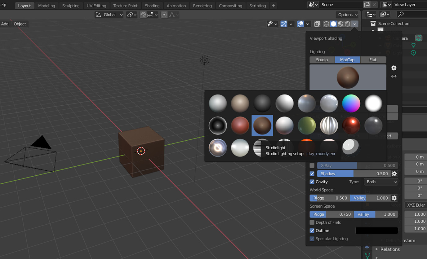
Figure 4.6 – Viewport Shading offers many ways to create a different look for your models
If the muddy color is too dark, then the second sphere in the first row is a nice alternative. However, keep in mind that this is only for you to feel at ease while working with your models in Solid mode. None of these changes will have any impact on the result when you render or export your models to other software. These are, in a sense, throw-away materials that will make your experience in Blender more pleasant.
So far, we have treated the Solid view as if it was Material Preview. This is useful when you want a bit more visual clarity without previewing the model’s assigned materials since that makes extra calculations by taking into account the lights too. Next, we’ll look into a way of doing something similar in Rendered mode.
Ambient Occlusion
In this section, we’ll discover another handy visual tool that can help you have a bit more visual fidelity. This tool is called Ambient Occlusion (AO), and it’s also a method that’s used in most games to create a more realistic look. Let’s explore how and why this works.
Let’s get the definition out of the way first. We have two names: ambient and occlusion. In the context of Blender, as you may have guessed, ambient is a term that’s used to describe the overall light conditions. We switched the background color to black to modify the ambient light near the end of this chapter’s Rendering a scene section. So, we are already familiar with this concept.
Occlusion means to obstruct or block something. In our context, it means to obstruct light. So, we want some light to be obstructed or occluded. But where exactly would we want this?
Take a look around wherever you are. You’ll notice that some areas, by having a flatter surface, will be exposed to the natural or artificial lights coming off the ceiling or windows. Light – more specifically, the photons that make up the light – will be bouncing off these surfaces. Wherever these flat surfaces meet and make some sharper and some more moderate angles, they will be forcing the photons to scatter in a zigzag manner. As a result, it’ll be harder for light to reach certain spots, so the geometry of your models is going to occlude some of the light.
To see the effect of AO, open any of the following files from this chapter’s Start folder:
- Lights.Area.AO.blend
- Lights.Point.AO.blend
- Lights.Spot.AO.blend
- Lights.Sun.AO.blend
Also, remember to switch to Rendered mode by pressing Z followed by 8. Otherwise, the effect won’t be visible. Do you notice the darker part where the cube meets the plane? That’s AO, as shown here:
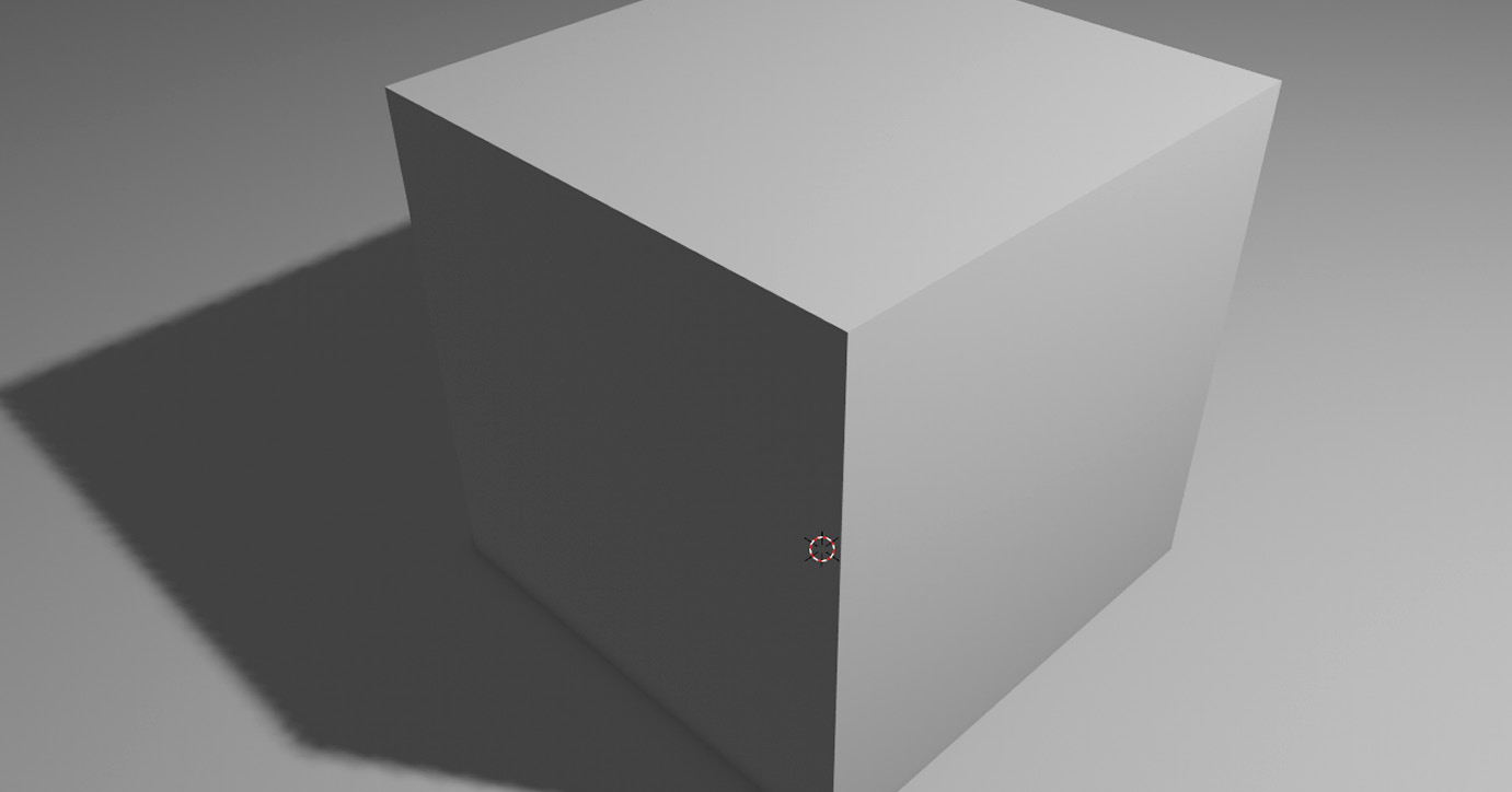
Figure 4.7 – Ambient Occlusion visible where the cube touches the plane
The example files have been prepared so that the Ambient Occlusion option should already be visible on the right-hand side in the Properties panel. By switching it on and off, you can observe the behavior. AO affects the edges as if there is an extra volume of shadow, where shadows naturally would occur. This makes it look more realistic. We’ll look at how to take advantage of AO as a separate effort inside Godot Engine later in this book.
Additionally, in the AO settings, if you pick a higher Distance value, it will sample a larger area from the object’s contact zone. This may help you have smoother or sharper AO.
We’ve covered a great variety of topics in this chapter. Now, it’s time to summarize what we’ve learned.
Summary
We started this chapter by rendering a scene with and without a camera and lights. During this effort, we utilized Shader Editor, which was introduced in the previous chapter to change the background color, also known as ambient color.
Then, we looked at different light types and how each type can be used to simulate real-life cases. We did this using the Eevee rendering engine. Should you switch to the Cycles render engine, the lights will have additional and more advanced properties, but the concepts you learned about in this chapter will hold.
We also discussed the fact that your rendering concerns will be left for later when we tackle things in Godot. However, it’d be a much more pleasant experience if we could work with better-looking things. To that end, you were introduced to two different methods.
The first method is MatCap, which you can use to change the way models look, despite not turning on material previewing. The second method, Ambient Occlusion, involves getting a feeling of where objects meet and how they behave under existing light conditions. You can use both methods at the same time if you wish.
In the next chapter, we’ll move things a bit. You’ll be studying and preparing a model for animation. For this effort, you’ll utilize a process called rigging and simulate a skeleton-like structure inside your model so that you can animate it.
Further reading
Although this chapter covered cameras and lights, such topics are usually covered under the Rendering title in many publications. That’s because there are different rendering engines, and each one treats lights and cameras differently. Also, post-processing and color management might be your concern if you want to take on more advanced renders. So, cameras and lights are only a small portion of the rendering process. To learn more, Blender’s official documentation page might be a good start: https://docs.blender.org/manual/en/2.93/render/index.html.
Also, here are a few online resources that might help you dive deeper: