12
Interacting with the World through Camera and Character Controllers
You have been preparing little bits and pieces for the game world, especially in the last two chapters. In Chapter 10, Making Things Look Better with Lights and Shadows, you added Light objects to sconces and candles. You even placed a script to adjust these objects’ lit state. Then, in Chapter 11, Creating the User Interface, you built a new scene by introducing Control nodes. This effort was for simulating a note from Clara’s uncle, Bert.
Although we’ve been taking steps to make things more sophisticated, pretty much everything feels static. In this chapter, we’ll show you a collection of practices that will build a connection between game objects and the player. This will make the project look live and feel more like a game.
The first thing we’ll look at is the Camera node and its settings. Godot’s viewport has been letting you see different scenes via a temporary construct so that you could work with the software. Such a transitory concept won’t be enough, so we’ll work with our camera system.
Next, we’ll focus on building a connection between some of the game objects in the world and the player. This involves detecting mouse events on a 2D surface and projecting these events into a 3D space. There might be different interactions such as hovering, clicking, pressing, and likewise, so we’ll look into ways to detect the action we want. For example, we will click a parchment left on the pier to bring up the note we worked on in the previous chapter.
Similarly, if the click happens to be on one of the areas where we would want to move Clara, we need a system that can do the pathfinding for us. To that end, we’ll investigate new Godot nodes, Navigation and NavigationMeshInstance.
Lastly, why not add a bit of animation? After we discover how to move a game object between two points in the world, we could instruct this object to trigger the appropriate animation cycle. In our case, Clara will switch between her idle state to her walking state. As a result, we’ll revisit some of the notions we got to know in the Importing animations section of Chapter 7, Importing Blender Assets into Godot.
As you can see, we are going to utilize a lot of the topics we have already visited, yet there is still a lot of new stuff to discover and learn. If we could enumerate it, it would look like this:
- Understanding the camera system
- Detecting user input
- Moving the player around
- Triggering animations
By the end of this chapter, you’ll have a much better understanding of camera settings in general, and you’ll be able to detect your player’s intentions and relate them to actions in the game. Thanks to an easy method of pathfinding, you’ll move Clara around the level to a location you want, and—finally—trigger the appropriate action to simulate her walking.
Technical requirements
We’ll continue where we left off in the previous chapter. This means you can keep working on your existing copy. Alternatively, you can start with the Finish folder of Chapter 12 in this book’s GitHub repo: https://github.com/PacktPublishing/Game-Development-with-Blender-and-Godot.
We have several new assets that are necessary to do the work in this chapter. These assets are in the Resources folder next to the Finish folder. As usual, merge these with your project files.
Understanding the camera system
In Chapter 4, Adjusting Cameras and Lights, we briefly touched on the concept of a camera in Blender. We learned that we couldn’t render a scene without one. Although we took a render in the end by introducing a camera, we never talked about the different settings a camera can have. That was done intentionally because the know-how we would attain in Blender would not directly transfer to Godot. Fortunately, now is the right time to study in detail what a camera can do for enhancing the gameplay experience.
Not only are we going to get to know how to set up a camera that suits our game, but we are also going to discover different types of cameras Godot has in its inventory. As usual, or as it is something you might hear as a joke on internet forums and memes, there must be a node for this type of thing in Godot.
Yes, there is. In fact, there are four camera nodes, as outlined here:
- Camera: This is the core class that serves as the base for all the other camera types. Even though you can have multiple Camera nodes in your scene, there can only be one active camera. And, similar to Blender, no camera means nothing to see here.
- InterpolatedCamera: This is an enhanced version of the Camera node. It comes with three extra properties that turn a regular Camera node into a mechanism that tracks and follows a target. It’s quite handy if you are developing a game with an over-the-shoulder camera look. If the game character is the target, when the target moves, the camera will catch up.
Unfortunately, this node will be removed in Godot 4. Luckily, it’s not difficult to recreate its functionality by attaching a short script to a Camera node. In other words, if you remove the fancy bits of an InterpolatedCamera node, you get the Camera node, hence the decision to drop it in future versions.
- ClippedCamera: This is another type of special Camera node, and fortunately, it will be kept in Godot 4 since it’s an advanced camera system. Our game is currently not using PhysicsBody nodes that are responsible for determining which objects can pass through each other or bump and bounce back when the bodies in motion connect with a colliding surface. For that reason, we won’t investigate this type of camera, but you might want to check this one out if you don’t want your cameras to travel through walls. It will behave like an object respecting physics rules.
- ARVRCamera: You might have guessed it: this is used for virtual reality (VR) projects. It isn’t something you’d utilize as a standalone node since it depends on a lot of other nodes that have augmented reality/virtual reality (ARVR) at the beginning of their names. Building a VR project is an advanced topic that deserves probably a whole book dedicated to the subject. For that reason, we’ll skip this node too.
Besides the camera nodes for 3D workflows, there is also the Camera2D node that is used in 2D projects. Thus, there are five types of cameras in total.
Out of all these types we presented, the most promising candidate is the InterpolatedCamera node. Why? Because an InterpolatedCamera node is essentially a Camera node with extra pizazz such as target and track functionality. So, in your Godot 3 projects, you can start with InterpolatedCamera and treat it like a Camera node until you need that extra functionality.
Since we are continuing our work from the previous chapter, it makes sense to tidy up some loose ends. Let’s start with that first, then we can move on to introducing camera settings.
Tidying things up for interactivity
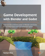
The last thing we did in the UI.tscn scene was skinning UI components. During that effort, we had already turned off the visibility of the Panel node that was responsible for displaying the note from Clara’s uncle. Then, we introduced a series of UI nodes, all grouped under an HBoxContainer node. We’ll turn that container off too, but let’s run the project first by pressing F5. You might see something like this:
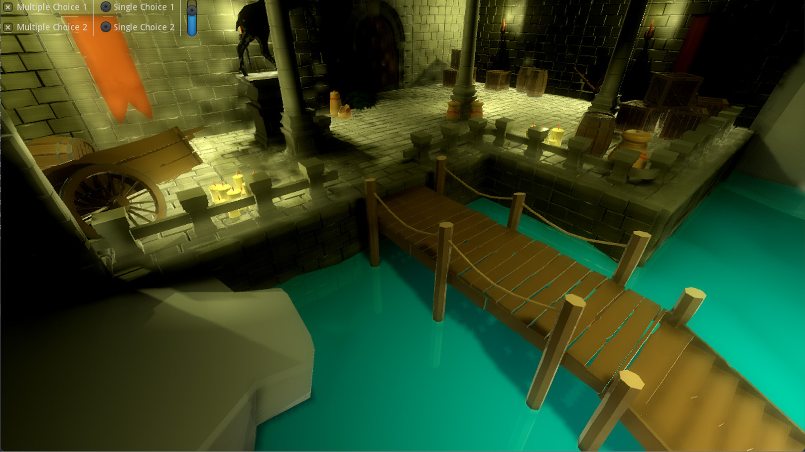
Figure 12.1 – The first run of our game
The UI decisions we have made are visible in the top-left corner of the game. We don’t need those for the moment. So, bring up the UI.tscn if you have it closed, turn off the HBoxContainer node, and run the game again. We’ll look into some UI concerns in the Detecting user input section soon.
Perhaps you’ve already noticed from the screenshots we have used in previous chapters or simply by looking at the project files that there has already been a Game.tscn scene configured as the main scene for the project. That’s why Godot did not ask you to pick the main scene when you pressed F5 since we had already assigned one to the project for you.
Open Game.tscn, and let’s see how this scene is structured. Everything might look self-evident, but there is the root node labeled as Game, then two child nodes labeled as Camera and Level-01. Evidently, the level we created in Chapter 9, Designing the Level, is a child node in Game.tscn. The other node, Camera, will be our main study area in this chapter.
We’ll split the rest of our efforts in understanding how cameras work mainly into two distinct areas. The most important topic is the projection type, which fundamentally changes the whole experience. We suggest this be something you decide early on in your own projects since any other tweaking can be done after this choice has been made. So, before we tackle individual camera settings, let’s see what kinds of projections there are.
Deciding on a type of projection
If you took an art class on learning how to draw architecture, this might be a topic you are already familiar with. The Godot version we are using comes with three types of projections. Although we will mainly focus on the first two, we’ll give a brief definition of all projection types, as follows:
- Perspective: This is the default camera projection where the farther objects are from the camera, the smaller they will look. Hence, two objects of the exact same dimensions will look like they are differently sized when one of these objects is placed away from the camera. This is also how human beings perceive the world, so if you don’t, get a check-up.
- Orthogonal: Also known as Orthographic, this type of projection renders objects of the same dimensions without altering their size, regardless of the distance to the camera. This type could give your game the dramatic look it needs. Also, there are some types of games—roleplaying (Fallout series) and Explore, Expand, Exploit, Exterminate (4X) (Civilization)—where this kind of projection is preferred.
- Frustum: This is a relatively new type of projection that has its uses in some types of games—for example, to get that 2.5D look some old-school games used to have where the visuals looked stretched. If you want to know more, https://zdoom.org/wiki/Y-shearing has some information about this topic.
In most cases, the first two projections we listed here will be enough. Maybe it would be better if we investigated their differences by experimenting. Since we’ve already seen the Perspective projection type, it makes sense to try the Orthogonal projection type, so follow these next steps:
- Select the Camera node in the Game.tscn scene.
- Change its Projection setting to Orthogonal and set its Size value to 6.
- Press F5 to run the game and notice a different artistic style.
After we make these changes, this is what we have:
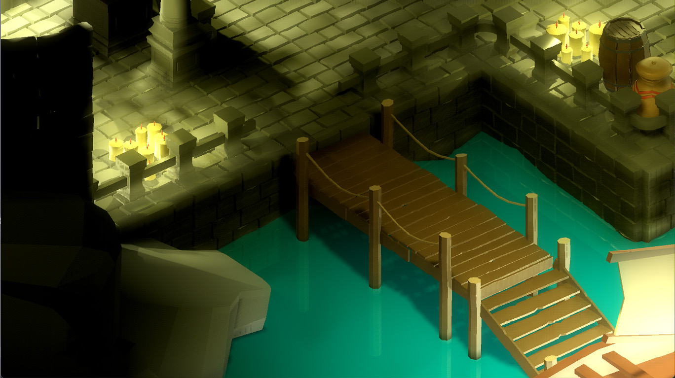
Figure 12.2 – Orthographic camera view from the same location
We picked a Size value that would make the render look close enough to the example we had in Perspective projection. The Size property is an interesting one because it takes into account many factors. For example, if you change the Keep Aspect value from Keep Height to Keep Width, you will have to double the Size value to 12. Most PC monitors, however, follow a landscape orientation. That’s why Keep Height is the default option, but if you are working on a mobile game, you might want to mix and match the correct Size value with the Keep Width option selected.
Camera-specific environment
While we are looking at different properties of the Camera node in the Inspector panel, now might be a good time to get a refresher on the Environment topic. In the Creating post-processing effects section of Chapter 10, Making Things Look Better with Lights and Shadows, we discovered how to create an environment that changed the look of the level. If you want to override some of the environment settings, you can do so by assigning a separate Environment object to the camera. The effects of both the level-wide and camera-specific environments will be combined.
No matter which values you pick for the right platform, one thing is obvious. Even though we didn’t move the camera’s position and rotation in the world, the effect we get is utterly different. Whereas we used to see the door in the back of the cave in the Perspective projection as depicted in Figure 12.1, the Orthographic view doesn’t permit us to see that far, as seen in Figure 12.2. When you compare both screenshots, the near elements are pretty much the same, but the Orthographic view simulates a more top-down look to the scene than looking far ahead.
Altering stuff in the Inspector panel and hitting F5 to see your changes in effect might get tiring quickly. While the Camera node is still selected, if you turn on the Preview checkbox, as seen in the following screenshot, you can speed up your workflow when you are editing your camera’s attributes:
Figure 12.3 – Previewing what your camera sees is handy, and it’s one checkbox away
This will let you preview what your camera is seeing while you are still adjusting its settings. Mind you, during preview, you cannot move around your scene freely. In fact, you can’t even select objects. So, remember to turn it off when you want to go back to editing your scene.
In light of what we have presented so far, what kind of projection type should we choose? We’re going to go with the Perspective mode. So, for now, revert your Camera node’s Projection setting to its default value. Since Godot decorates the Inspector panel with the relevant properties, the Size property will be replaced with the Fov property.
Let’s focus on this new property and some of the other changes we want to apply to the Camera node in the next section.
Adjusting the camera settings for our game
In this section, we are going to discuss a new term you have just been introduced to, Fov, and show which other settings we should apply to the camera. If you have been working on your own level design since the beginning, then the position and rotation of the camera we mention here will be meaningless. That’s why we’ll give you general directions to convey the spirit of the exercise. Also, hopefully, the screenshots you’ll see will help you align our level’s conditions to yours better.
First, a quick definition of the new term. Field of view (fov) is the angle, measured in degrees, through which a device perceives the world. Actually, if you consider your eyes as the device, your eyes also have a fov value. This is a highly technical domain, so we’ll offer you a few links in the Further reading section to discover it on your own.
For the time being, we’re much more interested in the practical applications of this subject since it’s pertinent to whether your game is running in portrait or landscape mode, or whether the game is for PC or consoles. The default value, 70, that Godot uses is a decent average value that will suit most cases. However, this default value also assumes you are going to run your game in landscape mode as it’s dictated by the Keep Aspect property, which is set to Keep Height.
Since players might have different monitor sizes and resolutions, the application has to pick either the height or the width as the source of truth (SOT) and then apply the other necessary transformations accordingly for the sake of not distorting the visuals. Sometimes, this practice will yield a result such as having a black band above and below the visuals. This method, known as letterboxing, is also used in the cinema industry for converting movies shot with a squarer aspect ratio to modern wider (from 4:3 to 16:9 or 16:10 ratio) screens.
If you hover over the Fov property in the Inspector panel and read the tooltip, you’ll see that there are multiple values you can set for this property depending on the aspect ratio your game will use. Thus, we’ll let you choose the best value for your condition. Nevertheless, we’re providing the following screenshot to demonstrate the permutations of different Keep Aspect and Fov values:
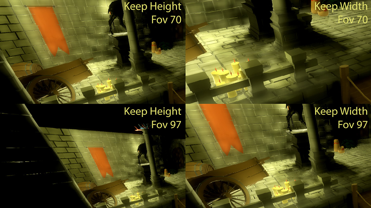
Figure 12.4 – Same camera position with different aspect-ratio constraints and fov values
What a big difference! Without changing a single thing for the camera, different permutations will yield lots of distinct results. Let’s wrap up the Fov topic by discussing what higher and lower values for Fov means so that you can make better decisions in your own projects.
At the end of the day, the Fov value you should pick will depend on the player’s viewing distance, which isn’t something you can really know ahead of time. However, there are conventions you can follow. For example, console games use a lower Fov value since it provides a zoomed-in-like view that compensates for the distance between the screen and the player. Most typically, a console game player will be sitting on a couch a few meters away from a screen that is usually large.
On the other hand, a PC player is usually less than one meter away from a monitor, thus it might be better to use higher Fov values. This increases immersion since players feel they get to see more of the world by virtue of having this view a bit zoomed out compared to lower Fov values. That being said, it’s known that really high Fov values also create motion sickness. When your brain is forced to process too much of the world, you get that churning stomach feeling, especially in first-person shooter (FPS) games.
Fov calculator
There is a handy calculator for finding ideal Fov values: https://themetalmuncher.github.io/fov-calc/. Select the aspect ratio and orientation of your screen, and the calculator will eliminate some of the guesswork. Obviously, if you let your players change their screen resolution in the game’s settings, you’ve got to programmatically update the Fov value the game uses.
To finish off this section, we’ll stick with the value of 97 for Fov and choose Keep Width for the aspect ratio since it works out better artistically. Also, since this level is so small, having the camera follow the game character won’t be necessary. Still, we could try to pick the best angle and position of the Camera node to see most of the scene. As already mentioned, our values won’t mean much. However, try to change the Translation and Rotation Degrees values for the Camera node to match what you see here:
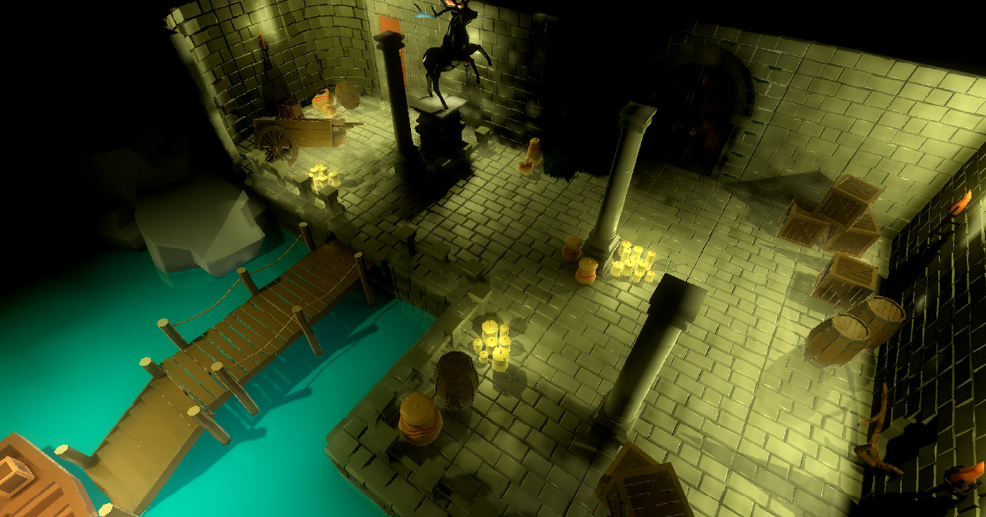
Figure 12.5 – The camera’s final resting position
What this view will give us are a few things. First, it covers the most crucial angles. Clara can only walk to certain spots on this level. Also, not every walkable location is important. Still, there doesn’t seem to be anything significant left out from this perspective.
Second, referring to her uncle’s note, there is a backpack behind the broken cart. It’s hard to see it from here because the sconce’s light in that corner is not enough to make the backpack all that obvious. All of this is intentional because we’ll want Clara to hold a torch in her hand, so that extra bit of light will be enough for her or the player to notice an important object.
Eventually, we expect the player to see and interact with the objects in the world, especially the backpack since it holds the key to the upstairs. A common instrument game designers use for player-to-world interaction is mouse events, which is what we’ll discover next.
Detecting user input
Mouse events are one of the many types of user input you can detect in a video game. Other most common types are keyboard or game controller events, which won’t be covered in this book. Still, the principles in detecting what the mouse is doing are similar to how you can treat other types of events. The reason why we are focusing more on mouse events is that there is an extra layer of complexity you’ve got to deal with, which is what this section will be about. Let’s dive right in.
In a conventional desktop application such as text- or video-editing software, the interface is usually populated with a lot of buttons, menus, and likewise. The natural behavior you’d expect from the users of such software is to click these designated spots, which is something the creators of the application anticipate and prepare for you. How would you go about this in a 3D game, though?
See, when you click anywhere on your screen, you are essentially clicking on a 2D surface. Thus, it originally makes sense to define the click’s coordinates based on the x and y axes. Let’s make the case even simpler. We are not clicking anything fancy but just the middle of the screen. By knowing the monitor’s resolution, we can do the calculation and come up with coordinates that are half the resolution in both axes.
Let’s imagine, in this special case where we keep clicking right in the middle of the screen, we have the game world we see in Figure 12.5. Where does that click correspond in our level? Even more interestingly, if you implemented a camera that moved elsewhere, perhaps even rotated due to gameplay reasons, how do you map the same x and y coordinates to a different position in the 3D space?
This is a challenging topic that is not always straightforward to resolve, but let’s see which techniques we can use to discern mouse events.
Knowing where the player interacts
There is a common technique in the industry for detecting where the player is pointing in a 3D world. It’s called raycasting, and YouTube is awash with tutorials dedicated to this particular topic, not just for Godot Engine but for other game engines as well. It assumes that you are casting a ray from where you clicked on your screen to a position in the 3D world. Since the game engine is already capable of rendering the game by considering the game objects’ positions in relation to the camera, which happens to be your screen, then the calculations are already done for you, to a certain extent.
Although this technique puts you in the right direction, you still have no idea which object in the path of that ray is the one you want to select. Perhaps an unfortunate analogy for a ray might be a strong enough bullet that’s traversing through all objects it connects with. So, if raycasting brings up many results, you’ve got to eliminate the ones you don’t want. Fortunately, there is a more direct way.
It would be convenient to only assign detection logic to the objects we want. For example, we can introduce a new model to our scene—a parchment, to be specific—right on the wooden slats of the pier. Once the player clicks this object, we’ll trigger the note currently hidden in the UI.tscn scene. Via this effort, you will also practice some of the methods you used in earlier chapters too. Here are the steps to take:
- Make a new scene out of Parchment.glb and save it as Parchment.tscn in the same folder.
- Since there is a default environment in effect, the scene will be dark, and it will be hard to follow the succeeding steps. To disable it, open Project Settings and clear the Default Environment field in the Environment section under the Rendering header. Close Project Settings to go back to Parchment.tscn.
- Add a StaticBody node under the root node.
- Add a CollisionShape node under this last node you introduced and assign a New BoxShape to its Shape field in the Inspector panel.
- Expand this new shape by clicking it. Type 0.15, 0.14, and 0.06 in the Extents section’s X, Y, and Z fields respectively. This shape should encapsulate the model.
- Still for the CollisionShape node, expand its Transform header, then type 0.05 in the Z field under its Translation section.
We are not done yet with the parchment scene, but let’s take a break and explain what’s happened.
We have added our first PhysicsBody type of node to our workflow with a StaticBody node. There are other types too, such as KinematicBody, RigidBody, and likewise, if you would like to offer physics-based gameplay. Since the parchment object we will place in the world won’t go anywhere, we chose StaticBody.
Then, we assigned a collision shape to the StaticBody node. Adding collision to game objects is necessary if you want the engine to detect when your objects collide with each other. By doing so, the game engine can determine these objects’ future trajectory and speed.
One type of collision the game engine can detect is when players interact with objects using input devices. For instance, the player might move the mouse over an object, click this object, or even want to drag and move it somewhere else. Out of all these possibilities, we are only interested in detecting when the player clicks the parchment model. We’ll learn how to distinguish the exact event we want in the next section.
Distinguishing useful mouse events
We’ve constructed all the necessary mechanisms to start detecting collisions. The basic shape we wrapped the parchment model in will act like a sensor to know if collisions are occurring. Out of so many different types of collisions, we are mainly interested in listening to mouse events, and—more specifically—detecting mouse clicks.
We’ll treat this click on the parchment as a precursor to bringing up the currently hidden Panel node inside the UI.tscn scene. Ultimately, we will build a communication line between the parchment and the UI.tscn scene. First, let’s see how we capture a collision and filter out the right type so that we can later trigger the chain of events we want. Here’s what to do:
- Attach a script to the root node in Parchment.tscn and save it as Parchment.gd.
- Select the StaticBody node and turn on the Node panel.
- Double-click the input_event entry under the CollisionObject header.
- Press the Connect button in the pop-up menu. This will add a few lines of temporary code, so change the Parchment.gd script to what you see here:
extends Spatial
signal show_note
func _on_StaticBody_input_event(camera, event, position, normal, shape_idx):
if event is InputEventMouseButton and
event.pressed:
emit_signal("show_note")
We’re now, in theory, tracking the input event on the StaticBody node. However, in practice, since the collision shape for generating this event is positioned precisely over the parchment, our setup will behave as though you are detecting clicks on the parchment itself. The following screenshot shows our progress in the editor:
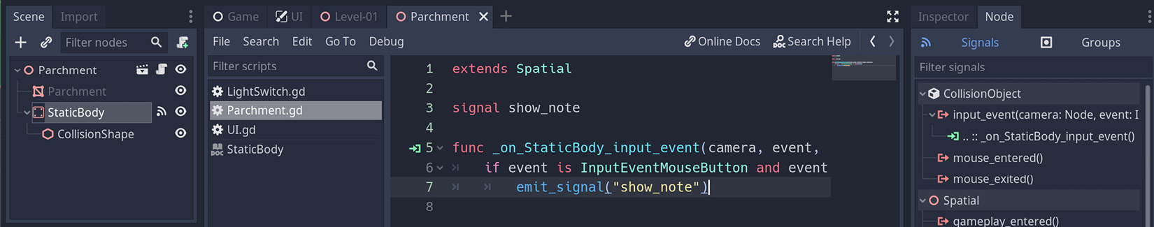
Figure 12.6 – We are attaching input events to the parchment object
The input event we are capturing is generic enough, but we are filtering it out so that it will be valid only in mouse-click conditions. Then, we transformed the meaning of this click by emitting a show_note signal, but who is listening to this call? Some construct out there could make sense of this signal—more specifically, the Panel node inside the UI.tscn scene. Let’s connect them next, as follows:
- Open UI.tscn and attach a script to the root. Save it as UI.gd and add the following line of code:
export(NodePath) onready var note_trigger = get_node(note_trigger) as Node
- Open Level-01.tscn and create an instance of Parchment.tscn in the Props group. Position this new node on the wooden slats of the pier so that it sits relatively close to the boat.
- Select the UI node in the Scene panel. There is going to be a Note Trigger field for this node in the Inspector panel. Press Assign… and select Parchment among the options that come up in the pop-up menu.
- Go back to the UI.gd script and add the following lines of code:
func _ready():
note_trigger.connect("show_note", self,
"on_show_note")
func on_show_note():
$Panel.visible = true
There is a lot going on here with a few lines of basic code. First, we prepared a field for the UI node to accept another object as a trigger so that we could assign the Parchment node using the Inspector panel. Then, we instructed the UI node to listen to a specific event—the show_note signal—so that it could trigger the on_show_note function. When this function runs as a result of the player’s click on the parchment, the Panel node, which is essentially Bert’s note, will become visible.
When you were building the UI in Chapter 11, Creating the User Interface, if you didn’t center the Panel perfectly, you can do so now by using the Layout button in the header of the 3D viewport. If you prefer, you can position the Panel anywhere you want. Ultimately, when you press F5 and run the game, after you click the parchment on the pier, you will see something like this:
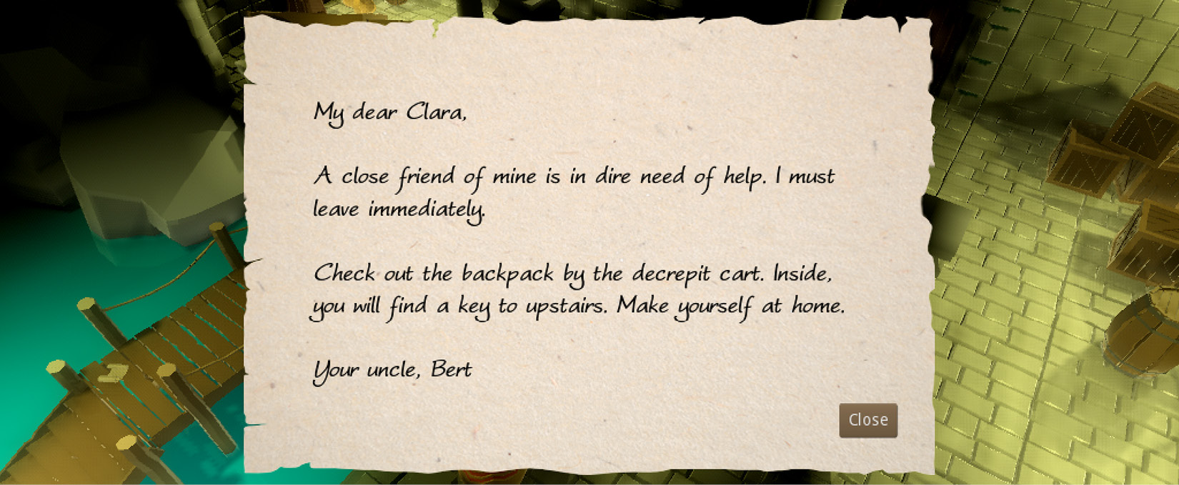
Figure 12.7 – Bert’s note to Clara was opened when the player clicked the parchment
Remember that the Close button is already wired, so it’ll close the note when you press it. If you do so, you can open the note again by clicking the parchment. Who knew that a simple mouse click could mean different things? In one context, it’s pressing on a flat surface that translates to clicking a 3D object, which then triggers other game systems. In another, it’s pressing a UI element like a button.
Sconces and candles
If the player is able to click the parchment, can’t they click the sconces and candles around the level? They can, but they won’t get a reaction out of it right now since you have to construct a collision structure, just as we did for the parchment. This is something you can work on as an exercise.
We’re not planning to have an inventory system in our game. However, in games that employ that kind of functionality, it’s common to see that parchment disappear from the world and find a place for itself in the player’s inventory. Then, the player can later click an icon that represents the note in their inventory to bring up the note UI again. In this extra case, your UI structure would also have to listen to a show_note signal emitted from a different structure, but it’s a similar principle.
Not having an inventory system is not a real detriment to our workflow at this point since we have more pressing issues such as helping the player move around. Although we have a level where there is a solid floor, we have no game character that can stand on it. We’ll look at how to introduce one and move it in the upcoming section.
Moving the player around
You might have heard that context is important in real life because context can make an ordinary word or statement look especially bad or fun. This is consistently true in most technical areas—more specifically when we try to describe visual or artistic aspects. Sometimes, it’s alright to use words interchangeably, but making a distinction might be crucial—even necessary every now and then. For example, at the end of the last section, we claimed that we’d move a character. It might be an absurd attempt to do mind-reading via the pages of a book, but would we be wrong if you imagined a biped creature such as Clara walking around using her legs and swinging her arms?
Chances are you did think about it that way, but you’ll have to wait for that at this moment since we haven’t even moved an object between two spots on the level. Referring to the analogy of context, not every move has to involve a fully-fledged animation. Clara’s model, or an ordinary cube for that matter, could also move by following a path. Therefore, it might be more appropriate to think of movement and animation as two distinct topics. That’s why we will introduce animation into moving objects later in the Triggering animations section after we first tackle movement in this section.
Now that you know there is a difference between an object traversing a scene and doing so with an animation, the big question is: How to detect where to move an object? Let’s be more specific in terms of our level design. We have a pier where we have just recently placed a parchment. The basic expectation is that our player character will be standing right by this parchment. Once the player is done reading the note, we expect them to reach the backpack to acquire a key to unlock the door that leads upstairs. Therefore, we need a mechanism to do the following:
- Detect clicks
- Find a possible path
- Move the player to their desired spot
Before we can start working on these items, we first need two vital ingredients: Navigation and NavigationMeshInstance. These two nodes work hand in hand to designate some areas in the level to be walkable. After all, we wouldn’t want the player to walk everywhere or through objects, hence the importance of some of the props we placed around the level.
Interchangeability for the sake of brevity
Although we’ve pointed out a major difference between movement and animation and claimed that we can’t use these two concepts interchangeably, we are in luck when it comes to the two nodes we are going to peruse in this section. You’ll soon see that a Navigation node is practically incapable of doing its work without depending on NavigationMeshInstance. We’ll use Navigation as a general concept (unless otherwise specified) to talk about navigation, while technically, we might be describing the attributes of the NavigationMeshInstance node.
With that said, let’s create areas that are traversable by the player.
Creating walkable areas with a Navigation node
The level we started to design in Chapter 9, Designing the Level has some nice, but also troubling features. From a visual perspective, the props and their placement in the world look organic. Even bulkier objects such as the broken cart and the stag statue are out of the way but still in the line of sight when a person walks between the pier and the door. There is an element of usefulness mixed with clutter.
Speaking of clutter, when we introduce a Navigation node and ask Godot to calculate traversable areas, the location of the objects in your level may gain bigger importance. You may get a hint as to why this is after we make changes to the level, so open Level-01.tscn and follow along with these steps:
- Add a Navigation node in the root node. Then, add a NavigationMeshInstance node right under this last node you’ve introduced.
- Drag and drop the Floor, Columns, Rails, Props, and Dock groups under the NavigationMeshInstance node.
- Select the NavigationMeshInstance node and assign a New NavigationMesh to its Navmesh field in the Inspector panel.
- Click and expand this new property so that you can do the following:
- Type 0.18 in the Size field and 0.1 in the Height field under its Cell section.
- Type 0.4 in the Radius field and 0.2 in the Max Climb field under its Agent section.
- Turn on the Ledge Spans option under its Filter section.
- Press 7 on your numeric keypad to switch to the Top Orthogonal view.
- Press the Bake NavMesh button at the top part of the 3D viewport.
If your level design is different than ours, please try to follow the steps we have presented in the spirit they are given. This is especially important if you directly transfer our values to your system, which might not fit. In the end, you’ll see something similar to this:
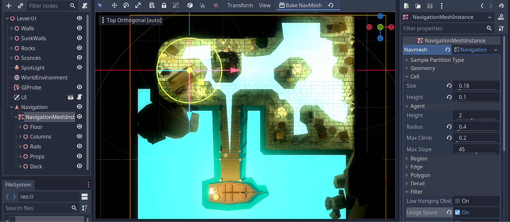
Figure 12.8 – We have introduced a NavigationMeshInstance node and configured it
Notice the light-blue overlay introduced by the Navigation node. That is all walkable as far as the engine is concerned. There is something awkward going on, though. When you dragged the Dock group into the Navigation node, the Water node came with it. So, it was also considered a candidate.
If this were a Dungeons & Dragons game, your player might know the Water Walk spell and be able to walk on the water mesh. There is no such spell in Clara’s world, but it’s something you might want to consider if your game allows for such a mechanism and flavor. Therefore, instead of removing the water altogether, it’s best if we changed its place in the hierarchy by doing the following:
- Move the Water node somewhere other than the NavigationMeshInstance node—for example, above the SpotLight node.
- Similarly, drag and drop Parchment out of the Props group.
- Select the NavigationMeshInstance node and press the Bake NavMesh button again.
With a different hierarchy, the newly baked traversable area should look like this:

Figure 12.9 – The water is no longer walkable thanks to being in a different hierarchy
By determining which areas should be included in the NavigationMeshInstance node and adjusting values in the Inspector panel, you can come up with a more precise layout. Ultimately, if you can throw a few obstacles in the player’s way before they reach important places instead of following a perfectly straight line, you will create more engaging gameplay.
If the layout in your level doesn’t look traversable in some key areas, such as the backpack near the cart, then move some of those props around and bake a new map. This is going to be important when we introduce movement logic.
You might want to rotate the view to Perspective if you want to get a better feeling of which areas are reachable. Speaking of which, who is going to walk these areas? Next, we should introduce the most basic player character before we get into more advanced character models such as Clara.
Introducing a basic player character
Earlier in this chapter, in the Knowing where the player interacts section when we were inquiring about how the player could interact with the parchment, we introduced a StaticBody node because the object wasn’t going anywhere. We also mentioned that StaticBody was one of many PhysicsBody options available to you besides two other commonly used nodes, as described here:
- RigidBody: Bodies that don’t have control over themselves fall under this category. The word rigid might be confusing at first since it conveys a feeling of how strong or flexible an object is. On the contrary, you can use a RigidBody node for simulating the motion of a soccer ball or a cannonball. You usually apply forces to objects that have this node, which will instruct how the physics engine will calculate their trajectory, collisions, and likewise.
- KinematicBody: Bodies that actually have control over how they will behave in the world fall into this category. Most typically, player characters use this node, but any system that creates its own motion—such as an actual engine or rocket—needs to use this.
Consequently, the best option we have is to use a KinematicBody node to simulate a player character. We’ll now follow the next steps to create a very simple one:
- Create a new scene and save it as Player.tscn under the Scenes folder.
- Start with a KinematicBody node as its root. Then, add a CollisionShape node and a MeshInstance node under the root.
- Select the MeshInstance node and do the following:
- Assign a New CapsuleMesh to its Mesh field. Expand this new field and type 0.4 for its Radius property.
- Type 90 in the X field in Rotation Degrees under the Transform section.
- Select the CollisionShape node and do the following:
- Assign a New CapsuleShape to its Shape field. Expand this new field and type 0.4 for its Radius property.
- Type 90 in the X field in Rotation Degrees under the Transform section.
- Select the KinematicBody node and type 0.9 in the Y field in Translation under the Transform section. Rename this KinematicBody node Player.
This will create a capsule shape, which is a quick way to simulate player characters. Also, we picked a collision shape that would go well with the mesh we created. Since there isn’t much to look at in the Player.tscn scene, it may be best if we show you where to place it in the world. Create an instance of it in Level-01.tscn, and position it as shown in the following screenshot:
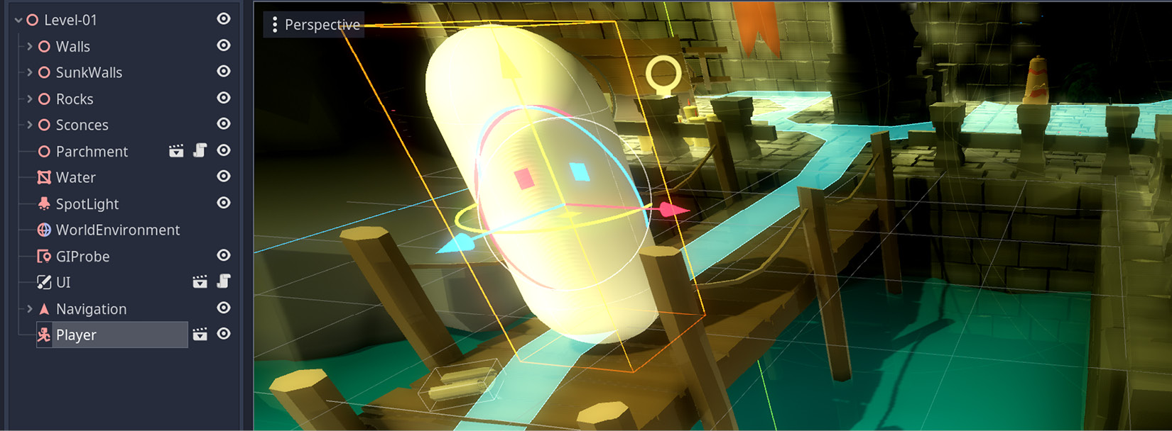
Figure 12.10 – An upright pill-shaped player character
The player character, although it looks like a pill standing up right now, is now part of the world and ready to move around. It just needs to be told where to go. How can we give it instructions before even we know where it’s supposed to go? To solve this mystery, we will have to prepare a structure to catch clicks. All this will eventually lead us to revisit a topic we dismissed earlier in the Detecting user input section: raycasting. After all, it will help us know where the player clicked in the world.
Preparing a clickable area for raycasting
When you know exactly which objects should be interactive and receive mouse events, the method we applied in the Distinguishing useful mouse events section is still valid. It entails anticipation on the game designer’s end, so the essential bindings could be done early on, as we saw. However, what if it wasn’t always possible to foresee this, or how viable would that method be on a larger scale?
For example, if we were to add a StaticBody node to each floor model we have used so far, we could certainly detect mouse clicks. That being said, sometimes, it’s a bit too late for that. Right now, our level has all the floor pieces as model instances instead of scene instances because, back then, it was convenient to drop the models and be done with the level design. We could still try to create a scene out of a floor model, but you’d still have to swap all the floor assets in the level. It’s a lot of work.
Since we already know that a StaticBody node is necessary to initiate an input response, we may yet use it to our advantage. Instead of attaching it to every single floor piece, we could designate an area as large as what all the floor pieces occupy, and detect the clicks on this large piece. Here’s how to do this:
- Add a StaticBody node to the level and place a CollisionShape node inside this StaticBody node.
- Assign a New BoxShape to the Shape field in the Inspector panel.
- Expand this new property and adjust its Extents setting. We used values such as 9, 1, and 8 but you might want to adjust these values after you finish the next step.
- Position the StaticBody node in the level so that the following applies:
- Its Y coordinate is roughly -1.05. Adjust it to a value so that its top almost aligns with the floor but just below the parchment. We’ll discuss this after we finish moving the player.
- Its X and Z values are at a point where its child, CollisionShape, encompasses the floor pieces and the walkable areas on the pier.
It might be easier to decide on the measurements if you switch to the Top Orthographic view. The blue square in the following screenshot represents the area we want to use as a click detector:
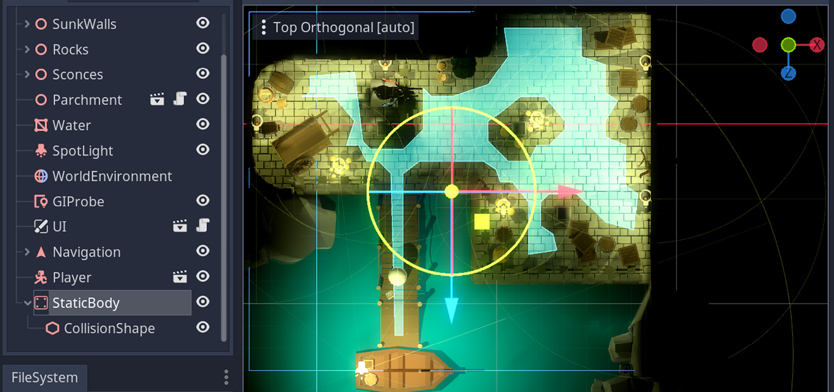
Figure 12.11 – The StaticBody node covers all walkable areas
You might be wondering if we overdid it with the detection area since Figure 12.11 clearly shows it is way larger than the walkable areas. A short explanation is that when you click on areas outside the traversable field, the pathfinding algorithm will take the player to a nearby spot but never to the exact position the player clicked. For example, if you click in the water, then the player character will move to the clicked spot as close as possible but still stay within the limits.
When you get to see the code, things might make more sense from a technical point of view. With that said, let’s attach some code to the player character so that it can move around, as follows:
- Open Player.tscn and select the root node.
- Attach Player.gd from the Scripts folder to the Script field in the Inspector panel.
Let’s explain the most important parts of the code we have just applied. You can refer to this code block at https://github.com/PacktPublishing/Game-Development-with-Blender-and-Godot/blob/main/Chapter%2012/Resources/Scripts/Player.gd. The first 10 lines are for storing some of the startup values and structures we are going to use. Three of those variables are worth a thorough explanation since the rest is self-explanatory. Let’s look at them in more detail here:
- camera: The player scene has no Camera node, but it needs to access a camera to do the raycasting. So, we appropriate the currently used camera as a workaround.
- space_state: This is our entryway to Godot’s PhysicsServer node that monitors which objects collide or intersect with each other. We’re going to use this variable to know if a click connects with the floor.
- nav: Since the Player node will be part of the Level-01.tscn scene that also holds the Navigation node, we use a mechanism like this to inject the Navigation node into the Player node. This way, the Player node can query the Navigation node to find a possible path.
The rest of the script consists of four functions. Despite that, two of those functions are doing the heavy lifting because the _input and _physics_process methods are essentially offloading their tasks to two other functions: find_path and move_along respectively. We could have ignored these latter functions, but when you are able to separate distinct functionality into their own functions, you should do this to keep your code clean.
All of this was done so that we could do a raycasting that is implemented in the find_path function, which is what we are going to study next.
Using Navigation node for pathfinding
The large StaticBody node we’ve added to the scene is still not enough to know at which point on the floor the click happened. Having just that will only let us know that the player clicked somewhere in that area. So, in the end, we are still going to use raycasting for finding the precise location so that we can begin constructing a path toward this position.
To that end, the find_path function in the Player.gd script is going to use the following two techniques:
- First is raycasting, to know exactly where the player clicked
- Second is whether there is a possible path toward that position
The first three lines of code in the find_path function, as shown here, are what raycasting is about:
var from = camera.project_ray_origin(event.position)
var to = from + camera.project_ray_normal(event.position) * 100
var result = space_state.intersect_ray(from, to)
Firstly, we ask the camera system to tell us from where the ray is going to originate. Hence, we store it in the from variable. This happens to be where the mouse event happened. Keep in mind, though that this event is still on our monitor’s 2D surface. There is still no notion of where we are clicking in the 3D world.
Secondly, we ask the camera system to let us know where a ray would go if we projected it 100 units from into the world. Now, we know where to stretch the ray. Still, there is no guarantee that this ray will hit anything. Thus, we check if anything is intersecting the ray, and store it in the result variable.
So, in just three lines of code, we determined a line between where we clicked on our screen and a position in the world. The result of this raycasting might be empty, so it would be prudent to check if there is an object colliding with our ray. Only then can we proceed with finding a path.
This is where the nav variable comes into play. Since it’s a reference to the Navigation node in the level that knows the player’s position and where the player wants to go next, it calculates a simple path between these two spots. Ultimately, a series of 3D coordinates are stored in the path array.
Separation issues
In a situation such as the pathfinding operation requiring a raycasting done in the find_path function—in other words, when two systems are closely related to each other—it might be okay not to separate the raycasting logic into its own function. We’ll revisit this concept later when we work on a more advanced game character in the Triggering animations section.
Sooner or later, you’ll have a walkable path, although this doesn’t automatically make the player character follow a path. We’ll need several more lines of code to do that.
Moving the player to their desired spot
We have used raycasting to detect a spot where the player wants to go and queried the Navigation node to find the closest path to this desired spot. We are now ready to instruct the Player node to move between different points along the path.
The move_along function in the Player.gd script receives a path and processes it one step at a time. Since it’s unlikely to have a straightforward path between the start and end points, the path will be composed of a series of midpoints before the player reaches their last stop. It’s like walking in real life where you make course corrections before you arrive at your destination. Naturally, if the path is empty or all of its steps have been processed, we terminate the function early.
Otherwise, we move the player between two stops by checking if the distance to the next step is within a certain threshold. Speaking of this threshold, this might be a good moment to talk about a caveat. During the writing and testing of this code, we had moments where the threshold value should have been 3, or sometimes, 1. You might want to experiment with a different value if you notice the player character is behaving awkwardly. This is something that will be remedied in later versions of Godot, as is noted in the official documentation:
After all this hard work, we are now one step away from having the player character move around, so let’s carry on with this, as follows:
- Switch to Level-01.tscn and select the Player node.
- Using the Inspector panel, click the Assign… button in its Nav field to select the Navigation node in the upcoming pop-up screen.
- Press F5 and click on different spots in the level.
When we test the scene and move the character away from the pier, this is what it looks like:
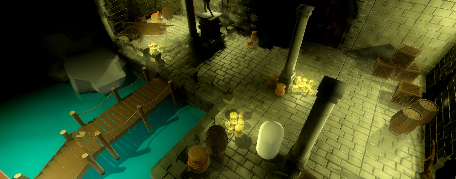
Figure 12.12 – The player character can now move in the world
You now must be able to move the player character around by pressing on the floor or even in the water. The nearest spot will be picked as a destination. Also, while you are moving around, try to click the parchment on the pier. If it is placed just so it’s below the catch-all StaticBody node, then you won’t be able to trigger the note. If that’s the case, either adjust the Y position you set in the Preparing a clickable area for raycasting section for the StaticBody node or move the Parchment node up in the Y direction.
As long as the clicks are not competing, the parchment will trigger the note. If the player character is away, it will then move near the parchment as soon as the note is open. You might notice odd behavior at this point if you click the Close button. The note will close as expected, but the player character will suddenly move just under where the Close button was. It’s as if the note UI is letting some of our clicks through and the pathfinding logic picks up that call.
Fortunately, there is a quick fix for this kind of behavior. If you replace the _input function with _unhandled_input, then all will be well. If these two look alike and unclear, you might want to find their nuances in the manual: https://docs.godotengine.org/en/3.4/classes/class_node.html. It might be worth remembering its use for quickly fixing a lot of UI headaches.
Wrapping up
If you have been developing video games for a while, you might already be familiar with the notion of iterative and incremental workflow. For example, it’s been okay to have indestructible crates so far. Let’s examine a scenario where you now want these crates to be destructible.
Not only do you have to account for certain conditions to happen, such as if the player has the right item to break the said crates, but you will also have to prepare animations to be triggered at the moment of destruction. These are both programmatical and artistic changes, and they can definitely be done with ease to a certain extent. When you baked the walkable areas, the Navigation node believed the crates were solid obstacles. However, in this new dynamic situation, you also have to update the NavigationMeshInstance node with the new conditions.
If a crate the player has just destroyed is no longer part of the world, and that particular area should indeed be walkable, you have to update the walkable areas by baking a new map. Fortunately, it’s possible to create multiple NavigationMeshInstance resources and save them on the disk so that you can swap them to accommodate dynamic cases as needed.
Sometimes, it makes more sense to move ahead with prototypes. For instance, it was good enough to have our player character look like a capsule to test movement logic. It would be nice to have our avatar look more like a person than a white pill. Let’s see how we can accomplish that next.
Triggering animations
In Chapter 5, Setting Up Animation and Rigging, we tackled the creation of animations in Blender. Then, in Chapter 7, Importing Blender Assets into Godot, we saw how to import a model into Godot Engine and use the AnimationPlayer node to test the model’s different actions. The steps we’ll present in this section should be enough to introduce Clara to the game, but if you need a reminder on how to create and import animations, you might want to seek out those two chapters.
Since we are done with the player’s movement, what is missing is to introduce Clara to our workflow and play the proper actions, such as idling while she’s standing and walking while she is moving around.
We’ve already created a basic player character when we constructed Player.tscn and attached a script to this scene. It’s primitive but the scene structure is a good starting point. Follow these steps:
- Click Clara.glb in FileSystem, then bring up the Import panel.
- Select Files (.anim) in the Storage dropdown under the Animation header. Refer to the Separating actions section from Chapter 7, Importing Blender Assets into Godot, to remember the need for this step.
- Press Reimport to set up Clara’s dependencies properly. Switch to the Scene panel.
- Open Player.tscn and delete the MeshInstance node.
- Drag Clara.glb from FileSystem onto the Player node. Thus, the old MeshInstance node will be replaced with a Clara node.
- Click the root node and zero its Translation values since the values that applied to the basic capsule-shaped player are no longer valid.
- Adjust the CollisionShape node’s Shape field in the Inspector panel so that it encapsulates Clara. We haven’t changed the Radius setting but set its Height value to 1.2.
The main goal here is to replace the old MeshInstance node with Clara and adjust the CollisionShape node so that collision detection is done correctly. The editor should now look like this:
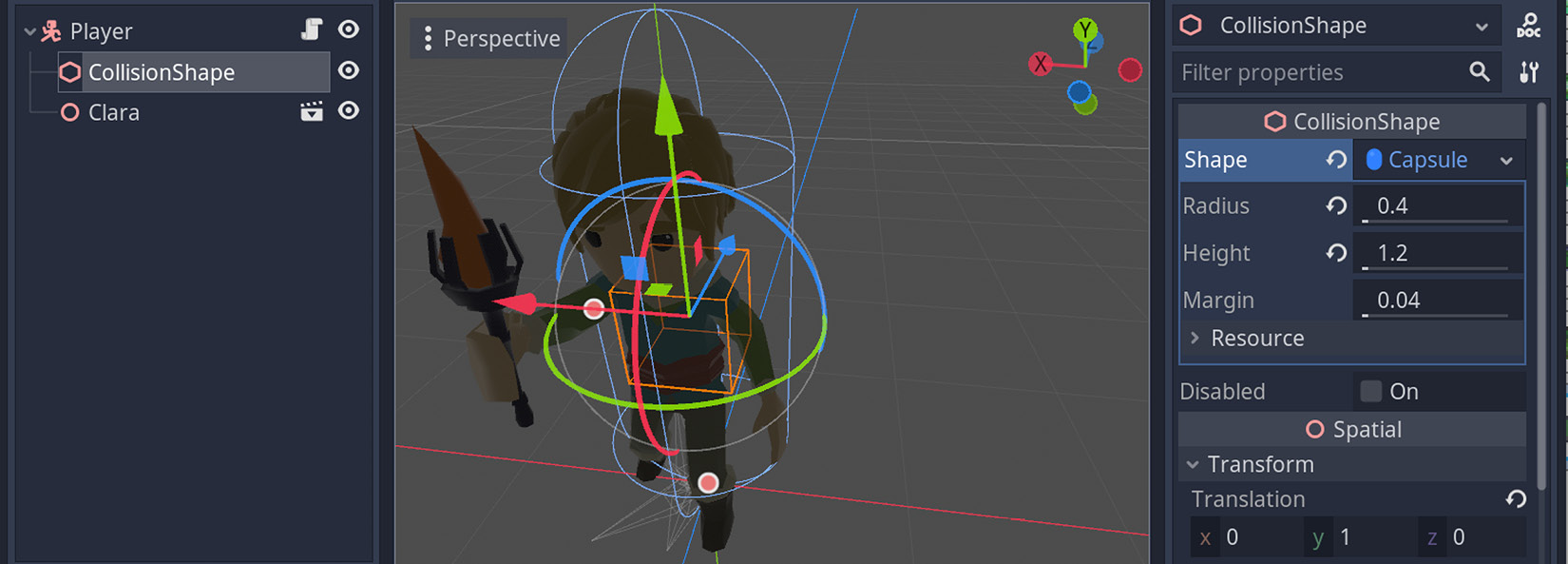
Figure 12.13 – Clara has replaced the boring MeshInstance node
With this method, you can easily test your code for a player character, and then replace the test model with the actual model later. This might be useful if you are the main developer and you are still waiting for the artwork from your colleagues.
Improving the looks of the avatar was a good step forward. It’s looking much more appealing. We will do the same for its movement because you might notice odd behavior if you run the game now. Clara will be moving around like the old capsule mesh because it’s missing two major qualities, as follows:
- Looking in the direction it’s currently moving
- Showing signs of walking instead of looking like a stick sliding on surfaces
There is also another problem but it’s so minor you can fix it without needing much discussion and explanation. The Player node, which used to hold the simple MeshInstance node, had to be moved slightly higher in the world. You can lower this new Player node to the level of the pier so that Clara’s feet are connecting with it. If you don’t make any changes, Clara will look like she’s hovering and then moving diagonally as soon as her movement logic kicks in.
For the other two major concerns, we’ll have to dig deeper than just changing an object’s position. We’ve got to first update the script we are using for the Player node, though, so here’s what we need to do:
- Select the root node in Player.tscn.
- Swap its script with Clara.gd from the Scripts folder.
- Press F5 and enjoy seeing Clara walking around as a normal person should.
Rejoice—she’s walking!
How did it happen so quickly? We will devote the rest of this section to discovering which changes the Player.gd script has received to accommodate the new behavior we are experiencing and—undoubtedly—enjoying.
Understanding how Clara looks around
An incremental and iterative workflow is the short and non-technical answer to understanding how Clara looks around, and it’s something we advise you to keep in mind when tasks seem monumentally big at first. For example, we were initially concerned with basic movement, which was achieved within the Player.gd script. At some point, when you know basic test systems are working, it’s time to take things to the next level. That’s what happened with the Clara.gd script.
We’ll now explain the steps we have taken to turn the basic sliding movement into a more elaborate walking animation. As far as having new variables is concerned, we are using a simple flag: is_moving. We keep track of this flag in order to understand whether Clara is moving or not. The use of this new variable will soon be discussed in the context of some other changes we have made.
New term – flag
In the programming world, a flag is a variable that means a certain condition has been satisfied. It’s often used to determine a system’s behavior, like an electric switch with a false/true or off/on states, hence they are often called Boolean flags. However, it is possible for a flag to have different kinds of predetermined values.
A natural behavior for Clara would be to look in the direction the mouse cursor is. Let us remind you, once more, that although the cursor is moving over our monitor’s 2D surface, we need to do essential projections into the 3D space to find the proper direction. We were already doing that in the find_path function inside the Player.gd script. Since we now want a similar raycasting done for determining where Clara is supposed to look, we extracted those common lines from find_path to its own function, get_destination.
Hence, the more common uses and repetitions you can find in your code, the better it is to separate them into their own functions. This was something we intentionally ignored in the Player.gd case for simplicity’s sake. However, we now have both the find_path and turn_to functions depending on get_destination.
Just as find_path is piggybacking on the _unhandled_input function, the turn_to function is also using the same mouse event. Speaking of the turn_to function, let’s take a closer look at it here:
func turn_to(event):
    if is_moving:
        return

    var direction:Vector3 = get_destination(event) *
    Vector3(1,0,1) + Vector3(0, global_transform.origin.y,
    0)
    look_at(direction, Vector3.UP)
First of all, although we haven’t yet seen where the moving flag is set, if Clara is moving, we wouldn’t want her to keep looking around. So, we have an early return statement to terminate the turning behavior. Then, once we determine a suitable direction via the get_destination function, we trigger Godot’s built-in look_at method.
The logic is simple, but the math to determine the direction vector in turn_to might need a bit more explanation. Normally, the value from get_destination would have been enough, but we seem to be multiplying the return value with another vector and then adding it to another vector. This is because the destination given by get_destination also includes the y axis in the 3D space. We want Clara to keep her posture the same; in other words, we don’t want her to look up or down. Those two vector operations are required so that she doesn’t rotate in an awkward way.
You can see the weird behavior yourself by removing the vector operations and only keeping the get_destination function. When you move your mouse cursor near Clara’s body, she may suddenly pivot around her feet and sometimes even flip upside down or sideways. The intricacies due to projections between 2D and 3D are something you’ll have to account for in the future, and it’s a common occurrence in controlling game characters.
It’s nice that Clara is facing where the mouse cursor is. It’s also a separate mechanism because she can do so without moving, as you may have already tested with the preceding code block. It would be nice if she kept looking where she was going while walking. This will be done in the enhanced version of the move_along function. Let’s see how we improved it in this new version.
Adding a looking behavior to moving functionality
It is nice to see Clara looking around while she’s standing still, but we will also want her to face the destination she’s walking to. For example, if you click near the crates by the wall (more like the right-hand side of the screen), she should walk straight until she clears the pier, then turn and look right, and then keep walking. Similarly, while she’s in this new spot, if you click somewhere far away such as near the stag statue or the pier again, she should turn around and walk back in a natural way.
This kind of behavior can easily be added inside the move_along function. The way it is, that function already determines how many steps there are left along the path Clara should take. As she’s walking toward the point on the path, she may as well look at where she is going. That’s why we have a simple look_at function call after move_and_slide in the move_along function.
Other useful KinematicBody functions
We have been using the built-in move_and_slide function of the KinematicBody class. There is a useful function in the same class that might be helpful in levels where the player would like to reach an elevated location by following a slope: move_and_slide_with_snap. Similarly, you might want to check whether the player should perform the next move. If that is the case, the test_move method might be handy.
Also, the fate of is_moving gets decided in the following lines of code:
if !path or path_index == path.size():
    is_moving = false
    $Clara/AnimationPlayer.play("Idle")
    return
is_moving = true
Notice that, similar to how we do it in Player.gd, the if block checks whether there are steps left along the path. It’s exactly at this point we can set the state of the is_moving flag. Consequently, unlike the original version, the new move_along function’s if block is making sure the moving logic is turned off when there is no path left for Clara to walk.
If the player clicks a different spot and there is a new path determined, then we turn on the moving flag. As long as there are midpoints for Clara to follow, she’ll follow the same steps we’ve described—face the right direction, walk the necessary distance, face the next direction, walk, rinse, and repeat—until she no longer has any more steps to take.
Besides deciding on the state of the is_moving flag, there is something else going on in that if block in regard to animations. Let’s focus on that in the next part.
Playing the right action for Clara
We’ve already seen how actions are related to animations in the Separating actions section of Chapter 7, Importing Blender Assets into Godot. They are like what atoms are to molecules. So, when we want to trigger an animation for a model, we actually mean to trigger a particular action. We’ll finally utilize this notion and put Clara in action.
We have seen how the improvements we made to the Player.gd script have added extra flavor to Clara’s behavior. That being said, she could also benefit from a touch-up in the animation department. That’s precisely what’s also happening inside the move_along function.
We already know how to determine whether Clara should move or not, and we are keeping track of that with the is_moving flag. Subsequently, that’s the right moment to trigger the required action for her. Thus, when she’s no longer supposed to move, we trigger her Idle action. Conversely, the Walk action is activated when is_moving is set to true.
When we made Clara.glb part of the Player.tscn scene, and it turned into a Clara node, an AnimationPlayer node already came within it with all of Clara’s actions set up. The code we have written so far is aware of exactly where this AnimationPlayer node is in the internal structure. Should you import a different model with a different Scene tree, then you might have to alter your code to find the right path to the AnimationPlayer node.
It’s hard to convey an animation via the static pages of a book, but when we move Clara near the column approaching our camera, this is what it looks like:
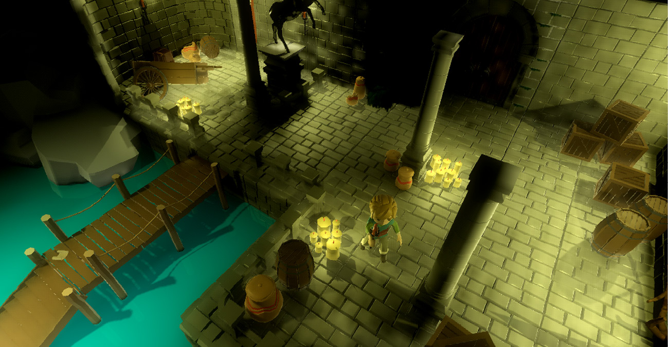
Figure 12.14 – Clara can now move around the level
Also, notice how the light conditions in the scene are affecting her model when she walks in darker and brighter spots. In the next chapter, we’ll turn off some of the light sources. So, as she or the player is walking around, we can use the torch she’s holding to illuminate the scene.
We couldn’t finish the animation topic without mentioning an advanced subject: blending animations. We will not cover it in great detail, but it is worth mentioning it for more advanced cases of animations you would like to use in your projects.
Blending animations or actions
After a while, the names that are used in most computer-related things may start to seem like they have something to do with each other. We used Blender in the first several chapters to build assets, textures, animations, and likewise. The blending we are now going to talk about has nothing to do with Blender itself.
Our point-and-click adventure game is very simple so far. Clara plays the Idle action while she’s standing still, and she uses the Walk action when she’s moving. Although her model contains other actions such as Death, Run, and likewise, we aren’t going to use those. If you want to take this project and move it further, you can accommodate different needs a player may have by improving the Clara.gd script and incorporate these other actions.
At some point, when you have a much more complex system where the actions you are triggering come to an end to give room to another action, you may notice that these actions abruptly start and end. Then, imagine how the crossfade functionality in an audio player makes the whole experience more pleasant when a song track changes to another. What if you had a way to transition the end of an action smoothly to the beginning of the next action? You can easily achieve that for animations with the AnimationTree node.
Unfortunately, the page count is limited for us to cover such an advanced topic. That being said, the official documentation has a nice and long tutorial page dedicated to this very subject. It also comes with plenty of animated GIFs that you can’t possibly experience on the static pages of a book. So, in the end, you might be better off exploring how to blend animations by following the instructions at https://docs.godotengine.org/en/3.4/tutorials/animation/animation_tree.html.
Blending animations is heavily used in high-pace action games when transitioning between different attack and run states should look more seamless. In our current situation, we are not missing out much by not having this kind of functionality.
We have made great strides so far in our point-and-click adventure game. Let’s wrap up and count our victories.
Summary
This chapter finally covered the long-due camera topic we’ve been waiting to tackle since Chapter 4, Adjusting Cameras and Lights. You now have multiple options to choose from, from a simple Camera type to an InterpolatedCamera type that follows a target. Should you want to get fancy and dip your toes in VR, you also have ARVRCamera at your disposal.
As you now had a proper camera showing you the game world as opposed to seeing things within the editor, it was the right time to investigate how to interact with the world itself. To that end, we presented raycasting as a possible solution but quickly dismissed it in favor of using collision detection, which provides more flexibility and precision. We used this technique to detect a click on a specific game object: a parchment. During this effort, you used signals as a way of interpreting the player’s click as a trigger to turn on the note.
Next, you looked into creating a simple game character and moving it around the level. Sometimes, the game design is missing key elements, and other times, the level might need some more help. Once you, as a solo developer or as a team, are happy with the direction the game is going, then you can up the ante by introducing more complex systems.
That’s exactly what happened in between testing Player.gd and improving it with the more advanced Clara.gd script. In the end, you were able to find a suitable position in the world for Clara to move and do this by using the proper animation cycle. Since you’ve covered the essentials, it’s now up to you to enhance the script if you want to use more actions and special conditions for player interaction with the world.
In the next chapter, we’ll introduce a few more tools that will add to the interactivity we have been building, such as playing sounds, conditionally triggering certain events, and switching to another level.
Further reading
Although we taught you how to technically set up a camera, there is a whole other artistic side to picking the best camera settings. You might want to check out online courses and books that cover topics such as composition and storytelling. A few examples are provided here:
- https://www.udemy.com/course/composition-and-perspective-for-stunning-visual-art/
- https://www.learnsquared.com/courses/visual-storytelling
- https://www.learnsquared.com/courses/production-concept-art
- https://www.cgmasteracademy.com/courses/93-composition-for-concept-art-and-illustration/
If the code in the Player.gd and Clara.gd files look very similar, and if it’s hard to compare line by line, there is an online tool you can use that can help you see and highlight the differences: http://www.tareeinternet.com/scripts/comparison-tool/.
Our game doesn’t involve enemy characters that follow our player, but it will follow a similar approach. For example, once the enemy detects the player, it will also have to do pathfinding for finding the player’s position and moving toward it. A lot of video-game AI books cover player detection and seeking topics such as the example we gave. So, since most AI topics are generally universal, don’t shy away from reading a wide variety of material. You can always apply the insight you gain elsewhere later in your Godot projects.