
9
Designing the Level
From this chapter on to the end of this book, you’ll be actively working on creating a point-and-click adventure game. We’ll show you the necessary steps to create a game in which you’ll place and command a character whose name is Clara. Players will be controlling her actions inside a cave that will be initially dark, but you’ll be able to give controls to the player to change the conditions of the lights. Once you figure out how to move her around in the world, you’ll also place trigger points in this cave so that the world reacts to Clara’s actions to make things interesting but also challenging. This part of this book will cover enough basic building blocks for you to start practicing building small-scale adventure games.
Through all these efforts, you’ll learn how to utilize different parts of Godot Engine, especially the ones that are pertinent to 3D workflow. Whenever it’s necessary, we’ll remind you of the previous chapters, where you can revisit some of the basic principles. This is because this part of this book will heavily rely on practical applications of what we have presented so far.
With that said, as every game has a narrative; this is ours:
“It was no more than a fortnight ago when Clara’s uncle had sent for her. Clara was sailing her boat to the coordinates her uncle gave her when she noticed a glimmer in the distance. After she carefully approached the spot where she noticed the flash, she saw that this was the entrance to a cave under the cliffs of a rock formation jutting out of the sea. She cautiously maneuvered the sails on her boat and entered the cave without a hitch. Luckily, there was enough sunlight for her to see a pier and she anchored the boat. She’s excited to visit her uncle.”
Although there is a lot to do, from adjusting the lights in a cave environment to triggering sound and animations, we should start building the world first. That’s what this chapter is about.
We’ll start by composing a scene by placing models from the project folder. This kind of scene structure, where the players experience a particular part of the game world, is often called a level and often signifies different levels of difficulty or a distinctive environment.
While we are arranging assets to build a level, we’ll look into creating and fixing materials in Godot since, sometimes, some things are not perfectly transferred between applications. Chapter 6, Exporting Blender Assets, and Chapter 7, Importing Blender Assets into Godot, covered the intricacies of how exchanging information between Godot and Blender works if you need a refresher.
Although manually laying things out to create a level is alright, we could always benefit from using tools that will make this kind of job easier on us. Godot’s GridMap is the right tool for placing objects on a grid structure. For GridMap to work, it needs another Godot mechanism called a MeshLibrary. We’ll show you how to construct one and use it as an alternative way of building levels.
In this chapter, we will cover the following topics:
- Creating the cave
- Constructing the missing materials
- Laying models on a grid
- Taking advantage of MeshLibrary
In the end, we’ll craft a level by arranging scenes/models, completing missing materials, and taking advantage of GridMap and MeshLibrary for a faster workflow. By doing this, you’ll have the right tools under your belt to design levels.
Technical requirements
Starting with this chapter, and continuing in the remaining chapters, you’ll be creating a point-and-click adventure game. Since it’d be too time-consuming for you to prepare all the game assets, we are providing them. We have already exported the glTF files from Blender. Should you need to access the originals for any modifications, or when a specific file is mentioned, these files can be found in the Blender Models.zip file in this book’s GitHub repository.
Unlike the previous chapters, which usually had Start and Finish folders with simple assets, we’ll switch things up a bit. This chapter will have the usual folders too, but they will contain the content of a Godot project. The Godot project in the Start folder will contain the barebone assets for you to start building the level for the game. By the end of this chapter, your game will have reached a stage where you can use the content from the Finish folder to compare what you have created.
Additionally, starting with the next chapter, you’ll only have the Finish folder since you can use the finished stage in each chapter as the starting condition for the following chapter, and so on.
We suggest that you head to this book’s GitHub repository at https://github.com/PacktPublishing/Game-Development-with-Blender-and-Godot to check out the content we have prepared for you and help Clara out in her adventures.
Creating the cave
For the first level in Clara’s adventures, we thought of a small place so that you don’t get overwhelmed with building a large layout. Figure 9.1 should help you visualize what we are building. This is a Blender render we’ll try to recreate in Godot:
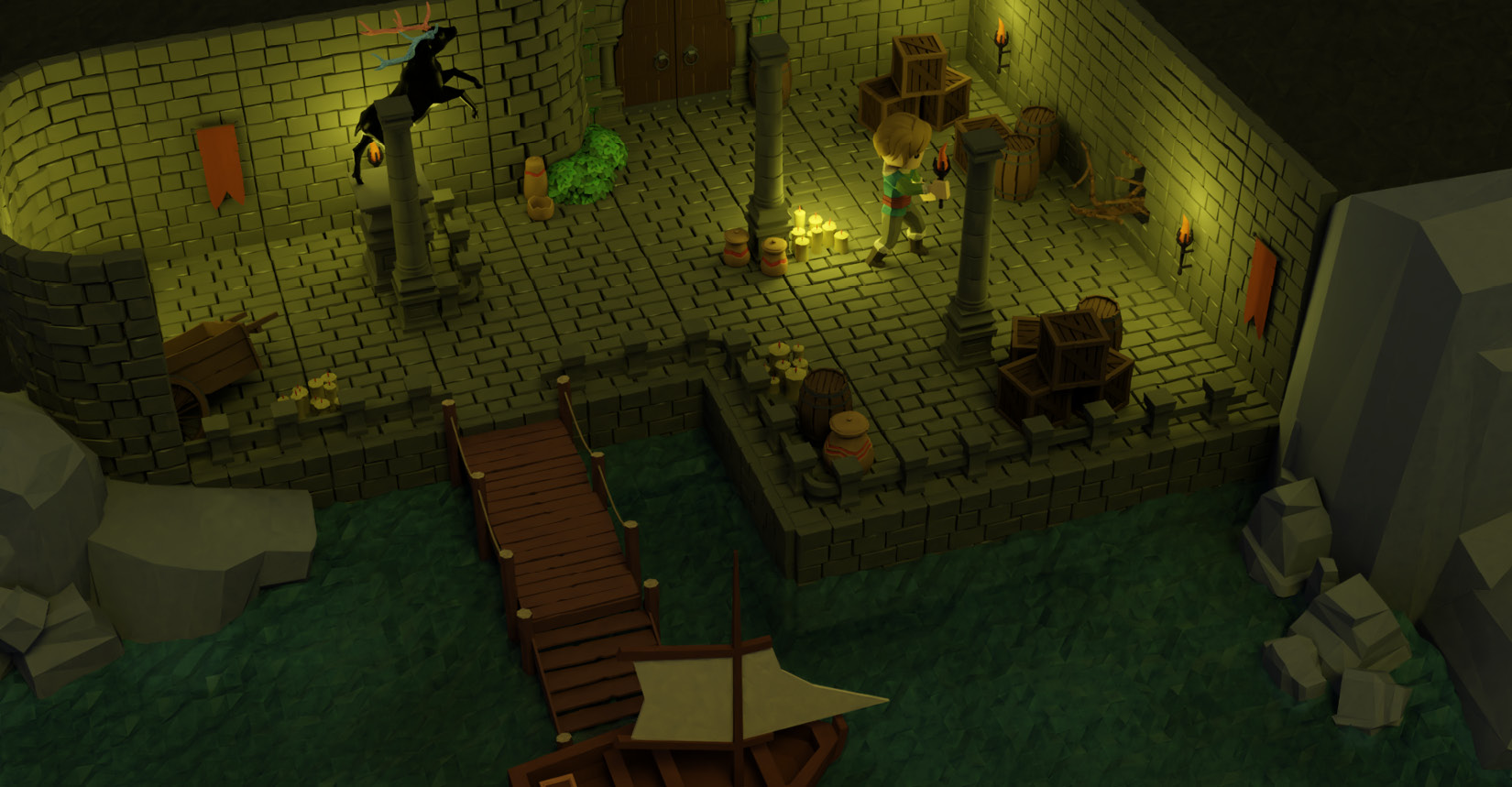
Figure 9.1 – We’ll be building this small level for Clara to discover
Our world will consist of a dock inside a cave that has access to the sea. When Clara anchors her boat, she sees inside the cave. There isn’t much light to begin with, but as little as she can see, the dock leads to a pier with laid stone. She can also see that there are a bunch of boxes, barrels, and pots distributed here and there. Though the sconces on the walls will start unlit when the game runs, as shown in Figure 9.1, you can see that all the sconces on the walls are lit. This is because we want to show you a later stage in the game so that you can see what we are aiming for. Otherwise, it would have been a dark figure.
In Chapter 10, Making Things Look Better with Lights and Shadows, we’ll investigate how we can create a more dramatic-looking level by utilizing appropriate light types and enabling shadows. We covered some of this in the context of Blender in Chapter 4, Adjusting Cameras and Lights, but we’ll do it in the context of Godot as well.
Level design versus game design versus visual design
If you are new to game development, then some of the names you come across might be confusing. The word design is one such example since it usually implies what people see. However, in actuality, it means a fashion, or a formula to do or conceive something. Let’s discuss it in the right context.
We could have designed the level differently so that access to the door at the end of the pier would be challenging. Perhaps the light conditions are so poor that Clara needs some help to see an important clue. To make progress in the game, game design rules will define how the player will interact with the world. Perhaps it’s enough for the player to click game objects in the world, while other times, it’d be better to have an inventory and a crafting system.
Lastly, the visual design has nothing to do with the previous two design concepts. The cave walls could still be cave walls but instead of having a low-poly and stylized look, they might have looked ultra-realistic, where you could feel the stones were damp and covered with moss. Would this have added anything to the game and been fun? So, all these design principles are equally important and yet distinct.
The level, Level-01.blend, is available inside the Blender Models.zip file at the root of this book’s GitHub repository. You’ll most likely need it open so that you can use it as a reference when you are building the level in Godot.
We will start building the level by laying out different sections of it. Speaking of which, we must follow these steps to structure our first level:
- Create a new scene and save it as Level-01.tscn inside the Scenes folder.
- Place a Spatial node as root and rename it Level-01.
- Create more Spatial nodes inside the root node with the following node names:
- Floor
- Columns
- Walls
- Rails
- SunkWalls
- Props
- Rocks
- Sconces
- Dock
We’ll be using these child Spatial nodes to store different parts of the level since we’ll end up having a lot of parts in this level, despite it being very small. The following screenshot shows the node structure after our last effort:
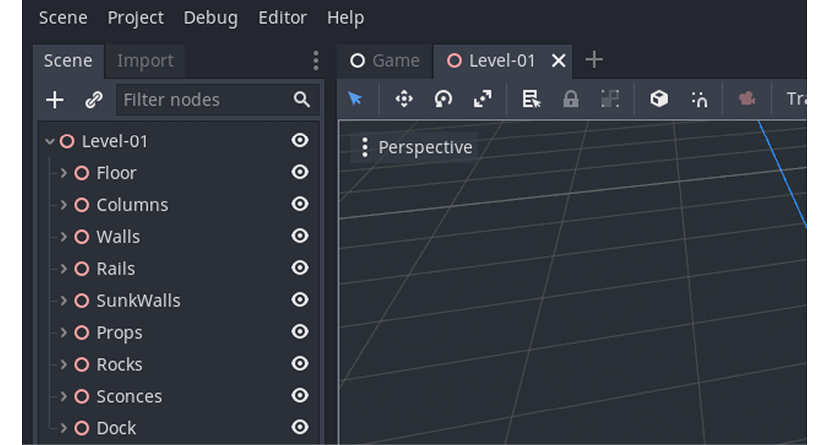
Figure 9.2 – Different structures for the level are grouped under many Spatial nodes
Inside these Spatial nodes, we’ll place the relevant parts of the level. For example, the floor pieces will go inside the Floor node. We can put down our first asset easily by doing the following:
- Highlight the Floor node in the Scene tree.
- Press the chain icon at the top to instance another scene inside your highlighted node. Alternatively, you can press Ctrl + Shift + A.
- Type Floor_Standard in the Search section of the pop-up screen.
- Select Floor_Standard.glb from the Matches section, as shown in the following screenshot.
This will create an instance of Floor_Standard.glb inside the Floor node:
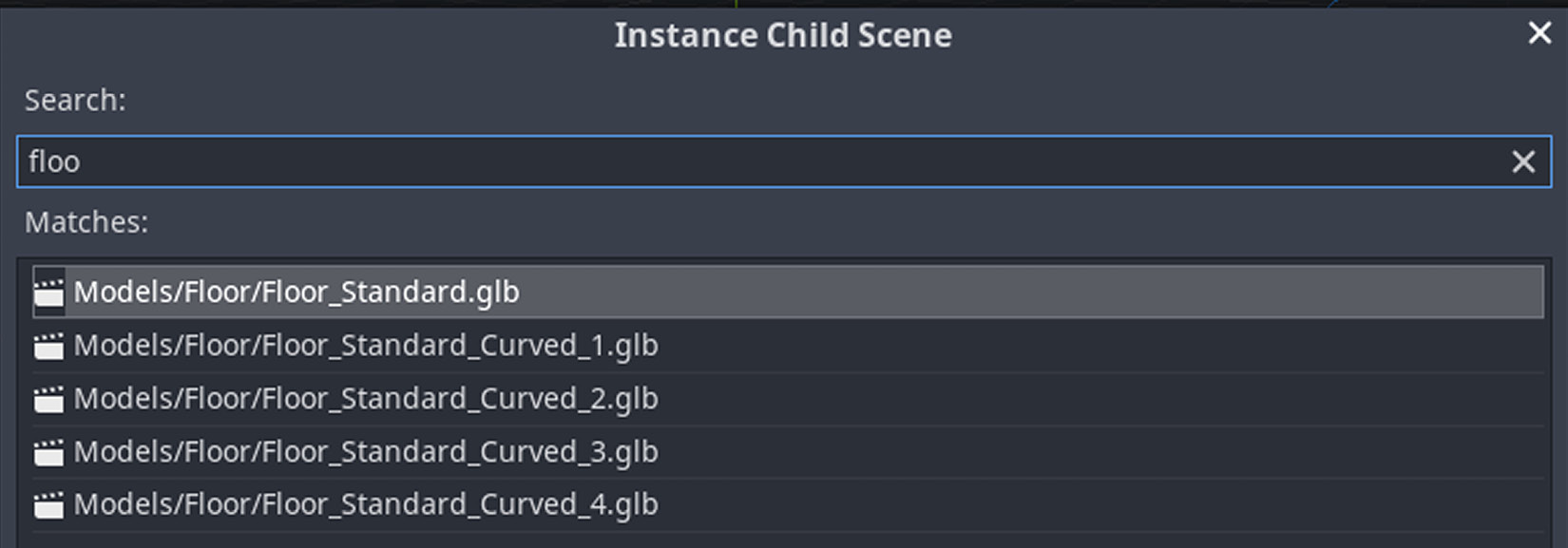
Figure 9.3 – You’ll want to use the search area to filter out the unwanted matches
You may have noticed that although we wanted to inherit a scene that should normally have a .tscn file extension, instead, we instanced a glTF file. In Chapter 7, Importing Blender Assets into Godot, we learned how to create scenes out of glTF files. So, we could have done that and created a Floor_Standard.tscn scene, then instanced that scene inside the Floor node as well. We took a shortcut instead. Creating scenes is useful when you are going to add additional elements besides the model structure itself. We don’t need additional elements for the floor, so it’s alright to instance just its glTF version.
On the other hand, there will come a moment when we create our level when directly instancing glTF files won’t cut it. For example, when we tackle lights and shadows in the next chapter, it will make much more sense to create a scene out of the sconce model and add a light object to the same scene. Hence, the sconce scene will take care of displaying a glTF model as well as holding a light object so that it can programmatically be turned on or off later. If you simply want to display models, but don’t need anything more than that, instancing a glTF file is usually enough.
After you add the first piece, it will be automatically selected. If it’s not, you can click the floor piece in the 3D view or highlight its node in the Scene tree. Once it’s been selected, you’ll see a gizmo at the center of the model that will let you move and rotate the piece around. The directions of your gizmo may look different if you have rotated your view. The following screenshot shows an example of what we expect to see:
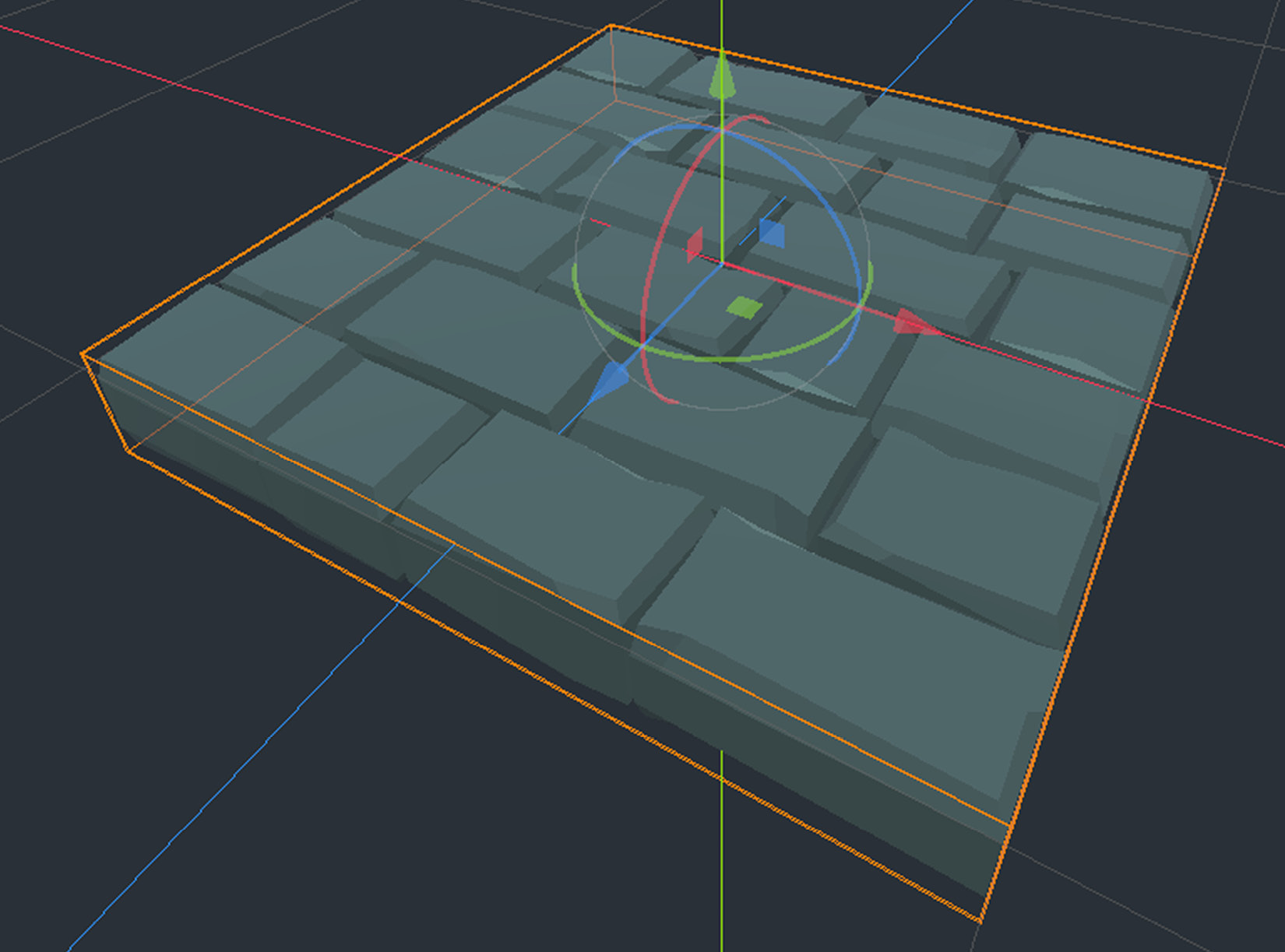
Figure 9.4 – The gizmo for moving and rotating an object
The floor plan we are trying to lay out consists of more standard floor pieces. So, an easy way to get extra pieces is to duplicate the existing pieces and move them aside, as follows:
- Select the Floor_Standard node in the Scene tree.
- Duplicate it by pressing Ctrl + D.
- Move the new floor piece by dragging either the blue or the red axis in the gizmo.
This will add a new floor piece to the scene and move it around. We are intentionally ignoring the green (Y) axis since we don’t want the floor to have any elevation at this point. However, for your games, you can design levels with different height zones and connect them with stairs.
Since our floor plan looks like a grid, it would be nice to have the floor pieces snap to each other. We can do this by moving the pieces in either direction on the XZ plane while limiting their movements to precise increments. To simulate this, delete the most recent floor piece you created, and then do the following:
- Duplicate a new Floor_Standard node.
- Hold down Ctrl and use either the X or Z gizmo arrow to move the piece two units.
Why did we move it by two units? Because the model is designed to fit in a grid that’s 2 x 2 meters in size. You can open the relevant Blender file to observe the dimensions. We are not measuring things in Godot but it’s still respecting the scale and unit aspects set in Blender. That’s why we made sure the scale for the model was set to 1. If you need a reminder on this, we suggest that you read the Applying rotation and scale section in Chapter 6, Exporting Blender Assets.
After implementing the latest instructions for moving pieces with the snap feature on, you’ll get the following output:
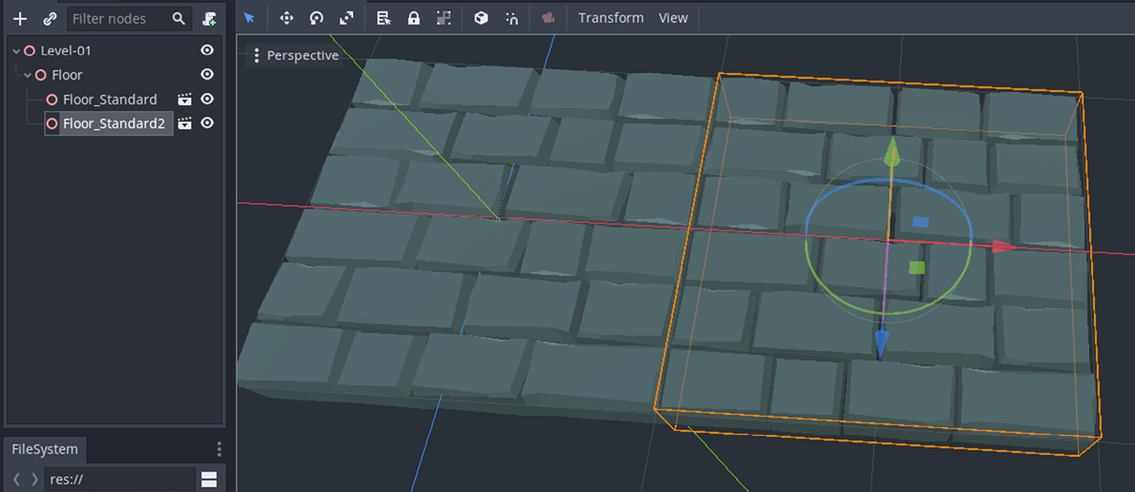
Figure 9.5 – The new floor piece is right next to the old one
All there is left to do at this point is duplicate enough floor pieces and move them around by using the snap feature. Also, you’ll need to instance and place two new models inside the Floor node:
- Floor_Standard_Curved_1.glb
- Floor_Standard_Curved_4.glb
These curved floor tiles will accommodate curved walls, which means we can keep the architecture consistent. By duplicating enough floor tiles and adding the new curved pieces, and after moving the pieces around, we’ll achieve the following output:
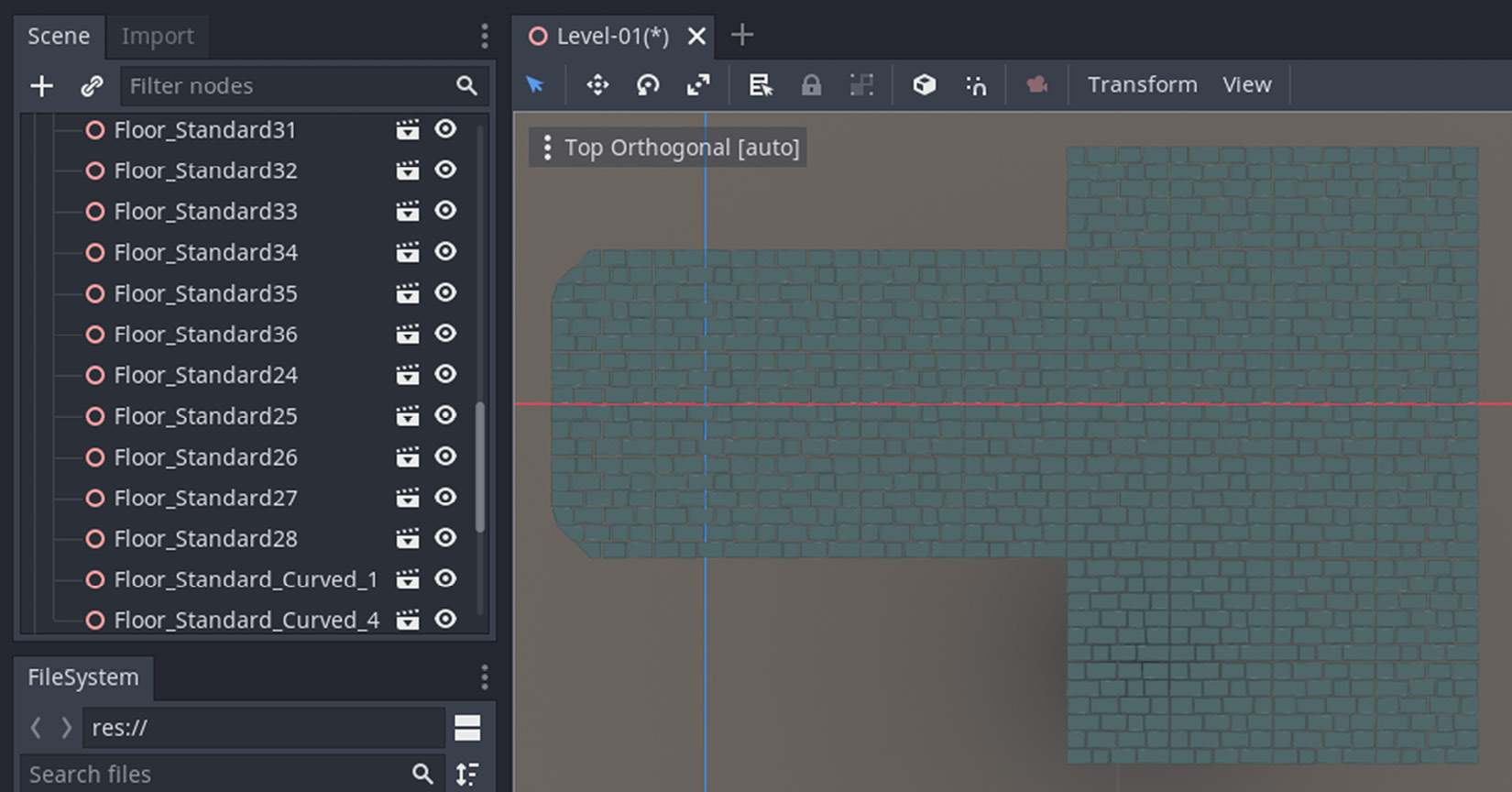
Figure 9.6 – With the two newly added types, the floor is ready
All the floor pieces are now under the Floor node in the scene, and this effort completes our task of constructing the floor. We’ll follow a similar approach to lay the other parts of the cave under separate Spatial nodes.
Erecting the walls
The next order of business in constructing the level is putting up the wall sections. You can do so by instancing wall pieces under the Walls node, similar to the way you did for the floor pieces. As a substitute for providing you with very similar instructions, we’ll use this section to highlight a few special cases you may come across.
For example, you’ll eventually want to place wall pieces that will connect at a corner. So, you need to rotate one of the pieces around its Y axis by 90 degrees. You can do this either by using the gizmo or by typing the exact value in the Inspector panel under Rotation Degrees in the Transform section.
Another situation is with the wall that has a hole in it, which lets a bunch of twigs creep into the dock area. This is a detail you can see on the right-hand side of Figure 9.1. We suggest using Wall_Hole.glb for that particular section of the level. Similarly, Curve.glb should be placed over the curved floor pieces we have already established.
Although a door is technically not a wall, we could assume the arch and the door can get along with the other wall pieces. After all, they conceptually belong to the same structure. So, for that section, you can utilize the following pieces:
- Wall_ArchRound_Overgrown.glb
- Arch_Round.glb
- Doors_RoundArch.glb
Lastly, when you lay out all your wall pieces, you can duplicate them and pull them up two units on the Y axis. This will make the walls the same height as the arch and the door. Once you’ve done this, your floor should resemble what you can see in the following screenshot:
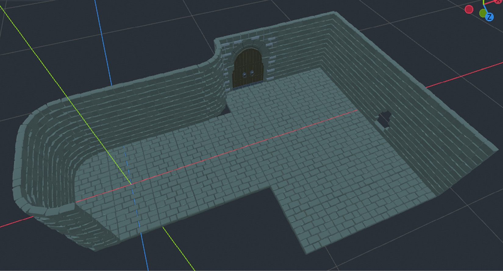
Figure 9.7 – The level is starting to look more like our reference picture
As you may have noticed there is a gap on the floor by the curved wall piece near the door. We’ll fill that gap by cleverly placing two green plants soon. Otherwise, you’d have to prepare a floor piece for edge cases like that. Either way is fine and going back and forth between Blender and Godot to complete missing pieces is also part of the process.
Since we’ve been handling the walls, we can extend this effort by using additional wall pieces to simulate the section of the level that meets the seawater in the cave.
Sinking the walls
It seems the architect of this place went to great lengths to have stone bricks laid out to prevent mother nature from tarnishing what’s under the floor. Smart!
To accomplish what the architect had in mind, you can utilize the standard wall pieces to create a curtain-like structure right where the floor is connecting with the water. In the end, when you place these pieces inside SunkWalls in your Scene tree, you’ll be looking at what’s shown in the following screenshot:
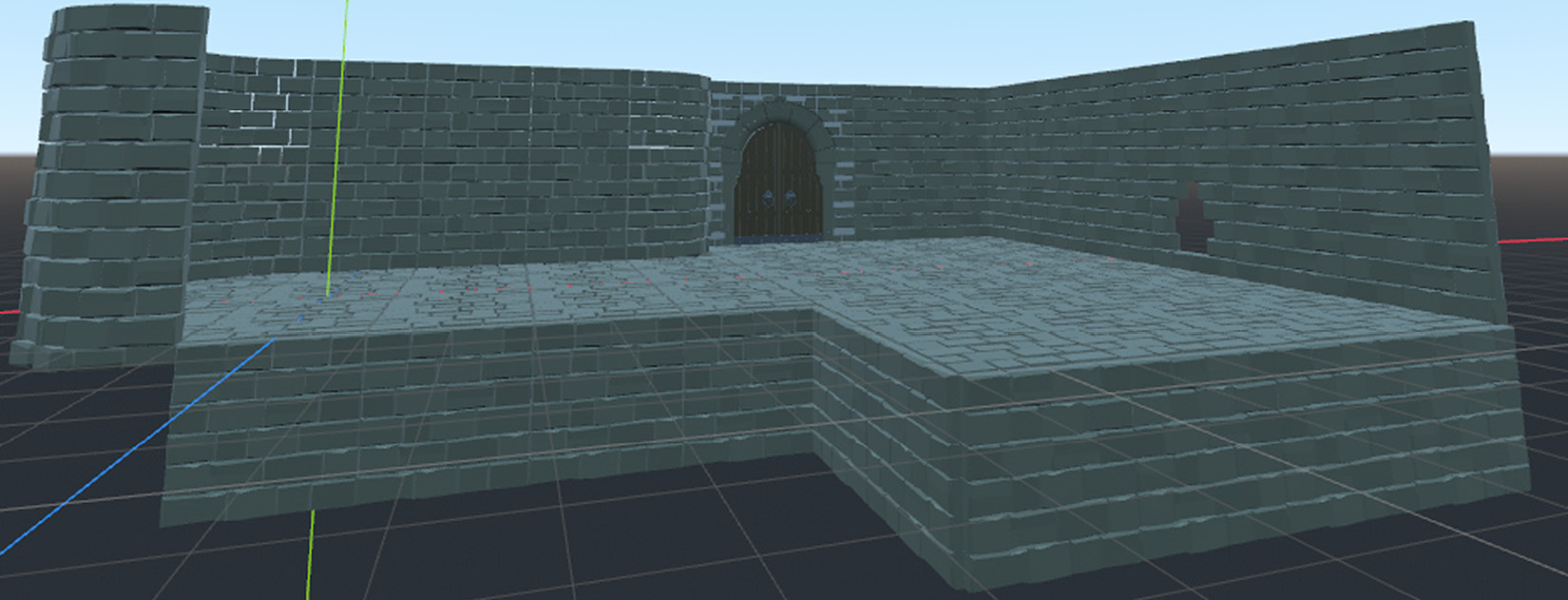
Figure 9.8 – The same wall pieces are used to prevent water from leaking under
The ebb and flow of the sea will now be kept at bay. Notice that we didn’t want the sunken wall parts to go all the way around the floor. This is because you can always limit the camera angles to not show the back parts of the structure. It’s a cheap way to keep the asset count low. However, if you want to give full freedom to the player so that they can rotate around the whole structure, you may want to change your level design to accommodate that. We’ll be investigating camera settings in Chapter 12, Interacting with the World Through Camera and Character Controllers. For now, we still need to finish our level.
Placing the rocks
Since we are currently concerned about the parts near the water, let’s add some rocks to the scene. In the Blender file for this level (Level-01.blend), you’ll see individual rocks. They have been organized to give the illusion of a rock formation. It’s perfectly fine to follow a similar approach and place specific rocks into your scene in Godot too, more specifically under the Rocks node.
However, there is an easier way. What if you exported the left and right rock formations as a single object from Blender? This is entirely possible, and that’s why we have prepared two files for you:
- RocksLeft.glb
- RocksRight.glb
You can instance these two files and move the instances freely using the gizmo. This means you don’t have to use the snap feature. Adjust the position of the rocks wherever you think is best.
Speaking of moving assets without using the snap feature, perhaps we can practice it a bit more. Since the floor looks empty, it’s time we discuss complementary design elements such as props.
Distributing props
A prop is an object that serves as a support element. Props are also often called necessary clutter since they complete a décor. Otherwise, when things look too sterile, it’s less pleasant to the eye and we start paying attention to repeating patterns or unnecessary details.
Instead, we want the person who’s experiencing the scene to feel at ease. This is also a great way for designers to hide important elements in plain sight. To that end, we will use the following list of props and distribute these assets around the scene:
- Barrel.glb
- Backpack.glb
- Bush_Round.glb
- Candles_1.glb and Candles_2.glb
- Cart.glb
- Crate.glb
- DeadTree_3.glb
- Flag_Wall.glb
- Pot1.glb, Pot2.glb, Pot3.glb, and their broken versions
- Statue_Stag.glb
Once you’ve finished moving the props, your scene will look as follows:
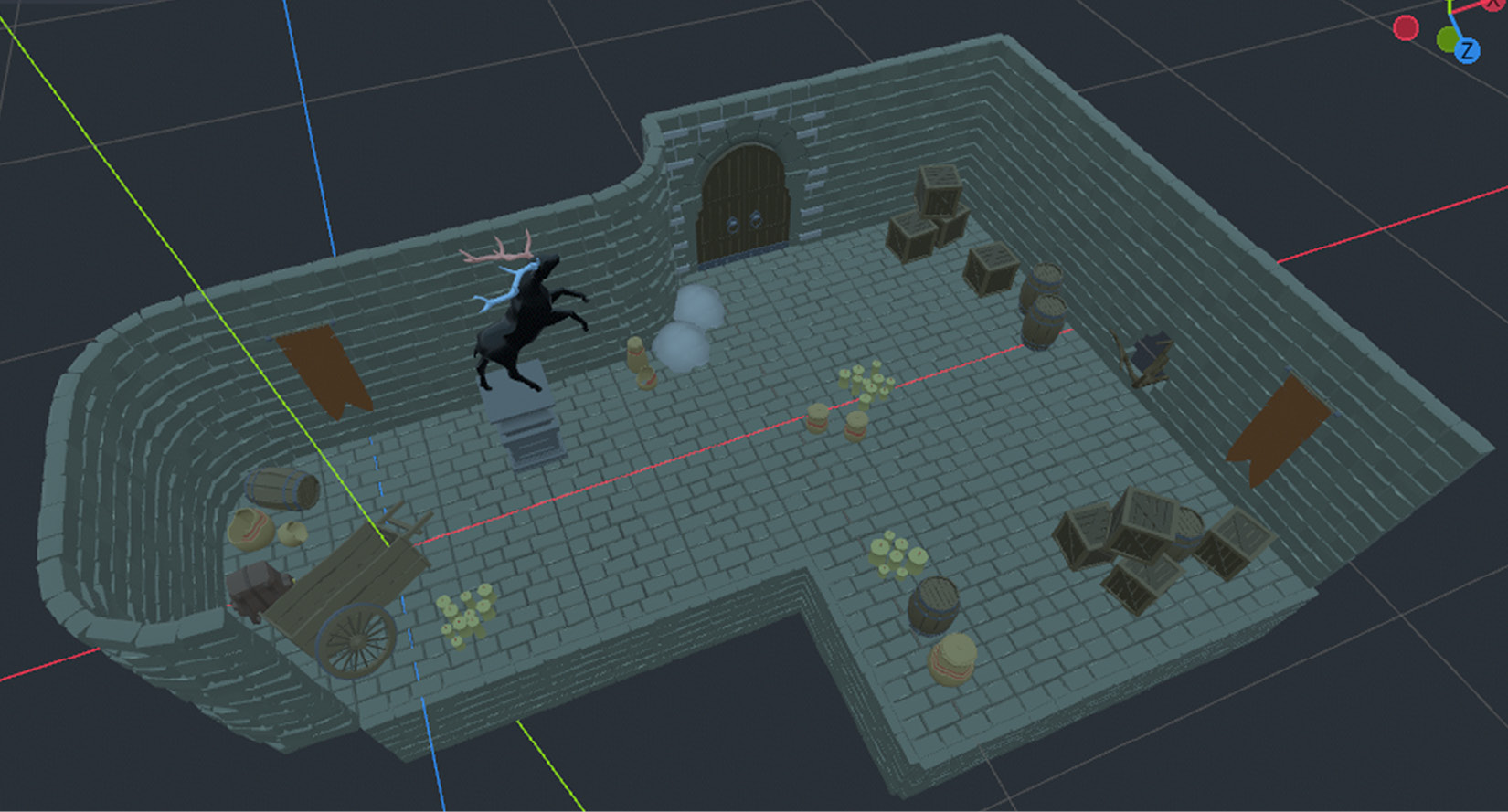
Figure 9.9 – The props have been distributed all over the dock
While you are at it, you may as well instance Column_Round.glb, make two more copies, and place them under the Columns node. Also, Rail_Corner.glb and Rail_Straight.glb could be placed along the edge and near the stag statue. You don’t have to be pixel-perfect with these objects, but if you want to be precise, you can use Level-01.blend for reference.
Finishing the rest of the level
To finish off the level, we need to place the sconces and construct a pier. These assets are no different than the other ones you have instanced and moved around the level.
However, placing the dock pieces may throw you off a bit as far as positioning goes. You may find that the stairs piece looks slightly off dimension-wise. Sometimes, assets are designed to be generic, while other times, assets will be designed so that they can fit or connect with the other models seamlessly. Regardless, since it’s possible to adjust the final position in Godot, we can recover from these minor issues.
To simulate how we dealt with this issue, we’ll give you the Translation values we used for the positions of both pieces:
- Dock_Long: 4, -1, 5.5
- Dock_Stairs: 4, -1.5, 8.9
Your values will most likely be different since you were undoubtedly moving your level pieces in directions that felt natural to you. If your numbers don’t match our example, don’t worry. We would like to point out the relative difference between the two structures. You’ll also most likely have one number that’s the same in one of the axes, either X or Z. Also, an educated guess on our end, your Y for the stairs will be 0.5 lower. This should result in a pier structure that looks like it was designed as one piece. If you want to have a taller pier, then you can create a copy of the stairs and move it accordingly. That’s the benefit of having separate pieces.
We suggest that you add the boat model under the Docks node in the Scene tree at this point since it could be considered as part of the docks area. This concludes the construction of our level. It should look as follows:
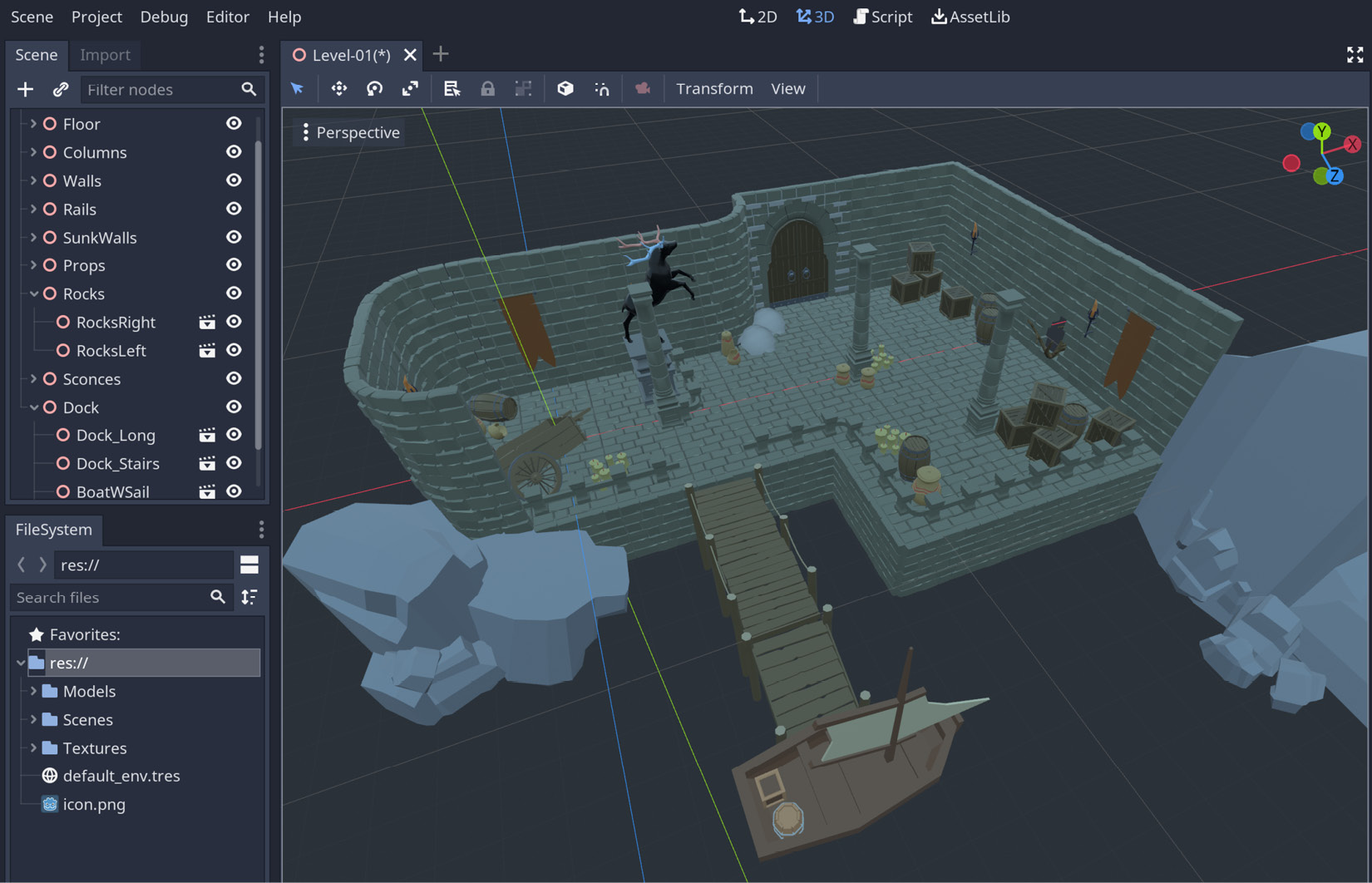
Figure 9.10 – The level has been reconstructed in Godot
Despite our claim that the level’s construction is finished, you may have noticed that there are a few odd looking things. We have a dock area with no water – and what are those ugly round things doing by the door? We’ll find out how we can remedy all this in the next section.
Constructing the missing materials
When we were placing the props, we covered the gap near the door by placing a bush prop (this can be seen in Figure 9.10). However, there is something awkward about those bushes. Similarly, the arch over the door has some weird-looking dangling things over the stone bricks. They should be showing greenery and leaves but all we have is a bland, gray surface. We’ll fix these issues in this section.
In addition, while it made sense to export individual models from Blender and place them in a Godot scene, it didn’t make sense to export the water body. Even in Blender, that object was a plane that has been applied a shader that mimicked water. We’ll recreate that effect in Godot.
Fixing the leaves
First, let’s describe what the problem is with the gray leaves. All the other models seem to have their materials displayed properly. Despite all intentions and efforts, certain things are never fully transferred between applications. This is the case with the leaves. We need to get a bit technical for a more thorough answer though.
How would you go about designing a leaf in 3D? Since a leaf has so many details around its edges, it’s hard to display that much detail without using enough vertices. To be conservative, you can use an object with the least number of vertices and apply a transparent leaf texture to this basic object. The following screenshot shows an application of this method:
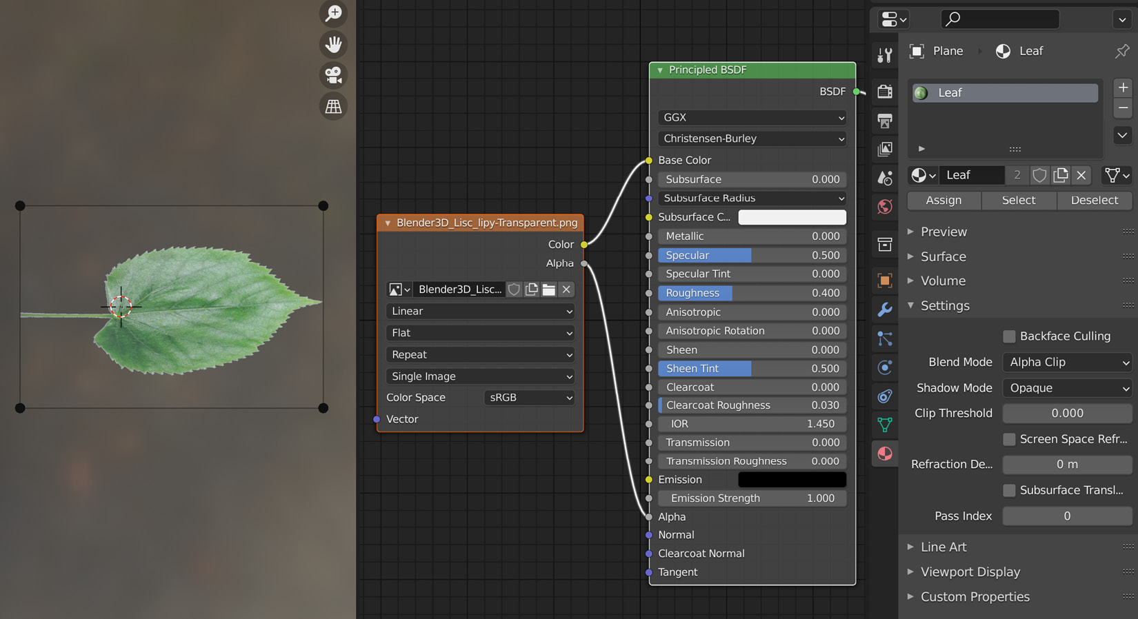
Figure 9.11 – A transparent file is used as a texture for a rectangle shape
The preceding screenshot shows a very simple shader. The alpha value of the texture is attached to the Alpha socket of the shader. Also, Blend Mode under Settings for the material is set to Alpha Clip. This means that the alpha parts of the texture will be clipped out of the result. We need to do the equivalent of this in Godot.
Unfortunately, Godot doesn’t automatically understand and turn on transparency for imported materials. We’ll have to do some manual work to display the leaves correctly. Luckily, this is also going to get you familiarized with the materials and their settings in the Inspector panel.
Let’s start by finding the material for the bushes. The Models folder is structured in a way to keep distinct models inside individual folders. Hence, expand the Bush folder in FileSystem panel and double-click the Texture_Leaves.material item. This will populate the Inspector panel with this material’s properties. There is a lot to look at, but we only need to tweak a few things:
- Expand the Flags section.
- Turn the Transparent setting on.
- Expand the Albedo section.
- Drag and drop Leaf_Texture.png from the Textures folder into the Texture field. As an alternative, you can click the Texture field and Load the necessary file.
As you may have noticed, the texture for the material was missing, so there was no chance for the bushes to display anything. Second of all, by turning the transparency on in the flags, we are asking Godot to respect the transparent parts of the texture file. You can switch it on and off to see the difference if you like. In the end, our scene will look as follows:
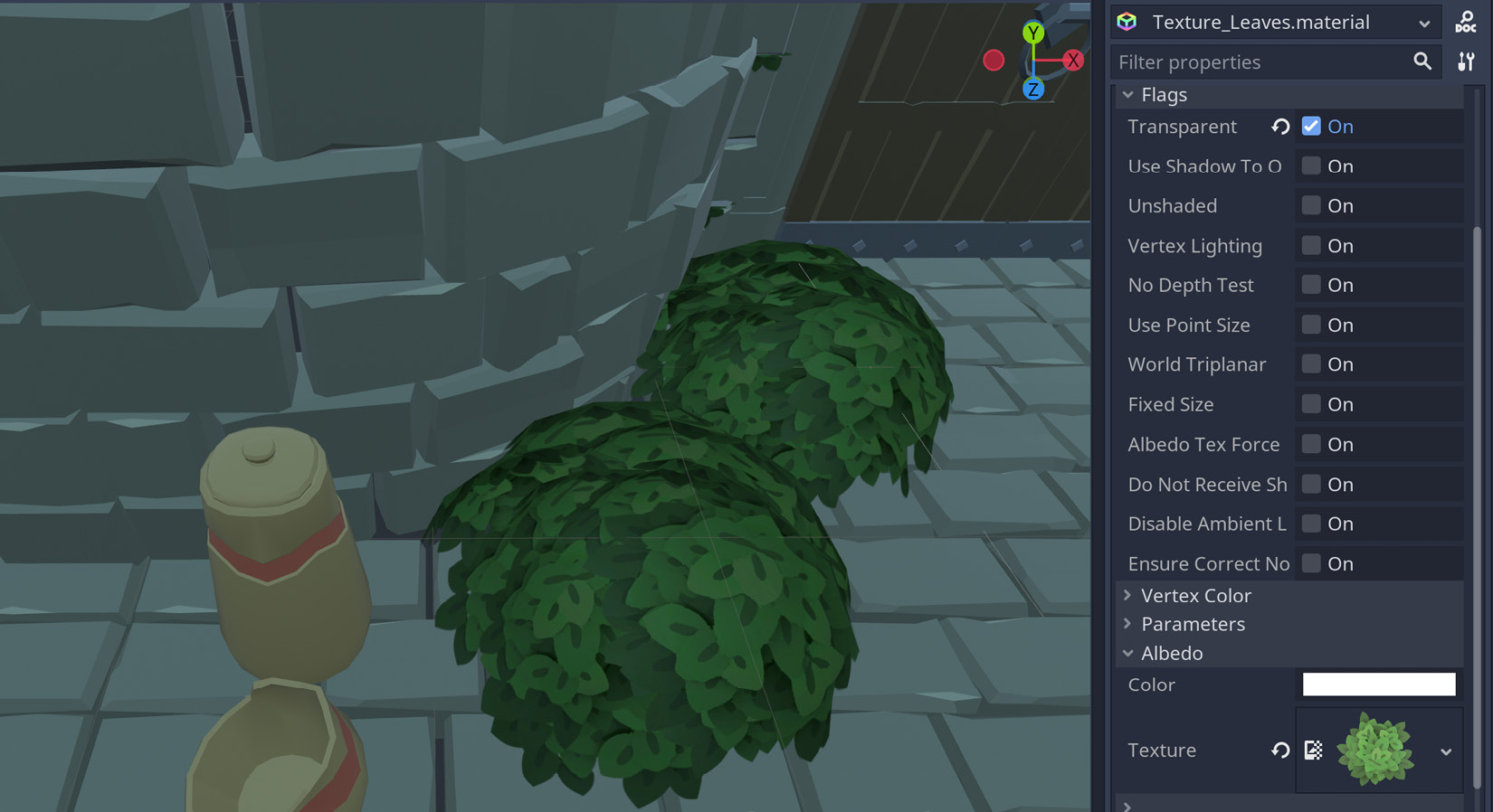
Figure 9.12 – Our bushes are starting to look healthier again
You can do the same thing for the arch model, which can be found in the Architecture folder inside the Models folder. This may look like you are repeating yourself, and you are right about this. Since we are keeping separate models that use the same Blender material inside their relevant folders, the materials are duplicated as well. A detailed discussion about this was provided in the Deciding what to do with materials section of Chapter 7, Importing Blender Assets into Godot. Since this is an organizational issue, we leave the decision to you, but you now know how to enable transparency in materials.
Another missing piece in our material puzzle is the water object. We intentionally omitted the export for that area. To most game developers out there, writing shader code is entering dangerous waters. Nevertheless, that’s exactly what we’ll do. Hopefully, you’ll see that there is nothing to fear.
Creating the water
How do you model a body of water? The answer is not simple, and it even is a bit philosophical. The following is a homage to Bruce Lee’s famous philosophical quote on martial arts, which uses water as an analogy:
It’s hard to imagine what vertices we should create and organize for water in Blender or Godot. Instead, we give qualities of water such as reflection, refraction, undulation, and murkiness to simple objects, such as a plane or a cube.
Thus, for this effort, we usually rely on shaders instead of a 3D model. In this section, we are going to write a very simple water shader. In the end, you can either use the shader from our example or find another example on the internet. After all, there are a lot of examples out there, since creating a decent water shader usually depends on your use case, and one solution sometimes doesn’t fit all.
Let’s start by creating a water object:
- Place a MeshInstance node under the Dock node and rename it Water.
- For this new object, assign a PlaneMesh to its Mesh property in the Inspector panel.
- Click this PlaneMesh to expand its properties, and fill in the following values:
- 20 for both x and y in Size.
- 20 for both Subdivide Width and Subdivide Height.
We’ll explain what these numbers mean soon, but here is what your Inspector panel should look like:
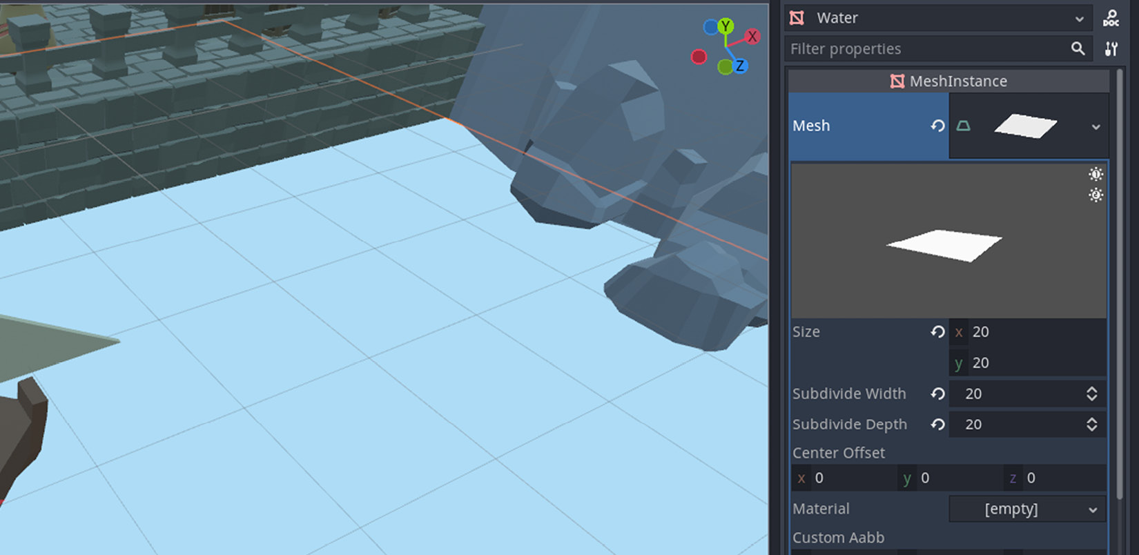
Figure 9.13 – A rather gray-looking body of water so far
The preceding screenshot shows the properties of a PlaneMesh in the Inspector panel. We have chosen a size that made sense as far as the level’s dimensions are concerned. Using the gizmo, as you did for moving other objects, position the water object where it makes sense concerning the dock area and the overall scene. Once we have written our shader to make this gray object look like water, you may also want to adjust its Y position too.
Additionally, perhaps coincidentally, we chose 20 as the subdivision value. You can divide the plane into finer pieces if you want, but a value such as 20 will introduce enough vertices. So, yes, you have effectively created vertices in Godot as opposed to doing so in Blender.
We are now ready to change the look of this gray plane. For this, we’ll create a material for it:
- Right-click the res:// item in FileSystem and choose New Folder.
- Type Materials and confirm.
- Right-click the Materials folder in FileSystem and choose New Resource.
- Search for ShaderMaterial and confirm.
- Save it as Water.tres in the upcoming Save Resource As screen.
Normally, a newly created item will be displayed in the Inspector panel, but if it doesn’t or if you brought another object’s properties to the Inspector panel, find Water.tres in FileSystem and double-click it. You’ll see a barebones material with a white sphere as a preview in the Inspector panel. It needs a shader to get more water-like visual qualities. This is how you can create it:
- Right-click the Materials folder in FileSystem and choose New Resource.
- Search for Shader and confirm.
- Save it as cave-water.tres in the upcoming Save Resource As screen.
In Chapter 2, Building Materials and Shaders, we discussed the relationship between shaders and materials, and how they go hand in hand. That was done in Blender, but the concept is universal. Hence, we’ve created a material and a shader in Godot. Now, we must associate the two:
- Bring up the Water.tres file’s properties to the Inspector panel.
- Drag and drop cave-water.tres into the Shader property in the Inspector panel.
The water material has now been assigned an empty shader. We’ll explain the shader code after you complete the following steps:
- Double-click cave-water.tres in FileSystem.
- Type the following code in the newly expanded Shader panel:
shader_type spatial;
uniform sampler2D wave_pattern;
uniform vec4 color:hint_color = vec4(0.19, 0.71, 0.82, 0.44);
uniform float height_factor:hint_range(0,1.0) = 0.1;
void vertex(){
vec4 wave = texture(wave_pattern, UV);
float displacement = sin(VERTEX.x * wave.x * TIME)
+ cos(VERTEX.z * wave.z * TIME);
VERTEX.y += displacement * height_factor;
}
void fragment(){
ALBEDO = color.rgb;
ALPHA = color.a;
}
The shader code we have written exposes a few options to the Inspector panel, starting with the lines that start with the uniform statement. This is so that you can modify the material’s properties, just like you were able to change the settings of the leaf material earlier in the Fixing the leaves section. That one was a very elaborate shader with lots of options. Ours is a very simple shader with only three parameters:
- A wave pattern for creating randomness
- A color for the water (by default, this is a light blue color)
- A height factor to control the motion of the waves (by default, this is 0.1)
Two of the properties have their default values. We’ll show you what you can pick for the wave pattern later in this section, but first, let’s explain the general idea behind all this since this might be the first time you are writing shader code.
Built-in Godot shader functions
The two functions, vertex and fragment, are built-in shader functions. The former controls what each vertex will do, while the latter takes care of how the overall object will look. Godot has more default functions; we’ve provided a link in the Further reading section for you to discover.
Since the fragment function looks simple enough, we’ll cover that one first. One of the properties we exposed, color, will be used in this function so that we can paint the object with the color we want. Consequently, we are taking the red, green, and blue channels of the input color and applying them to the ALBEDO property of the shader. Albedo is a scientific term for color. In some applications, it’s also referred to as Diffuse or Base Color, such as in Blender.
Naturally, we would like to have some translucent qualities for our water object. For that, we are using the input color’s alpha channel and binding it to the ALPHA property of the shader. It’s a simple but effective way to create transparency. Speaking of which, if you comment out the vertex function, you should still be able to see the transparency because each function is responsible for one major aspect. However, they complement each other when used together. So, it’s now the vertex function’s turn.
It would be nice to have the body of water move up and down a bit. That’s the reason why we have introduced more vertices to the plane mesh by subdividing it. The vertex function will take each vertex and change its y value to create an up and down motion. The last line in the function is responsible for that. How much should each vertex change though? Well, that depends on your use case. However, we came up with a displacement value that seemed appropriate and yet exciting enough to simulate a somewhat calm water feature in this cave.
While calculating displacement, we are using a texture and sampling some of its values. It’ll bring randomness to the way the vertices will move. To that end, we are combining the x and z values of each vertex with the x and z values of the incoming texture (wave). You could alter a combination of some of those properties and still get a similar result. Perhaps what’s more important is the use of the built-in TIME property, which is telling the GPU to change the result with each millisecond passed. Remove TIME from the equation and everything will be displaced once and sit still.
Finally, we regulate the intensity of the displacement with a height factor that can be adjusted in the material settings. This concludes our water shader. The shader and material have already been connected, but we have yet to tell the Water node which material it should use. To do so, follow these steps:
- Select the Water node in the Scene tree.
- Expand the Material section in the Inspector panel. You’ll see a slot with a label of 0.
- Drag Water.tres from FileSystem to the 0 slot.
Voila! The dock should now have a water object that’s modulating over time. Move and zoom your viewport camera in to get closer to the sunk walls to notice the alpha effect too. This is looking nice already, but we can take this a step further by applying the shader a noise texture, which will add more variation to the way the vertices fluctuate:
- Expand the Shader Param section in the material’s settings in the Inspector panel.
- Attach a New NoiseTexture for the Wave Pattern property.
- Expand this new texture and attach a New OpenSimplexNoise to its Noise property.
This will add more randomness to the way the vertices are displaced. When you are done with all the code bits and tweakings, your Inspector panel should look as follows:
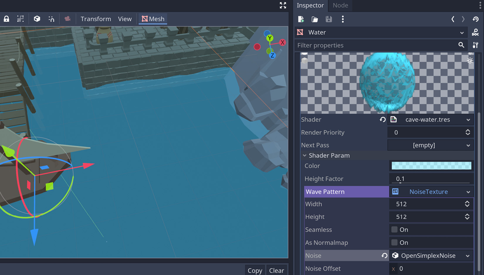
Figure 9.14 – Notice how the water is transparent and wavy along the sunk walls
It’s possible to fuss with the values of the noise to create more drastic effects, but we leave that to you. By controlling the height factor and color, you can simulate calmer or stormier water conditions as well. With that, you have created an important missing feature.
About keeping the shader separate
While creating the water material, you could have used an in-memory shader for the material using the dropdown in the Inspector panel. Most Godot features usually start and stay this way, but we followed a different approach by creating a resource first and then assigning it later. Thanks to this method, you can create different water shaders and swap them as you need them.
With that, we have taken care of placing all the necessary elements and even completing missing parts, such as fixing and/or creating new materials. However, while creating the layout, did it feel like you were duplicating and moving so many of the same assets, especially with the wall and floor pieces? We bet it did! So, let’s present a very helpful Godot tool with which you can lay things out easily if your layout is grid-based.
Laying models on a grid
The main difference between placing objects such as candles, pots, and barrels, short props, and floor and wall pieces is that you can distribute the former objects willy-nilly. They don’t have to follow a pattern, whereas the floor and wall pieces must snap to each other. This kind of structure is also referred to as a grid.
To speed things up, we even chose to duplicate an existing piece instead of instancing a fresh one because when you create a new instance, it’d start at the scene origin, and you’d have to move this new piece near your current area. You can even select multiple tiles in a row, duplicate them, and snap these next to the old batch. Despite all these shortcuts, since all this sounds formulaic, perhaps there should be a better tool. GridMap to the rescue!
If you have used Godot for 2D, you may already be familiar with the TileMap node. GridMap is the same except it works in 3D. Thus, whereas TileMap will let you add sprites to your scene, GridMap will use meshes. For those of you who have never used a TileMap node, both of these mechanisms in Godot are responsible for using a set of tiles or meshes.
Benefits over manual placement
The GridMap solution we are offering is not just for you to expedite the creation of your levels. Since the pieces are repeating, the GPU will optimize the rendering of said pieces and you’ll get higher frame rates. This is usually a very sought-after result among game developers, particularly when your levels grow and the number of objects you use in a scene starts to matter.
In this section, we’ll present the general settings of a GridMap node. Although this node depends on MeshLibrary to do its job, it makes sense to understand the individual settings at this point than mixing both. We’ll learn how to create and utilize MeshLibrary in the Taking advantage of MeshLibrary section.
To conserve and compare what we have done so far, we’ll take things a bit slowly:
- Save Level-01.tscn as Level-01-Gridmap.tscn. The root node could still stay as Level-01.
- Add a GridMap node and rename it FloorGridMap. You can drag this new node and make it the first child right above the Floor node if you wish.
- Turn off the Floor node by pressing the eye icon.
The last set of actions will introduce a GridMap node to the scene. It’s empty for now but we’ll fill it with the floor pieces when we get to know mesh libraries. Your scene will look as follows:
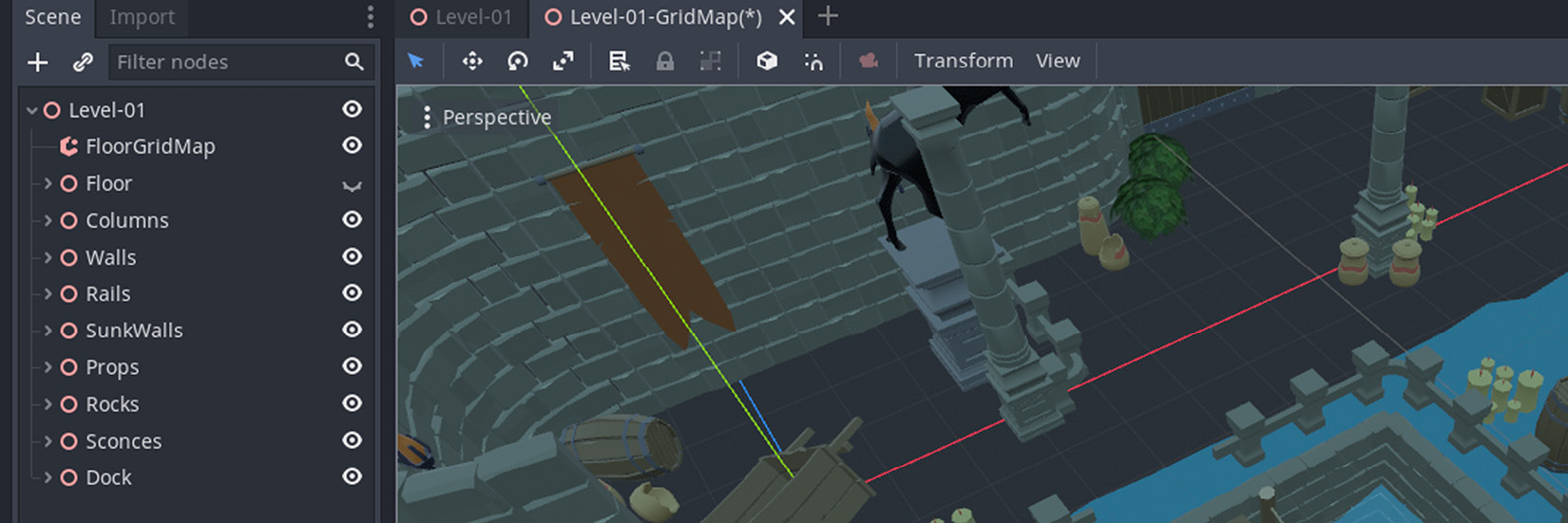
Figure 9.15 – The missing floor pieces will soon be introduced with GridMap
Although we’re missing a mesh library, we have a GridMap node for which we can look at properties in the Inspector panel. We suggest that you select FloorGridMap now and read along. The information we’ll present here will lay the foundation for you to choose the settings of the future grids you’ll use.
GridMap works with a cell concept. A cell is a volume in which one of the meshes will fit. If you expand the Cell section in the Inspector panel for the FloorGridMap node, you’ll see that we have a value of 2 across the board for a cell. Fortunately, our floor pieces are 2 x 2 x 2 meters as well. So, we don’t need to change those values in our case. In your future projects, you may have to match these values to your models’ dimensions.
We’ll ignore the Octant Size setting in our efforts since it’s for more advanced cases where you can further increase optimization. What’s much more important perhaps is the three on/off switches for centering the meshes inside a cell on either axis. We’ll make use of this very soon, but the following screenshot should help you see what we have been discussing so far:
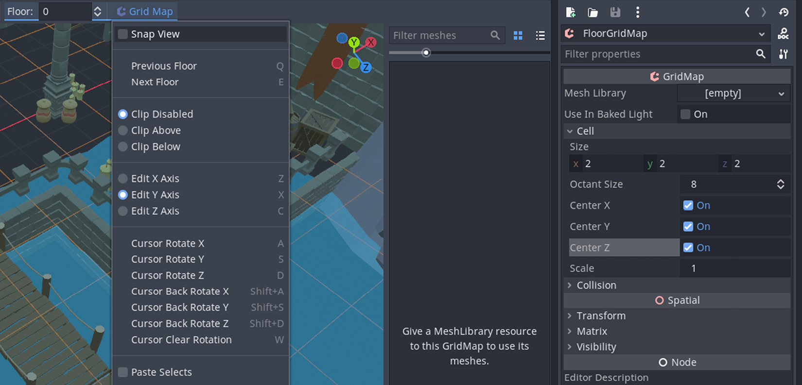
Figure 9.16 – Each GridMap can have settings to define the dimension of the pieces it’ll use
The preceding screenshot also shows an expanded menu and its options when you click the Grid Map button at the top of the viewport. Out of those options, Cursor Rotate Y with the S shortcut will probably be the one you’ll use the most. The floor pieces we laid out earlier in the Creating the cave section all follow the same direction. We tried to cover the floor with props to break the sameness but rotating a floor piece 180 degrees around the Y axis would be another solution.
Now that the theoretical knowledge has been established, let’s move on to practical applications of using GridMap. In the next section, we’ll create a mesh library that we’ll use in tandem with our FloorGridMap to fill in the missing floor pieces.
Taking advantage of MeshLibrary
When you clicked FloorGridMap to investigate its properties, the Godot interface changed slightly, and it informed you that you should assign a MeshLibrary since, without one, a GridMap is ineffective. In this section, we’ll show you what goes into creating a MeshLibrary. We’ll also talk about possible challenges you might face, not technically, but workflow-wise.
There are two ways to create a MeshLibrary. We’ll show you the most common way since the other method involves keeping meshes separately in the filesystem, and our project has not been set up to accommodate that scenario. Without further ado, this is how you create a mesh library:
- Start a new scene and save it as Floor-MeshLibrary.tscn in Miscellaneous.
- Choose a Spatial node as its root.
- Instance Floor_Standard under the Spatial node in the Scene panel.
- Click the Scene button in Godot’s top menu.
- Expand Convert To and choose MeshLibrary.
- Save your mesh library as Floor-MeshLibrary.tres in Miscellaneous.
If you drag and drop the floor piece directly into the viewport, it will be placed somewhere in the scene while considering the perspective of where your mouse cursor was. The floor may, for example, look tiny because it will be far away from you. Zeroing the position should put the object in the center of the world and bring it closer. If you dropped the piece into the Scene tree instead, you won’t have this problem.
The following screenshot shows the state right before Godot converts your scene into a mesh library:
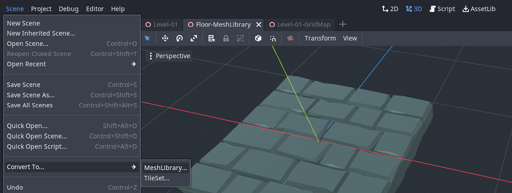
Figure 9.17 – We are converting a scene into a mesh library
Now that we have a floor piece in the library, we can add one more model to it. The goal here is to pile up items that have similar dimensions. This may sound confusing, but let’s add the curved wall. Why? Because although a wall is normally thinner and taller, if you think of the volume the curved wall occupies, it’s no different than a floor piece. Its base is of similar dimensions.
So, assuming Floor-MeshLibrary.tscn is still open, here is how you can introduce another model to the same library:
- Find the Curve.glb wall piece in FileSystem.
- Drag and drop it over Spatial.
- Convert your scene into a MeshLibrary again and overwrite the existing file in Miscellaneous.
This operation will add the newly introduced piece alongside the old floor piece and update the mesh library. Thus, an easy way to create a mesh library is to start a new scene, add as many models as you want, and turn this scene full of models into a mesh library.
We haven’t concerned ourselves with where the pieces will go yet. We’ve just been selecting separate pieces as candidates to decorate a grid. Now, let’s associate the mesh library with FloorGridMap and start laying some models.
Using a mesh library with a grid map
So far, we have been preparing a mesh library to be used by FloorGridMap. We have two pieces inside this library. We’ll use the floor piece first, and then see if it makes sense to use the curved piece.
For a GridMap to work, you need to fill its Mesh Library property in the Inspector panel. Let’s take care of this first:
- Select FloorGridMap in the Scene tree.
- Drag and drop Floor-MeshLibrary.tres from Miscellaneous into the relevant field in the Inspector panel.
This will display all the available models as thumbnails in the reserved GridMap interface, as shown here:
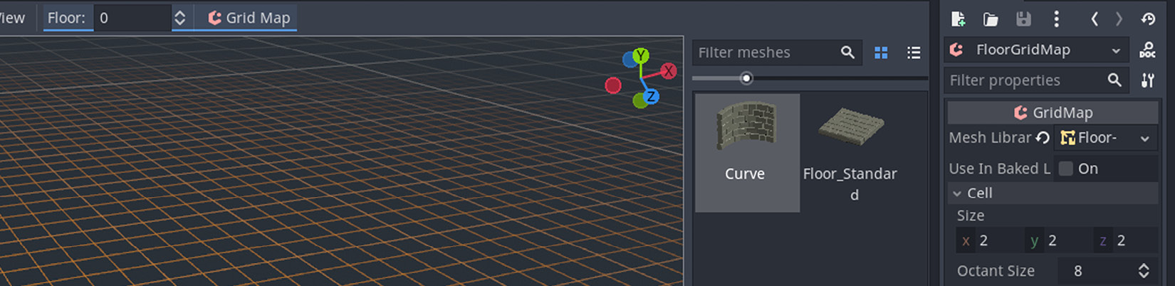
Figure 9.18 – The mesh library can now be used by FloorGridMap
All there is left to do is click one of those thumbnails – for example, Floor_Standard – and move your mouse over the viewport. You should see a preview of the selected model under your cursor. If you click where you can see the preview, you’ll make it permanent. Try this a few times.
Isn’t this a lot easier than laying out all the floor tiles by yourself? But wait a minute – you’ll most likely notice that something looks slightly odd. It’s as if the floor pieces are not quite where they are supposed to be. They snap to each other, but they don’t seem to quite respect the old coordinates. They are either elevated, penetrating wall pieces, or situated off the walls.
This is something you’ll regularly come across when you work with grid maps. The solution is easy, but keep in mind that this is not exactly a problem either. It depends on the origin points you set for your models. So, yes, the origin points are something you may have to deal with even after you have exported your models. As a result, you can either fix your origin points by going back inside Blender and re-exporting your models or use some of the options available to you in the Inspector panel.
For now, let’s try to turn the following Cell settings on and off:
- Center X
- Center Y
- Center Z
There is no set formula for whether these properties should be on or off. It depends on the models that are used in a mesh library. For example, the Curve piece in the mesh library has its origin point in one of the corners, whereas the floor piece has it, geometrically speaking, in the middle. Since there is only one Cell setting for the whole grid map, you must have a standard way of dealing with all the models of a mesh library. So, it’s not just about piling up a whole bunch of models haphazardly – it’s about storing them in a way that respects cells, hence a grid structure.
To visualize what we are talking about, you can try to place a Curve piece from the mesh library onto the scene. You’ll notice that you’ll have to reset the center settings but that this will also reset the floor pieces back to their controversial positions. Therefore, this is something you’ve got to plan for and make sure your objects share similar origin points, as well as similar dimensions.
Clearing a cell
You already know that clicking with the left button of your mouse will place the previewed item from the mesh library. If you need to remove an existing cell from your scene, you can right-click it and move your mouse around. If you happen to have the same model in preview mode, removing the cell from the scene but not moving your cursor anywhere else may give the impression that you didn’t remove anything. So, remember to wiggle your mouse after you clear a cell.
The necessity of using multiple grid maps
Either for the reason that the dimensions of your models will be different, or the origin points won’t necessarily align, you’ll eventually notice that you’re going to need to use different grid maps in your scene. Since each grid map can have separate Cell settings, it’s entirely possible to use the same mesh library among all these grid maps.
In this scenario, you’ll have the convenience of creating one mesh library to store all similar items – for example, all the architectural elements – but only use some of the models for the right grid map. This beats the hard work of creating individual mesh libraries.
Wrapping up
Using grid maps is a convenient way to distribute objects that follow a pattern. The decision to use it is sometimes an organic process. Most people often start building their level by individually placing items. This is usually when they aren’t using an already existing level design software. So, the process of creating a level happens while you are moving stuff around in a natural way, similar to moving furniture around instead of using a floor planner.
Thus, either you decide early on or feel the need to switch to it, using grid maps will make your life easier. That being said, grid maps and mesh libraries are full of bugs in the current version of Godot. For example, adding new models to your mesh library scene, then exporting it as a library, won’t always update the existing library with new models. Sometimes, the earlier items within a library will be swapped with the newer models. So, it’s quite inconsistent. Hopefully, the fourth version of Godot will eradicate all these problems.
We wanted to be comprehensive about different ways to create your levels. So, it felt necessary to introduce the GridMap node, however broken it might be. This way, when the community gets this tool implemented bug-free in the future, you know that such a convenient tool will be available and useful.
Summary
This chapter was the first out of many chapters that will help you build a game. To kick things off, we tackled the level design aspect of the game.
This effort involved placing many elements that make up the environment Clara will experience. For structures that are next to each other, you learned how to take advantage of the snapping feature, but you can also decorate your scene carefree if you wish, in the case of distributing props. In the end, you had a clean scene structure with objects grouped under the relevant nodes in the Scene tree.
Along the way, you noticed that some of the materials were either misconfigured or simply missing. To fix these issues, you had to dive deeper into the Inspector settings for materials with which you remedied the transparency issue. Furthermore, you wrote a shader in Godot to simulate a body of water.
Considering what you have learned so far and the likelihood that you might be designing more levels that have grid patterns, we presented Godot’s GridMap node. To be able to use this handy tool, you also learned how to create a MeshLibrary. Despite its benefits, this last method is broken at the moment, but it’s something you can employ in future versions of Godot.
With that, the level is complete to the point that you can start adding a few more elements down the road as you need them. Despite that, everything looks a bit bland. In the next chapter, we’ll learn how to make the level look fancier with lights, shadows, and environmental effects.
Further reading
Level design doesn’t always involve placing physical elements inside the game world. Sometimes, it means enticing sound design, hiding cute or interesting lore elements pertinent to the world and story, and adding non-player characters your players can relate to or simply hate. There is a whole layer of psychological factors to designing good levels so that you can evoke the emotions you desire in your players. If you want to elevate your knowledge in this domain, you are going to have to examine resources that are not necessarily game engine-specific. So, broaden your horizons! Here are a few resources that will get you started:
- https://www.worldofleveldesign.com
- https://www.pluralsight.com/courses/fundamentals-professional-level-design
- https://www.cgmasteracademy.com/courses/46-level-design-for-games/
- https://www.edx.org/course/introduction-to-level-design-2
You had to write a water shader in this chapter. Working with shaders is often described as the least entertaining or the most confusing experience among game developers. We’ll give you two links so that you can familiarize yourself with this topic. The former is the official Godot documentation, which should help you produce more direct results in your projects, while the latter should be useful for more long-term needs: