The Startup Dialog Box
AutoCAD 2002 provides users with two methods to begin drawing with AutoCAD: the Startup dialog and the Today page dialog. Both interfaces provide several methods for starting your drawing session, which allow you to open an existing drawing, start a drawing from scratch, use a predefined drawing template, or use a wizard to walk you through the steps necessary to define your drawing’s configuration.
Note
The new Today page has become a major component of AutoCAD 2002 and provides features and services that exceed the capability of the traditional Startup and file access dialogs. Due to this major enhancement we will focus our discussions and tutorials to use the Today page interface as much as possible.
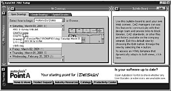
The Open Drawings tab of the Today page allows you to select an existing drawing. When you click this tab, the interface displays a list of the most recently used drawing files, as shown in Figure 2.1. You may select one of the files in the list, or click the Browse button to locate other files. The Browse button opens the Select File dialog box, which enables you to browse your system’s folders for the drawing file you wish to open.
Figure 2.1. The Open Drawings tab in the Today page displays the most recently opened files according to four sorting options.
The other two tabs at the top of the Today page allow you to create new drawings and open a symbol library. Depending on the tab you choose, the Today interface presents you with choices that automate the process of setting up your new drawing’s default setting.
The following sections describe in detail the various ways you can use the Today page to set your drawing’s default values, and provide examples that demonstrate its ease of use.
Starting from Scratch: Understanding AutoCAD’s Default Values
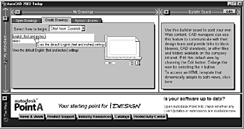
The Start from Scratch option (the second option in the Create Drawings tab of the Today page) is the simplest to use when starting a new drawing. When you choose this option, it presents you with only two choices in the selection area. You can choose English or Metric units of measurement, as shown in Figure 2.2. If you choose English units, AutoCAD creates a new drawing based on the Imperial measurement system, which uses the acad.dwt template file, and sets the drawing boundaries, called LIMITS, to 12×9 inches. If you choose Metric units, AutoCAD creates a new drawing based on the metric measurement system, which uses the acadiso.dwt template file, and sets the drawing limits to 420×297 millimeters.
Figure 2.2. The Start from Scratch option displays only two types of default settings.
When you choose English or Metric units, you are actually setting two system variables: MEASUREMENT and MEASUREINIT. The MEASUREMENT system variable sets the drawing units as either English or Metric for the current drawing, whereas the MEASUREINIT system variable sets the drawing units as either English or Metric for new drawings when they are created.
Specifically, the two system variables control which hatch pattern and linetype files an existing or a new drawing uses when it is opened. When the system variables are set to 0, the English units are set, and AutoCAD uses the hatch pattern file and linetype file designated by the ANSIHatch and ANSILinetype Registry settings. When the system variables are set to 1, the Metric units are set and AutoCAD uses the hatch pattern file and linetype file designated by the ISOHatch and ISOLinetype Registry settings.
Note
Each time you launch AutoCAD and the Today page appears, you may choose the page Close button [X] or simply click in the drawing area. The Close button cancels the Today page and leaves you with a new drawing using the default English or most recent drawing Start from Scratch type for MEASUREMENT and MEASUREINIT, including the associated drawing template and drawing limits. This occurs because AutoCAD stores these values in its system Registry AutoCAD.
Tip
It is much more useful to leave the Today page open and in the background. It provides quick access to your drawings and to starting new drawings, but offers access to the Autodesk Point A Web portal. You will find Point A to be an invaluable resource regardless of your industry discipline.
It is important to determine which system of measurement you will use before starting your drawing because the system of units you select influences how objects appear in your drawing. For example, Figure 2.3 shows two rectangles that contain a hatch pattern. Both hatch patterns are the same (ANSI31), and their rotation and scale are identical: 0 and 1.0000, respectively. However, it is obvious the hatch pattern on the left displays lines much closer together than does the hatch pattern on the right.
Figure 2.3. The MEASUREMENT system variable affects the appearance of hatch patterns when they are inserted in a drawing.
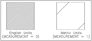
The difference in the two hatch patterns occurs because the hatch pattern on the left was drawn first with the MEASUREMENT system variable set to 0 (English units). Next, the MEASUREMENT system variable was set to 1 (Metric units). Then the same hatch pattern was drawn on the right. This example demonstrates that AutoCAD uses two different hatch pattern files based on the current value of MEASUREMENT. Be sure to choose the correct units of measurement to ensure that AutoCAD inserts the proper hatch patterns and linetypes into your drawing.
Tip
To correct a hatch pattern inserted with the wrong units of measurement, after changing the MEASUREMENT system variable, select the hatch pattern, click the right mouse button, then choose Hatch Edit. After AutoCAD displays the Hatch Edit dialog box, choose the same hatch pattern from the list, then click OK. AutoCAD updates the hatch pattern based on the current units of measurement.
Using Wizards to Automate Settings
AutoCAD provides wizards to help you set up a new drawing. As you complete setting one value, the wizard takes you to the next, using a standard Windows wizard interface that enables you to go to the next default setting, or back to edit previous settings. By using AutoCAD’s wizards, you can quickly set certain default values and change them again if needed.
Understanding the Wizard Selections
When you choose the Wizard option (the third option in the Creates Drawings tab), the Today page offers two wizard choices: The Advanced Setup and the Quick Setup, as shown in Figure 2.4. The Advanced Setup Wizard takes you through five dialog boxes, allowing you to set values for units, angle, angle measure, angle direction, and area. The Quick Setup Wizard offers a subset of these values, removing options for setting the various values related to angles. Specifically, the Quick Setup Wizard enables you to set values for units and area only.
Figure 2.4. The Wizard option offers two methods from which to choose.

The following describes the various values you can set with the Advanced Setup Wizard:
Units. The Units dialog box allows you to set the way linear units are displayed in your drawing.
Angle. The Angle dialog box allows you to set the way angles are displayed in your drawing.
Angle Measure. The Angle Measure dialog box allows you to set the base angle from which all angles are measured (it represents 0 degrees).
Angle Direction. The Angle Direction dialog box allows you to set the direction all angles are measured from the base angle (clockwise or counterclockwise).
Area. The Area dialog box allows you to set the drawing’s limits, which represent the area in which your model should be drawn and contained.
Note
In the Start from Scratch discussion, you learned how to select between English and Metric measuring systems to control the hatch pattern and linetype files AutoCAD uses in a drawing. However, the Units dialog box discussed here controls how units in the selected measurement system are displayed.
The Units dialog box allows you to set how AutoCAD displays measured values, such as the length of a line, the radius of a circle, or the area of a polygon. It also controls how AutoCAD displays coordinate values. For example, if the units are set to Decimal, and you list the values of a circle object in a drawing, AutoCAD displays values as shown:
center point, X=   5.8796  Y=   4.2286  Z=   0.0000
             radius    1.1396
      circumference    7.1601
               area    4.0797
However, if the units are set to Fractional, and you list the values of the same circle, AutoCAD displays values as shown:
center point, X=    5 7/8  Y=    4 1/4  Z=        0
             radius    1 1/8
     circumference    7 3/16
              area    4 1/16
Notice the difference between the two formats. The Decimal format displays values less than one unit as decimals. In contrast, the Fractional format displays values less than one unit as fractions. This is true even though the values for the exact same objects are listed.
Tip
If you use the fractional-based unit settings, measurements will be rounded to the nearest fractional unit.This can lead to drafting inaccuracies if assumed to be exact values. Therefore, if you require precise values, use decimal-based units.
Note
The selected units display mode does not affect AutoCAD’s dimensions, which are controlled by their own system variables.
The Units dialog box also allows you to control the precision of the measured values. In Decimal mode, it represents the number of decimal places displayed for a value. In Fractional mode, it represents the smallest fractional increment displayed for a value (for example, 1/32 or 1/64).
When you select a Units value, you are actually setting the LUNITS system variable. The LUNITS system variable is based on integer values, with each integer value representing a units display mode, as shown in Table 2.1.
| Integer | Display Mode | Example |
|---|---|---|
| 1 | Scientific | 1.1356E+00 |
| 2 | Decimal | 1.1356 |
| 3 | Engineering | 0'–1.1356" |
| 4 | Architectural | 0'–1 1/8" |
| 5 | Fractional | 1 1/8 |
Additionally, another system variable, LUPREC, controls precision for units. Like the LUNITS system variable, LUPREC uses integer values to determine the number of decimal places displayed with a value. The range of acceptable values is 0 through 8. In the case of values displayed in Fractional mode, the integer value represents a fractional increment. Table 2.2 shows examples of the precision display for each value.
| Integer | Decimal | Fractional |
|---|---|---|
| 0 | 0 | 0 |
| 1 | 0.0 | 0–1/2 |
| 2 | 0.00 | 0–1/4 |
| 3 | 0.000 | 0–1/8 |
| 4 | 0.0000 | 0–1/16 |
| 5 | 0.00000 | 0–1/32 |
| 6 | 0.000000 | 0–1/64 |
| 7 | 0.0000000 | 0–1/128 |
| 8 | 0.00000000 | 0–1/256 |
Tip
You can adjust the value of a system variable by typing its name at the Command prompt:, and then entering the desired value.
Note
The selected precision display mode does not affect the accuracy AutoCAD uses in its calculations. All calculations are double-precision and carried out to 16 decimal places.
The Angle dialog box allows you to set how AutoCAD displays angle values, such as the angle of an arc, or the angle between two lines. It also enables you to set the precision of displayed angles.
Like the Units dialog box, the Angle dialog box controls two system variables: AUNITS and AUPREC. When you select an angle value, you are setting the AUNITS system variable. The AUNITS system variable is based on integer values, with each integer value representing a units display mode, as shown in Table 2.3.
| Integer | Display Mode | Example |
|---|---|---|
| 0 | Decimal degrees | 23.9493 |
| 1 | Degrees/minutes/seconds | 23d56'57" |
| 2 | Gradians | 26.6103g |
| 3 | Radians | 0.4180r |
| 4 | Surveyor’s units | N 66d3'3" E |
The AUPREC system variable controls the precision of displayed angles, and functions similarly to the LUPREC system variable, using integer values to determine the number of decimal places displayed with a value. The range of acceptable integer values is 0 through 8. In the case of values displayed in degrees/minutes/seconds or Surveyor’s units, the integer values control the display of minutes and seconds. If the precision value defines the precision beyond minutes and seconds, the seconds are displayed in decimal format. Table 2.4 shows examples of the precision display for each value.
| Integer | Decimal | Surveyor’s Units |
|---|---|---|
| 0 | 8 | N 82d E |
| 1 | 8.2 | N 81d46' E |
| 2 | 8.23 | N 81d46' E |
| 3 | 8.235 | N 81d45'55" E |
| 4 | 8.2347 | N 81d45'55" E |
| 5 | 8.23469 | N 81d45'55.1" E |
| 6 | 8.234689 | N 81d45'55.12" E |
| 7 | 8.2346894 | N 81d45'55.118" E |
| 8 | 8.23468944 | N 81d45'55.1180" E |
Notice that the Surveyor’s units for integer values 1 and 2, and values 3 and 4, respectively, display the same level of precision. This occurs because minutes and seconds must be displayed as full values. This is true because there are 60 minutes of angular arc in one degree, and 60 seconds of angular arc in one minute.
Note
When displaying angles in degrees/minutes/seconds or Surveyor’s units, the ' symbol stands for minutes, not feet, and the " symbol stands for seconds, not inches.
The Angle Measure dialog box allows you to set the base angle from which all angles are measured. AutoCAD uses the default value of 0 degrees being due East. The Angle Measure dialog box allows you to choose from four preset base angles (East, North, West, or South), and allows you to enter your own user-defined base angle. The value for the base angle is stored in the ANGBASE system variable, and can represent any angle value.
Note
The base angle is associated with the X-axis of the current UCS. If you rotate the UCS, the base angle also rotates.
The Angle Direction dialog box works in conjunction with the Angle Measure dialog box and allows you to set the direction all angles are measured from. The only possible directions are counterclockwise or clockwise. The current direction value is held in the ANGDIR system variable, with 0 indicating a counterclockwise direction, and 1 indicating a clockwise direction.
The Area dialog box allows you to set the drawing’s limits, which generally represent the area in which your model is contained or the area within which you will be creating your drawing. The limits are intended to help you manage your drawing.
When you set the width and length of the limits, AutoCAD defines the limits as a rectangle, with its lower-left corner located at coordinates 0,0, and its upper-right corner based on the values you enter for Width and Length. The Width and Length values are stored in the LIMMIN and LIMMAX system variables, respectively.
You can instruct AutoCAD to not allow you to accidentally draw outside the drawing limits, thereby adding a level of error checking to your drawing session. This is called limits checking, and is controlled with the LIMCHECK system variable. By setting the variable to 0, you turn off limits checking, and by setting it to 1, you turn on limits checking. The LIMCHECK variable will only protect you against acquiring points outside the limits. You can copy objects outside limits and position other items as well.
The drawing area within the limits is also the area in which AutoCAD will display its grid. The grid is made up of a series of dots, and is used as a frame of reference when creating objects. The grid is useful for quickly drawing objects based on grid locations. The grid’s visibility is controlled from the Grid button located on the status bar at the bottom of AutoCAD’s screen. You may also press the function key F7 to toggle the grid on and off.
Finally, you can use the limits with the ZOOM command, and when plotting. When zooming, you can select the All option to immediately display the entire Limits area on AutoCAD’s screen. When plotting from model space, you can select the Limits option to plot the entire area defined by the Limits setting.
You have learned how AutoCAD can make starting a drawing easy by using its wizards to walk you through the setup process. Next, you will learn how to take advantage of previous drawing setups by using templates.
Using the Available Templates to Start a Drawing
A template is a drawing file that contains predefined drawing settings and/or geometry, such as a title block, and is used to begin a new drawing. Templates are intended as a quick way to take advantage of an existing drawing that contains the proper drawing settings and base geometry you use in every drawing.
For example, suppose you are creating 10 drawings, and those drawings will use the same units and angle settings, and use the same title block. To minimize your work effort, you can create the drawing once, defining the proper units and angle settings, and inserting the desired title block, then save the drawing as a template. As you begin each new drawing, you select the template file you previously created, which contains the correct units, angle settings, and title block. The template acts as a base for your new drawing, and thereby eliminates a lot of repetitious preparation and setup work.
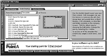
When you choose the Template option (the first option in the Create Drawings tab of the Today page), AutoCAD displays the list of available templates, as shown in Figure 2.5. AutoCAD 2002 comes with 66 predefined template files, and you can add your own. You create a template file by defining the proper units and angle settings, and inserting any desired geometry, and saving the drawing as a .DWT file.
Figure 2.5. The Use a Template feature offers 66 predefined templates.
Customizing and Saving a Template File
Although Autodesk has made a considerable effort to provide a broad array of templates, chances are you will want to customize your own templates. You can do so by modifying one of the template files provided with AutoCAD 2002, or by creating a drawing from scratch.
In the following exercise, you begin with an existing template file, modify a few of its drawing settings, then save the drawing as a new template file.
Exercise 2.1 Creating a Template Drawing
1. |
Launch AutoCAD, and in the Today page, click the Create Drawings tab and choose the Template option from the pop-up list. |
2. |
From the template listing, choose the ANSI B -Color Dependent Plot Styles.dwt template file. Tip When you hover over a selection choice and your cursor changes from an arrow to a hand (depending on your cursor settings) a single-click selection is all that is required to choose the option. This often eliminates the need for an OK button. For instance, the Today page does not have one. |
3. |
At the Command: prompt, type LUPREC
, and then press Enter. |
4. |
Type 2
, and then press Enter. This sets the display of units to two decimal places. |
5. |
At the Command: prompt type AUNITS
, then press Enter. |
6. |
To set the angle display to surveyor’s units, type 4
, then press Enter. |
7. |
At the Command: prompt, type AUPREC
, then press Enter. |
8. |
Type 2
, then press Enter. This sets the angle display to degrees and minutes. |
9. |
From the File menu, choose Save As. |
10. |
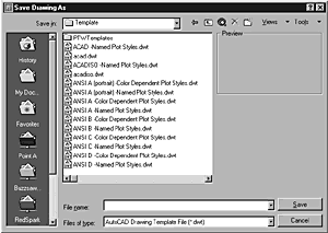
In the Save Drawing As dialog box, from the Files of Type drop-down list, choose AutoCAD Drawing Template File (*.dwt). Note The Today page does not contain a Save As option so the new Save Drawing As dialog is utilized instead. Figure 2.6. To save the drawing as a template file, choose the AutoCAD Drawing Template File (*.dwt) option from the Files of Type drop-down list.
|
11. |
In the File Name edit box, type ANSI B -Survey Units
, then click Save. |
12. |
In the Template Description dialog box that appears, replace the contents with Angles are measured in Survey units, as shown in Figure 2.7, then click OK to save the current drawing as a template file. Figure 2.7. The Template Description dialog box allows you to enter a description for your template file.
|
13. |
To start a new drawing using the template you just created, choose New. |
14. |
In the Today page, from the Create Drawings tab, choose the Template option. Expand the A category if needed. |
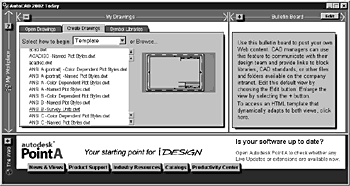
Your newly created template file should appear in the Template list, as shown in Figure 2.8.
Figure 2.8. The new template appears in the Template list.
The capability to create your own custom templates is very powerful. By creating custom template files, you minimize repetitive tasks and reduce errors by using the same templates repeatedly.
Note
The LUPREC, AUPREC, and AUNITS system variables can be set using the Drawing Units dialog box.
So far, you have seen how to control drawing settings using the Startup dialog box. Next, you will learn how to control drawing settings during the current drawing session.
