Chapter 6 Windows 10 Networking
This chapter covers the following subjects:
![]() Configuring TCP/IP Settings: TCP/IP is the primary protocol suite used by computers connecting with each other and the Internet. This section introduces you to the important components of versions 4 and 6 of the TCP/IP protocol suite that you must be familiar with for the 70-697 and 70-698 exams. In this section you are introduced to the various types of IPv4 and IPv6 addresses that are used on Windows-based networks.
Configuring TCP/IP Settings: TCP/IP is the primary protocol suite used by computers connecting with each other and the Internet. This section introduces you to the important components of versions 4 and 6 of the TCP/IP protocol suite that you must be familiar with for the 70-697 and 70-698 exams. In this section you are introduced to the various types of IPv4 and IPv6 addresses that are used on Windows-based networks.
![]() Configuring IP: In this section you learn about the various settings in Windows that enable you to connect to wired or wireless networks, including the Internet. You are also introduced to the wireless networking protocols used by Windows 10 and the available security settings that help protect your connection.
Configuring IP: In this section you learn about the various settings in Windows that enable you to connect to wired or wireless networks, including the Internet. You are also introduced to the wireless networking protocols used by Windows 10 and the available security settings that help protect your connection.
![]() Configuring Network Settings: Network adapters available in Windows 10 include wired Ethernet connections, wireless adapters, Bluetooth PAN adapters, as well as virtual adapters used for tunneling, VPN, and dial-up connectivity. This section shows you how to configure your network adapter settings, networking configurations, and other options specific to adapters and adapter types. When connecting to wireless networks, manually and automatically, it is important to make sure that the network access points that Windows finds and accesses are the intended networks. This section discusses ways for managing preferred wireless networks and how each connection should be handled.
Configuring Network Settings: Network adapters available in Windows 10 include wired Ethernet connections, wireless adapters, Bluetooth PAN adapters, as well as virtual adapters used for tunneling, VPN, and dial-up connectivity. This section shows you how to configure your network adapter settings, networking configurations, and other options specific to adapters and adapter types. When connecting to wireless networks, manually and automatically, it is important to make sure that the network access points that Windows finds and accesses are the intended networks. This section discusses ways for managing preferred wireless networks and how each connection should be handled.
This chapter covers the following objectives for the 70-697 and 70-698 exam:

Configure IP settings: Configure and support IPv4 and IPv6 network settings; configure name resolution, connect to a network, configure network locations.

Configure networking settings: Connect to a wireless network, manage preferred wireless networks, configure network adapters, configure location-aware printing; troubleshoot network issues.
Connectivity between Windows 10 computers and other networks (inclusive of the Internet and other computers) is provided in a variety of ways. Windows 10 computers utilize a variety of tools, applications, and protocols for connecting to networks. You learn about the Network and Sharing Center, which consolidates many of these applications and utilities into one convenient location from which you can create and manage different types of network connections as well as file and printer sharing. This chapter starts by introducing networking components, including how to install, configure, and manage them:
![]() Dial-up networking
Dial-up networking
![]() Wireless networking
Wireless networking
![]() Configuring network adapters
Configuring network adapters
![]() Location-aware printing
Location-aware printing
Not only do you explore each of these components in this chapter, you also look at their features and dependencies as they exist within the Windows 10 operating system.
“Do I Know This Already?” Quiz
The “Do I Know This Already?” quiz allows you to assess whether you should read this entire chapter or simply jump to the “Exam Preparation Tasks” section for review. If you are in doubt, read the entire chapter. Table 6-1 outlines the major headings in this chapter and the corresponding “Do I Know This Already?” quiz questions. You can find the answers in Appendix A, “Answers to the ‘Do I Know This Already?’ Quizzes.”
Table 6-1 “Do I Know This Already?” Foundation Topics Section-to-Question Mapping
Foundation Topics Section |
Questions Covered in This Section |
Configuring TCP/IP Settings |
1–7 |
Configuring IP |
8–10 |
Configuring Network Settings |
11–15 |
Caution
The goal of self-assessment is to gauge your mastery of the topics in this chapter. If you do not know the answer to a question or are only partially sure of the answer, you should mark that question as wrong for purposes of the self-assessment. Giving yourself credit for an answer you correctly guess skews your self-assessment results and might provide you with a false sense of security.
1. Which of the following are component protocols contained within TCP/IP? (Choose three.)
a. User Datagram Protocol (UDP)
b. Internet Control Message Protocol (ICMP)
c. Dynamic Host Configuration Protocol (DHCP)
d. Address Resolution Protocol (ARP)
2. You need to ensure that your IPv4-enabled computer can access other subnets on your company’s network, as well as the Internet. Which addressing component should you ensure is specified properly?
a. IP address
b. Subnet mask
c. Default gateway
d. DNS server address
e. WINS address
3. Your computer is configured with the IP address 131.107.24.5. To which class does this IP address belong?
a. A
b. B
c. C
d. D
e. E
4. Your company is making use of the 192.168.21.0/24 network. This network address is an example of what type of address notation?
a. Windows Internet Name Service (WINS)
b. Unicast
c. Multicast
d. Classless interdomain routing (CIDR)
5. Your company has transitioned to using the IPv6 protocol, and you are responsible for configuring Internet servers that need direct access to the Internet. Which of the following types of IPv6 addresses should you use for this purpose?
a. Global unicast
b. Link-local unicast
c. Site-local unicast
d. Multicast
e. Anycast
6. Your computer is using an IPv6 address on the fe80::/64 network. What type of IPv6 address is this?
a. Global unicast
b. Link-local unicast
c. Site-local unicast
d. Teredo
7. Your computer is using an IPv6 address that includes the 32-bit prefix of 2001::/32. What type of IPv6 address prefix is this?
a. Global unicast
b. Link-local unicast
c. Site-local unicast
d. Teredo
8. You need to configure a client computer running Windows 10 Pro to respond to three different DNS servers in order to resolve all names on the network. What should you do?
a. From the General tab of the Internet Properties dialog box, select the Use the Following DNS Server Addresses option and type the IP addresses of the three DNS servers in the text boxes provided.
b. From the General tab of the Internet Properties dialog box, select the Use the Following DNS Server Addresses option and type the IP addresses of the two most used DNS servers in the text boxes provided. Then select the Alternate Configuration tab and type the IP address of the third DNS server at this tab.
c. From the General tab of the Internet Properties dialog box, select the Use the Following DNS Server Addresses option and click the Advanced button. On the Advanced TCP/IP Settings dialog box that appears, click Add and type the three DNS server IP addresses, one at a time. Then ensure that they are sequenced in the order they will most likely need to be accessed.
d. You cannot specify more than two DNS servers at the client computer; you must configure the DHCP server to supply the required DNS server IP addresses.
9. Your network is configured to use DHCP for assignment of IP addresses and DNS servers. Which of the following options should you ensure are selected in the Internet Protocol Version 4 (TCP/IPv4) Properties dialog box? (Choose two.)
a. Obtain an IP Address Automatically
b. Use the Following IP Address
c. Obtain DNS Server Address Automatically
d. Use the Following DNS Server Addresses
10. Your computer is configured to use the IPv4 address 169.254.183.32. What system is being used by your computer?
a. Dynamic Host Configuration Protocol (DHCP)
b. Automatic Private Internet Protocol Addressing (APIPA)
c. Private IPv4 network addressing
d. Alternate IP configuration
11. Your network provider charges for all of your bandwidth based on the amount of data transferred over the connection. You want to set up a wireless connection to ensure that the amount of data transferred while connected is minimized. What setting should you use?
a. Estimated data usage
b. Turn sharing on or off
c. Metered connection
d. Dial-up connection speed
12. You currently have several wireless networks that you connect to frequently. Your home network uses WEP, the engineering department near your office uses WPA2-Personal, the coffee shop around the corner uses Open Wi-Fi, and the conference room near your office uses WEP. You hosted a demonstration in the conference room before you left the office yesterday, and then you used your home AP to VPN to the company network last night. When you arrive at the office in the morning and turn on your laptop, which network will your Windows 10 computer attempt to connect with first?
a. Your home network AP
b. The conference room
c. The engineering department
d. The coffee shop
13. You have been traveling a great deal with your Windows 10 laptop and want to clean up the leftover wireless network profiles that you will probably not use again in the near future. How can you delete the wireless profiles?
a. Select each from the Network list, right-click, and select Forget This Network.
b. Use the netsh command netsh wlan delete for each profile.
c. Use the Network and Sharing center to delete the network connections.
d. You cannot delete the profiles.
14. You need to make changes to the Advanced properties of a network adapter device. To access the properties, you open the Change Adapter settings from the Network and Sharing Center, access the adapter properties from the right-click menu, and then the NIC properties using the Configure button. This is similar to the properties from the Device Manager device properties, but some settings are unavailable. What can you not configure from this dialog that is available when using Device Manager?
a. Advanced properties
b. Driver details
c. Power Management
d. Resources
15. Which of the following Advanced properties of a network adapter are available for a wireless connection? (Choose all that apply.)
a. 802.11n mode
b. Speed and Duplex
c. Transmit Buffers
d. Preferred Band
e. Receive Buffers
Foundation Topics
Configuring TCP/IP Settings
To favor seamless integration with the Internet, Microsoft has standardized on the use of TCP/IP and no longer uses older, proprietary network protocol suites that were once common. Since its introduction of Active Directory in Windows 2000, Microsoft has made TCP/IP the protocol suite required for Windows networks that use Active Directory. This is largely because of the Active Directory’s dependence upon Domain Name System (DNS) to provide the name and address resolution for all Active Directory resources.
TCP/IP is a suite of protocols governing the transmission of data across computer networks and the Internet. The following is a brief description of the major protocols that you should be aware of:
![]() Transmission Control Protocol (TCP): Provides connection-oriented, reliable communication between two hosts, typically involving large amounts of data. Note that a host includes any device on the network (such as a computer or router) that is configured for TCP/IP. This kind of communication also involves acknowledgments that data has been correctly received.
Transmission Control Protocol (TCP): Provides connection-oriented, reliable communication between two hosts, typically involving large amounts of data. Note that a host includes any device on the network (such as a computer or router) that is configured for TCP/IP. This kind of communication also involves acknowledgments that data has been correctly received.
![]() User Datagram Protocol (UDP): Used for fast, non-connection-oriented communications with no guarantee of delivery, typically small, short bursts of data. Applications using UDP data transmission are responsible for checking their data’s integrity.
User Datagram Protocol (UDP): Used for fast, non-connection-oriented communications with no guarantee of delivery, typically small, short bursts of data. Applications using UDP data transmission are responsible for checking their data’s integrity.
![]() Internet Protocol (IP): Handles, addresses, and routes packets between hosts on a network. It performs this service for all other protocols in the TCP/IP protocol suite.
Internet Protocol (IP): Handles, addresses, and routes packets between hosts on a network. It performs this service for all other protocols in the TCP/IP protocol suite.
![]() Internet Control Message Protocol (ICMP): Enables hosts on a TCP/IP network to share status and error information. It is specifically responsible for reporting errors and messages regarding the delivery of IP datagrams. It is not responsible for error correction. Higher layer protocols use information provided by ICMP to recover from transmission problems. The ping command uses ICMP to check connectivity to remote computers.
Internet Control Message Protocol (ICMP): Enables hosts on a TCP/IP network to share status and error information. It is specifically responsible for reporting errors and messages regarding the delivery of IP datagrams. It is not responsible for error correction. Higher layer protocols use information provided by ICMP to recover from transmission problems. The ping command uses ICMP to check connectivity to remote computers.
![]() Address Resolution Protocol (ARP): Used to resolve the IP address of the destination computer to the physical or Media Access Control (MAC) address, which is a unique 12-digit hexadecimal number that is burned into ROM on every network adapter card.
Address Resolution Protocol (ARP): Used to resolve the IP address of the destination computer to the physical or Media Access Control (MAC) address, which is a unique 12-digit hexadecimal number that is burned into ROM on every network adapter card.
These are only a few of the many protocols that make up the TCP/IP protocol suite. If you need additional information on these protocols and details on the other protocols that make up TCP/IP, refer to any book that specializes in computer internetworking.
By default, the earliest versions of Windows used version 4 of the IP protocol, simply known as IPv4. With its 32-bit address space, this version has performed admirably well in the more than 30 years since its initial introduction. However, with the rapid growth of the Internet in recent years, its address space has approached exhaustion, and security concerns have increased. Consequently, the Internet Engineering Task Force (IETF) introduced version 6 of the IP protocol with Request for Comment (RFC) 1883 in 1995 and updated with RFCs 2460, 3513, and 4193 in more recent years. Simply known as IPv6, this protocol provides for 128-bit addressing, which allows for a practically infinite number of possible addresses, as well as the following benefits:
![]() An efficient hierarchical addressing scheme: IPv6 addresses are designed to enable an efficient, hierarchical, and summarizable routing scheme, making way for multiple levels of Internet service providers (ISPs), which is becoming more common nowadays.
An efficient hierarchical addressing scheme: IPv6 addresses are designed to enable an efficient, hierarchical, and summarizable routing scheme, making way for multiple levels of Internet service providers (ISPs), which is becoming more common nowadays.
![]() Simpler routing tables: Backbone routers on the Internet are more easily configured for routing packets to their destinations.
Simpler routing tables: Backbone routers on the Internet are more easily configured for routing packets to their destinations.
![]() Stateful and stateless address configuration: IPv6 simplifies host configuration with the use of stateful address configuration (configuring IP addresses in the presence of a Dynamic Host Configuration Protocol [DHCP] server) or the use of stateless address configuration (configuring IP addresses in the absence of a DHCP server). Stateless address configuration enables the automatic configuration of hosts on a subnetwork according to the addresses displayed by available routers.
Stateful and stateless address configuration: IPv6 simplifies host configuration with the use of stateful address configuration (configuring IP addresses in the presence of a Dynamic Host Configuration Protocol [DHCP] server) or the use of stateless address configuration (configuring IP addresses in the absence of a DHCP server). Stateless address configuration enables the automatic configuration of hosts on a subnetwork according to the addresses displayed by available routers.
![]() Improved security: IPv6 includes standards-based support for IP Security (IPsec). In fact, IPv6 requires IPsec support. You can configure IPsec connection security rules for IPv6 in the same fashion as with IPv4. IPsec is discussed further in Chapter 16, “Configuring and Maintaining Network Security.”
Improved security: IPv6 includes standards-based support for IP Security (IPsec). In fact, IPv6 requires IPsec support. You can configure IPsec connection security rules for IPv6 in the same fashion as with IPv4. IPsec is discussed further in Chapter 16, “Configuring and Maintaining Network Security.”
![]() Support for Link-Local Multicast Name Resolution (LLMNR): This enables IPv6 and IPv4 clients on a single subnet to resolve each other’s names without the need for a DNS server or using NetBIOS over TCP/IP.
Support for Link-Local Multicast Name Resolution (LLMNR): This enables IPv6 and IPv4 clients on a single subnet to resolve each other’s names without the need for a DNS server or using NetBIOS over TCP/IP.
![]() Improved support for Quality of Service (QoS): IPv6 header fields improve the identification and handling of network traffic from its source to destination, even when IPsec encryption is in use.
Improved support for Quality of Service (QoS): IPv6 header fields improve the identification and handling of network traffic from its source to destination, even when IPsec encryption is in use.
![]() Extensibility: You can add extension headers after the IPv6 packet header, which enable the inclusion of new features as they are developed in years to come.
Extensibility: You can add extension headers after the IPv6 packet header, which enable the inclusion of new features as they are developed in years to come.
By using a TCP/IP implementation known as the Next Generation TCP/IP stack (first included with Windows Vista), Windows 10 enables a dual IP layer architecture enabling the operation of both IPv4 and IPv6 at the same time. Unlike with Windows XP and older Windows versions, Windows 10 does not require you to install a separate IPv6 component; IPv6 is installed and enabled by default.
Note
For more introductory information on IPv6, refer to “Microsoft’s Objectives for IP Version 6” at http://technet.microsoft.com/en-us/library/bb726949.aspx.
Configuring and Supporting TCP/IP Version 4 Settings
Much of TCP/IPv4 is transparent to users and to administrators. The administrator may need to configure the address information applied to the network interface. Table 6-2 describes this address information.

Table 6-2 IPv4 Addressing Components
Addressing Component |
Description |
IP address |
The unique, logical 32-bit address, which identifies the computer (called a host or node) and the subnet on which it is located. The IP address is displayed in dotted decimal notation (each decimal represents an octet of binary ones and zeros). For example, the binary notation of an address may be 10000000.00000001.00000001.00000011, which in dotted decimal notation is written as 128.1.1.3. |
Subnet mask |
The subnet mask is applied to an IP address to determine the subnetwork address and the host address on that subnet. All hosts on the same subnet must have the same subnet mask for them to be correctly identified. If a mask is incorrect, both the subnet and the host address will be wrong. (For example, if you have an IP address of 128.1.1.3, and an incorrect mask of 255.255.128.0, the subnet address would be 128.1.0 and the host address would be 1.3. If the correct subnet mask is 255.255.255.0, the subnet address would be 128.1.1 and the host address would be 3.) |
Default gateway |
The address listed as the default gateway is the location on the local subnet to which the local computer will send all data meant for other subnets. In other words, this is the IP address for a router that is capable of transmitting the data to other networks. |
DNS server address |
The place where names of IP hosts are sent so that the DNS server will respond with an IP address. This process is called name resolution. DNS is a distributed database of records that maps names to IP addresses, and vice versa. A HOSTS file that maps names to IP addresses can be placed on the local computer and used instead of DNS, which renders this an optional setting, although it is rare that a network is small enough to make a HOSTS file more efficient than a DNS server. When a user types in a DNS name, such as BlakePC.mydomain.local, the computer sends the name to the DNS server. If the name is one that the DNS server knows, it sends back the IP address. Otherwise, the DNS server sends the name request to a higher-level DNS server, and this recursive process continues until either the IP address is found and returned to the original requestor or until all avenues have been exhausted and the original requestor is notified that the name cannot be found. |
Windows Internet Name Service (WINS) address |
The WINS server address is the location where network computers send requests to resolve NetBIOS names to IP addresses. WINS is used on Microsoft Windows networks where older Windows computers or applications require NetBIOS naming. When a user types in a NetBIOS name, such as BLAKEPC, the computer sends the name to the WINS server. Because WINS is a flat-file database, it returns an IP address or a Name Not Found message. WINS server addresses, like DNS server addresses, are optional. A computer can use a local LMHOSTS file to map the NetBIOS names to IP addresses rather than use WINS. |
Static IPv4 Addressing
IP addresses indicate the same type of location information as a street address. A building on a street has a number, and when you add that number to the street name, you can find it fairly easily because the number and the street will be unique within a city. This type of address scheme—an individual address plus a location address—allows every computer on the Internet to be uniquely identified.
A static IP address is one that is permanently assigned to a computer on the network. Certain computers (such as routers or servers) require static IP addresses because of their functions. Client computers are more often assigned dynamic addresses because they are more likely to be moved around the network or retired and replaced. DSL and cable modem users are usually given a dynamic IP address (but this doesn’t change for a long time, generally until the cable company next reconfigures the network), whereas dial-up users are provided with dynamic addresses that change each time the user connects to the network.
As discussed earlier, IP addresses consist of two parts: one that specifies the network and one part that specifies the computer. These addresses are further categorized with classes, as described in Table 6-3.
Table 6-3 IPv4 Address Classes
Class |
Dotted Decimal Hosts per Range |
First Octet Binary |
Usage |
Number of Networks |
Number of Hosts per Network |
A |
1.0.0.0–126.255.255.255 |
0xxxxxxx |
Large networks/ ISPs |
126 |
16,777,214 |
B |
128.0.0.0–191.255.255.255 |
10xxxxxx |
Large or mid-size ISPs |
16,384 |
65,534 |
C |
192.0.0.0–223.255.255.255 |
110xxxxx |
Small networks |
2,097,152 |
254 |
D |
224.0.0.0–239.255.255.255 |
1110xxxx |
Multicasting |
N/A |
N/A |
E |
240.0.0.0–254.255.255.255 |
1111xxxx |
Reserved for future use |
N/A |
N/A |
Loopback |
127.0.0.1–127.255.255.255 |
01111111 |
Loopback testing |
N/A |
N/A |
Note
The concept of loopback testing is the usage of a predefined IP address that a computer can dial itself up to see whether the TCP/IP stack is properly set up. If TCP/IP is configured, you should be able to run the ping 127.0.0.1 command when troubleshooting a connectivity problem.
The portion of the address that decides on which network the host resides varies based on the class, and, as you will see further on, the subnet mask. In the following list, the uppercase Ns represent the part of the IP address that specifies the network, and the lowercase Cs represent the part of the address that specifies the computer. This explains why there are differing numbers of networks per class and different numbers of hosts per network, as listed in Table 6-3.
![]() Class A: NNNNNNNN.cccccccc.cccccccc.cccccccc
Class A: NNNNNNNN.cccccccc.cccccccc.cccccccc
![]() Class B: NNNNNNNN.NNNNNNNN.cccccccc.cccccccc
Class B: NNNNNNNN.NNNNNNNN.cccccccc.cccccccc
![]() Class C: NNNNNNNN.NNNNNNNN.NNNNNNNN.cccccccc
Class C: NNNNNNNN.NNNNNNNN.NNNNNNNN.cccccccc
These address portions coincide with the default subnet masks for each address class. A Class A subnet mask is 255.0.0.0, a Class B subnet mask is 255.255.0.0, and a Class C subnet mask is 255.255.255.0.
Subnet masks enable you to reconfigure what constitutes the network portion and what constitutes the computer portion. When you apply the subnet mask to the IP address by using a bitwise logical AND operation, the result is a network number. A bitwise logical AND operation adds the bit, whether 1 or 0, to the corresponding bit in the subnet mask. If the subnet mask bit is a 1, the corresponding IP address bit is passed through as a result. If the subnet mask bit is a 0, a zero bit is passed through. For example, if the IP address is 141.25.240.201, you will have the following:
IP address: 10001101.00011001.11110000.11001001
Subnet mask: 11111111.11111111.00000000.00000000
Result from bitwise logical AND
Network: 10001101.00011001.00000000.00000000
This shows the network address as 141.25.0.0 and the host address to 0.0.240.201. If you add bits to the mask, you will be able to have additional subnetworks when you perform a bitwise logical AND, and each subnetwork will have fewer hosts because fewer bits are available for the host portion of the address. If you use the same address and add five bits to the subnet mask, you would receive the following:
IP address: 10001101.00011001.11110000.11001001
Subnet mask: 11111111.11111111.11111000.00000000
Result from bitwise logical AND
Network: 10001101.00011001.11110000.00000000
In this case, the subnet mask changes the network address to 141.25.240.0. The host address changes to 0.0.0.201. Other IP addresses that are under the default Class B subnet mask that would otherwise be part of the same network (such as 140.25.192.15 and 140.25.63.12) are now on different subnets.
For an organization with a large number of physical networks where each requires a different subnet address, you can use the subnet mask to segment a single address to fit the network. You can easily calculate how many subnets and hosts you will receive when you subnet a network. The formula is 2n−2, where n is the number of bits. 2n is the number 2 raised to the power of the number of bits, and that result minus 2 (the addresses represented by all 1s and all 0s) equals the available subnets or hosts. Therefore, if you have a subnet of 5 bits (as previously shown), you are able to achieve 25−2 = 32−2 = 30 subnets. Because there are 11 bits left for host addresses, each subnet will have 211−2 = 2048−2 = 2,046 hosts.
Classless Interdomain Routing
When you multiply 2046 by 30, you will see that you have 61,380 addresses available for network hosts and that you “lost” 4,154 addresses. This is the problem that classless interdomain routing (CIDR) solves.
When you consider that a Class A address has over 16 million host addresses and that no organization with a Class A address has managed to utilize each of those addresses, you realize the use of classful addressing (an IP addressing system that does not segment the network into smaller subnetworks) is extremely wasteful. CIDR was developed to prevent the Internet from running out of IP addresses by reusing some of the unused addresses and expanding the addresses available when subnetting.
With CIDR, a subnet mask is not considered separate from the network portion of the mask. Instead, whatever portion of the mask is used for the network determines how many networks there are. This means that a company can “supernet” two (or more) Class C addresses to put more than 254 hosts on a single physical network. Supernetting is the process of subtracting bits from the default subnet mask. This adds bits to the host portion, increasing the number of hosts available.
CIDR notation allows you to simply specify the number of bits that are used for a mask after the IP address. For example, 192.168.1.0 with a subnet mask of 255.255.255.0 is written as 192.168.1.0/24. If the address were supernetted, it could be 192.168.1.0/22.
Private IPv4 Networks
IPv4 specifications define sets of networks that are specified as private IPv4 networks. The private IP address classes are used on private networks that utilize Network Address Translation or proxy services to communicate on the Internet. Internet routers are preconfigured to not forward data that contains these IP addresses. Table 6-4 describes these networks.
Table 6-4 Private IPv4 Network Addresses
Class |
Dotted Decimal Hosts per Range |
First Octet Binary |
Number of Networks |
Number of Hosts per Network |
A |
10.0.0.0–10.255.255.254 |
00001010 |
1 |
16,777,214 |
B |
172.16.0.0–172.31.255.254 |
10101100 |
1 |
65,534 |
C |
192.168.0.0–192.168.255.254 |
11000000 |
254 |
254 |
Note
For more information on TCP/IP version 4, refer to “IPv4 Addressing” at https://technet.microsoft.com/en-us/library/dd379547(v=ws.10).aspx and “Fundamentals of Classful IPv4 addressing” at https://learningnetwork.cisco.com/docs/DOC-12872.
Configuring and Supporting TCP/IP Version 6 Settings
The 128-bit addressing scheme used by IPv6 enables an unimaginably high number of 3.4 × 1038 addresses, which equates to a total of 6.5 × 10²³ addresses for every square meter of the Earth’s surface. Consequently, this is a complicated addressing scheme, as described in the following sections.
IPv6 Address Syntax
Whereas IPv4 addresses use dotted-decimal format as explained earlier in this chapter, IPv6 addresses are subdivided into 16-bit blocks. Each 16-bit block is portrayed as a 4-digit hexadecimal number and is separated from other blocks by colons. This addressing scheme is referred to as colon-hexadecimal.
For example, a 128-bit IPv6 address written in binary could appear as follows:
0011111111111110 1111111111111111 0010000111000101 0000000000000000 0000001010101010 0000000011111111 1111111000100001 0011101000111110
The same address written in colon-hexadecimal becomes 3ffe:ffff:21a5:0000:00ff:fe21:5a3e.
You can remove any leading zeros, converting this address to 3ffe:ffff:21a5::ff:fe21:5a3e.
In this notation, note that the block that contained all zeros appears as “::”, which is called double-colon.
IPv6 Prefixes
Corresponding to the network portion of an IPv4 address is the prefix, which is the part of the address containing the bits of the subnet prefix. IPv6 addresses do not employ subnet masks; they use the same CIDR notation used with IPv4. For example, an IPv6 address prefix could be 3ffe:ffff:21a5::/64, where 64 is the number of bits employed by the address prefix.
Types of IPv6 Addresses
IPv6 uses the following three types of addresses:
![]() Unicast: Represents a single interface within the typical scope of unicast addresses. In other words, packets addressed to this type of address are to be delivered to a single network interface. Unicast IPv6 addresses include global unicast, link-local, site-local, and unique local addresses. Two special addresses are also included: unspecified addresses (all zeros, equivalent to the IPv4 address of 0.0.0.0) and the loopback address, which is 0:0:0:0:0:0:0:1 or ::1, which is equivalent to the IPv4 address of 127.0.0.1.
Unicast: Represents a single interface within the typical scope of unicast addresses. In other words, packets addressed to this type of address are to be delivered to a single network interface. Unicast IPv6 addresses include global unicast, link-local, site-local, and unique local addresses. Two special addresses are also included: unspecified addresses (all zeros, equivalent to the IPv4 address of 0.0.0.0) and the loopback address, which is 0:0:0:0:0:0:0:1 or ::1, which is equivalent to the IPv4 address of 127.0.0.1.
![]() Multicast: Represents multiple interfaces to which packets are delivered to all network interfaces identified by the address. Multicast addresses have the first eight bits set to ones, so begin with “ff”.
Multicast: Represents multiple interfaces to which packets are delivered to all network interfaces identified by the address. Multicast addresses have the first eight bits set to ones, so begin with “ff”.
![]() Anycast: Also represents multiple interfaces. Anycast packets are delivered to a single network interface that represents the nearest (in terms of routing hops) interface identified by the address.
Anycast: Also represents multiple interfaces. Anycast packets are delivered to a single network interface that represents the nearest (in terms of routing hops) interface identified by the address.
Table 6-5 provides additional details on the IPv6 classes and subclasses.
Table 6-5 IPv6 Address Classes and Subclasses
Class |
Address Prefix |
Additional Features |
First Binary Bits |
Usage |
Global unicast |
2000::/3 |
Use a global routing prefix of 45 bits (beyond the initial 001 bits), which identifies a specific organization’s network, a 16-bit subnet ID, which identifies up to 54,536 subnets within an organization’s network, and a 64-bit interface ID, which indicates a specific network interface within the subnet. |
001 |
Globally routable Internet addresses that are equivalent to the public IPv4 addresses |
Link-local unicast |
fe80::/64 |
Equivalent to APIPA-configured IPv4 addresses in the 169.254.0.0/16 network prefix. |
111111101000 |
Used for communication between neighboring nodes on the same link. These addresses are assigned automatically when you configure automatic addressing in the absence of a DHCP server. |
Site-local unicast |
fec0::/10 |
Equivalent to the private IPv4 address spaces mentioned previously in Table 6-4. Prefix followed by a 54-bit subnet ID field within which you can establish a hierarchical routing structure within your site. |
111111101100 |
Used for communication between nodes located in the same site. |
Unique local IPv6 unicast |
fc00::/7 |
Prefix followed by a local (L) flag, a 40-bit global ID, a 16-bit subnet ID, and a 64-bit interface ID. |
11111100 |
Provide addresses that are private to an organization but unique across all the organization’s sites. |
Multicast |
ff |
Use the next 4 bits for flags (Transient [T], Prefix [P], and Rendezvous Point Address [R]), the following 4 bits for scope (determines where multicast traffic is forwarded), and the remaining 112 bits for a group ID. |
11111111 |
Multiple interfaces to which packets are delivered to all network interfaces identified by the address. |
Anycast |
(from unicast addresses) |
Assigned from the unicast address space with the same scope as the type of unicast address within which the anycast address is assigned. |
(varies) |
Only utilized as destination addresses assigned to routers. |
Note
Site-local IPv6 addresses are equivalent to the private IPv4 addresses mentioned in Table 6-4. You can access site-local addresses only from the network in which they are located; they are not accessible from external networks such as the Internet.
Note
For more information on IPv6 and its latest enhancements as it relates to Windows 10, refer to “Internet Protocol Version 6 (IPv6) Overview” at http://technet.microsoft.com/en-us/library/hh831730.
Compatibility Between IPv4 and IPv6 Addresses
To assist in the migration from IPv4 to IPv6 and their coexistence, several additional address types are used, as follows:
![]() IPv4-compatible addresses: Nodes communicating between IPv4 and IPv6 networks can use an address represented by 0:0:0:0:0:0:w.x.y.z, where w.x.y.z is the IPv4 address in dotted-decimal.
IPv4-compatible addresses: Nodes communicating between IPv4 and IPv6 networks can use an address represented by 0:0:0:0:0:0:w.x.y.z, where w.x.y.z is the IPv4 address in dotted-decimal.
![]() IPv4-mapped address: An IPv4-only node is represented as ::ffff:.w.x.y.z to an IPv6 node. This address type is used only for internal representation and is never specified as a source or destination address of an IPv6 packet.
IPv4-mapped address: An IPv4-only node is represented as ::ffff:.w.x.y.z to an IPv6 node. This address type is used only for internal representation and is never specified as a source or destination address of an IPv6 packet.
![]() Teredo address: Teredo is a tunneling communication protocol that enables IPv6 connectivity between IPv6/IPv4 nodes across Network Address Translation (NAT) interfaces, thereby improving connectivity for newer IPv6-enabled applications on IPv4 networks. Teredo is described in RFC 4380. Teredo makes use of a special IPv6 address that includes the following components in the sequence given:
Teredo address: Teredo is a tunneling communication protocol that enables IPv6 connectivity between IPv6/IPv4 nodes across Network Address Translation (NAT) interfaces, thereby improving connectivity for newer IPv6-enabled applications on IPv4 networks. Teredo is described in RFC 4380. Teredo makes use of a special IPv6 address that includes the following components in the sequence given:
![]() A 32-bit Teredo prefix, which is 2001::/32 in Windows Vista/7/8/10 and Windows Server 2008/2012/2016.
A 32-bit Teredo prefix, which is 2001::/32 in Windows Vista/7/8/10 and Windows Server 2008/2012/2016.
![]() The 32-bit IPv4 address of the Teredo server involved in creating this address.
The 32-bit IPv4 address of the Teredo server involved in creating this address.
![]() A 16-bit Teredo flag field and an obscured 16-bit UDP port interface definition.
A 16-bit Teredo flag field and an obscured 16-bit UDP port interface definition.
![]() An obscured external IPv4 address corresponding to all Teredo traffic across the Teredo client interface.
An obscured external IPv4 address corresponding to all Teredo traffic across the Teredo client interface.
![]() 6-to-4 address: Two nodes running both IPv4 and IPv6 across an IPv4 routing infrastructure use this address type when communicating with each other. You can form the 6-to-4 address by combining the prefix 2002::/16 with the 32-bit public IPv4 address to form a 48-bit prefix. This tunneling technique is described in RFC 3056.
6-to-4 address: Two nodes running both IPv4 and IPv6 across an IPv4 routing infrastructure use this address type when communicating with each other. You can form the 6-to-4 address by combining the prefix 2002::/16 with the 32-bit public IPv4 address to form a 48-bit prefix. This tunneling technique is described in RFC 3056.
Note
More information on compatibility addresses and technologies used for transition to IPv6 is available in “Internet Protocol Version 6, Teredo, and Related Technologies in Windows 7 and Windows Server 2008 R2” at http://technet.microsoft.com/en-us/library/ee126159(WS.10).aspx. Although this paper was written for Windows 7 and Windows Server 2008 R2, the technologies involved are largely unchanged for Windows 10 and Windows Server 2016.
Configuring IP Settings
Now that you understand the workings of the TCP/IP protocol suite, we turn our attention to the following aspects of configuring IP settings on a Windows 10 computer:
![]() Configuring Name Resolution: Computers on the network are identified by their computer names that are assigned when Windows 10 is installed, or later when a user changes the initially assigned computer name. It is necessary to resolve this name to an IPv4 or IPv6 address so that the computer can be accessed from another one on the network.
Configuring Name Resolution: Computers on the network are identified by their computer names that are assigned when Windows 10 is installed, or later when a user changes the initially assigned computer name. It is necessary to resolve this name to an IPv4 or IPv6 address so that the computer can be accessed from another one on the network.
![]() Connect to Network: Searches for the wireless router or access point you want to configure and then attempts to configure this device for you. Although the wizard states that it might take up to 90 seconds to display unconfigured devices, this process can take considerably longer.
Connect to Network: Searches for the wireless router or access point you want to configure and then attempts to configure this device for you. Although the wizard states that it might take up to 90 seconds to display unconfigured devices, this process can take considerably longer.
![]() Configure Network Locations: Enables you to connect directly to another wireless-enabled computer without the need for a wireless access point. If you do set up a connection of this type, you are disconnected from other wireless networks.
Configure Network Locations: Enables you to connect directly to another wireless-enabled computer without the need for a wireless access point. If you do set up a connection of this type, you are disconnected from other wireless networks.
Configuring Name Resolution
As previously noted, Windows 10 uses DNS as its primary name resolution service. DNS is the name resolution service used by all servers on the Internet; when you type a URL into the address box in Internet Explorer or any other browser, DNS resolves this URL into an IP address so that you can obtain the desired website.
Note
If your network includes a DNS server, this server is used directly for any name resolution requirements within the network. When a client requests an Internet resource such as www.microsoft.com, an iterative name resolution process occurs in which the local DNS server accesses a series of Internet DNS servers to obtain the IP address of the requested resource. Each server that is accessed knows the locations of one level of servers within the hierarchical DNS namespace (in other words, is authoritative for this level by possessing in its database what is known as an A [address] resource record, which holds the hostname to IPv4 address mapping). For example, the following happens when you type http://www.Microsoft.com into your web browser:
1. The local DNS server checks with a root server on the Internet to locate the IP address of a server that is authoritative for .com addresses.
2. The .com server on the Internet locates the IP address of a server that is author-itative for Microsoft.com addresses.
3. The Microsoft.com server on the Internet locates the IP address of the www.Microsoft.com web server.
4. These servers return the required IP address to the client, whose browser then displays the home page of the requested website.
The Local Area Connection Properties dialog box enables you to configure your computer to access a DNS server, as outlined in the following procedure:
Step 1. Right-click the Start button and select Network Connections.
Step 2. Find the appropriate network adapter from the list, right-click, and then select Properties from the context menu.
Step 3. Locate Internet Protocol Version 4 (TCP/IPv4) from the list of items, select it, and then click the Properties button. The Properties box will look like the one in Figure 6-1.
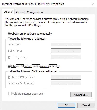
Figure 6-1 Internet Protocol Version 4 (TCP/IPv4) Properties Box
Step 4. If your network is configured to use DHCP to automatically configure client computers with the address of the DNS server, you need only ensure that the Obtain DNS Server Address Automatically option is selected.
Step 5. If your network is not configured with DHCP, click the Use the Following DNS Server Addresses option and type the IP address for at least one DNS server.
Step 6. Click Advanced to bring up the Advanced TCP/IP Settings dialog box shown in Figure 6-2.

Figure 6-2 Advanced TCP/IP Settings Enabling You to Configure Custom Network Settings
Step 7. Click the DNS tab to display the settings shown in Figure 6-3.
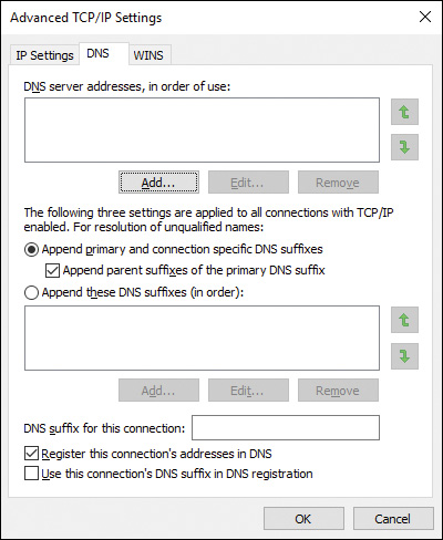
Figure 6-3 DNS Tab of Advanced TCP/IP Settings Enabling You to Configure Additional DNS Settings to Be Used by Your Network Connection
Step 8. To specify additional DNS servers, click the Add button under the DNS server addresses section, type the IP address to the additional DNS server, and then click Add.
Step 9. The lower section of the DNS tab applies to the fully qualified domain name (FQDN) of resources. Users sometimes use a simple name for a computer or printer. This section enables you to configure the last portion of the domain name that will be appended to the simple name to create an FQDN. For example, if you have configured mydomain.local and jubilee.local in this box, and the user typed in server, the computer automatically attempts to contact server.mydomain.local. If that fails, the computer then attempts to contact server.jubilee.local. Click the Append These DNS Suffixes (in Order) option. Then click the Add button to configure the DNS suffixes.
Step 10. For a DNS server that provides Dynamic DNS, and when you want to share files or printers from your computer, you should register your computer’s DNS name and IP address in the DNS database. To do so, select the Register This Connection’s Addresses in DNS check box.
Step 11. Click the WINS tab. WINS provides resolution for NetBIOS names to IP addresses on Windows networks. If you use legacy networks, or have applications that require NetBIOS names, you should configure the address for a WINS server on the network.
Tip
You can also use the netsh.exe tool to configure IPv4 from the command line. This tool enables you to perform almost any network configuration action from the command prompt. For example, the command netsh interface ip set address “Local Area connection” static 192.168.0.2 255.255.255.0 192.168.0.1 configures the computer’s local area connection with the static IP address 192.168.0.2, subnet mask 255.255.255.0, and default gateway 192.168.0.1. For more information, refer to “Netsh Overview” at http://technet.microsoft.com/en-us/library/cc732279(WS.10).aspx.
Configuring TCP/IPv6 Name Resolution
You can configure name resolution with IPv6 in much the same way as done with IPv4, as the following steps demonstrate:
Step 1. Use the procedure outlined in the previous section to access the Internet Protocol Version 6 (TCP/IPv6) Properties dialog box.
Step 2. If your network is configured to use DHCP to automatically configure client computers with the address of the DNS server, you need only ensure that the Obtain DNS Server Address Automatically option is selected.
Step 3. If your network is not configured with DHCP, click the Use the Following DNS Server Addresses option and type the IPv6 address for at least one DNS server.
Step 4. Click Advanced to bring up the Advanced TCP/IP Settings dialog box previously shown in Figure 6-2 (settings for IPv6 will not have a WINS tab).
Step 5. Click the DNS tab to display the available DNS settings, which are identical to those found in the DNS tab for IPv4 described previously and shown in Figure 6-3. Click Add under the DNS Server Addresses section to add the IPv6 addresses of additional DNS servers, as required.
Step 6. To specify additional DNS servers, click the Add button under the DNS server addresses section, type the IPv6 address to the additional DNS server, and then click Add.
Step 7. As was the case with IPv4, if you need additional DNS suffixes to specify the FQDN of resources, click the Append These DNS Suffixes (in Order) option. Then click the Add button to configure the DNS suffixes.
Step 8. For a DNS server that provides Dynamic DNS, and when you want to share files or printers from your computer, you should register your computer’s DNS name and IP address in the DNS database. To do so, select the Register This Connection’s Addresses in DNS check box.
Step 9. Click OK until you’re returned to the Local Area Connection Properties dialog box.
Note
DNS name resolution in IPv6 operates in a manner similar to that previously mentioned for IPv4, except that DNS servers use AAAA resource records to hold the hostname to IPv6 address mapping, as opposed to A records used for IPv4 mapping.
Disabling IPv6
You cannot remove IPv6 from a Windows 10 computer. However, you can disable IPv6 on a specific connection. From the Ethernet Properties dialog box, clear the check box beside Internet Protocol Version 6 (TCP/IPv6) and then click OK. You can do this selectively for each network connection on your computer.
Note
You can also selectively disable IPv6 components. This is a more complex procedure that involves editing the Registry and is beyond the scope of this book. For more details, refer to “How to Disable IPv6 or Its Components in Windows” at http://support.microsoft.com/kb/929852.
Connecting to a Wired Network
Windows 10 simplifies the process of connecting to diverse types of networks, including wired and wireless networks. In this section, you learn about connecting your computer to wired networks. Chapter 8, “Windows 10 Data Security,” extends this discussion to include methods used for connecting to and securing wireless networks. In Windows 10, you can quickly obtain a view of available network devices by opening File Explorer Network. The Network Explorer applet displays this information, as shown in Figure 6-4.
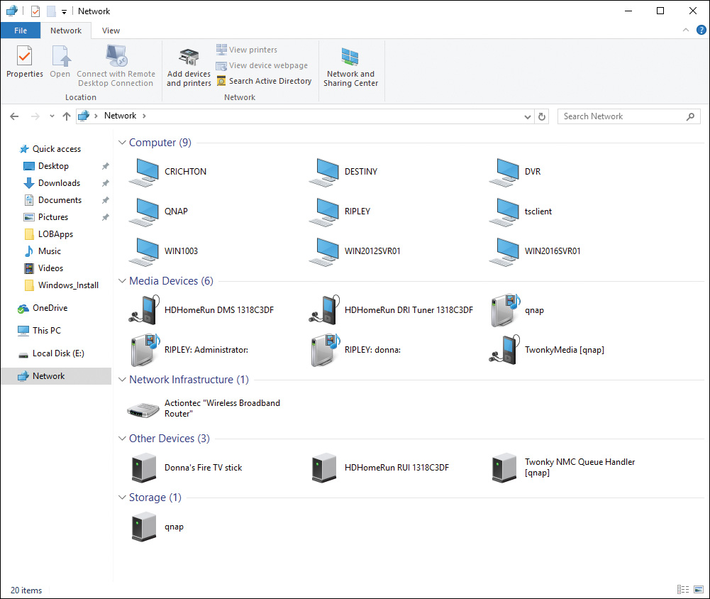
Figure 6-4 Network App in Windows 10 Displaying Several Types of Networked Devices
The Network and Sharing Center
First introduced in Windows Vista and continued in Windows 7, Windows 8.1, and Windows 10, the Network and Sharing Center, shown in Figure 6-5, brings all networking tasks together in a single convenient location. You can configure connections to other computers and networks; share folders, printers, and media; view devices on your network; set up and manage network connections; and troubleshoot problems from this location.
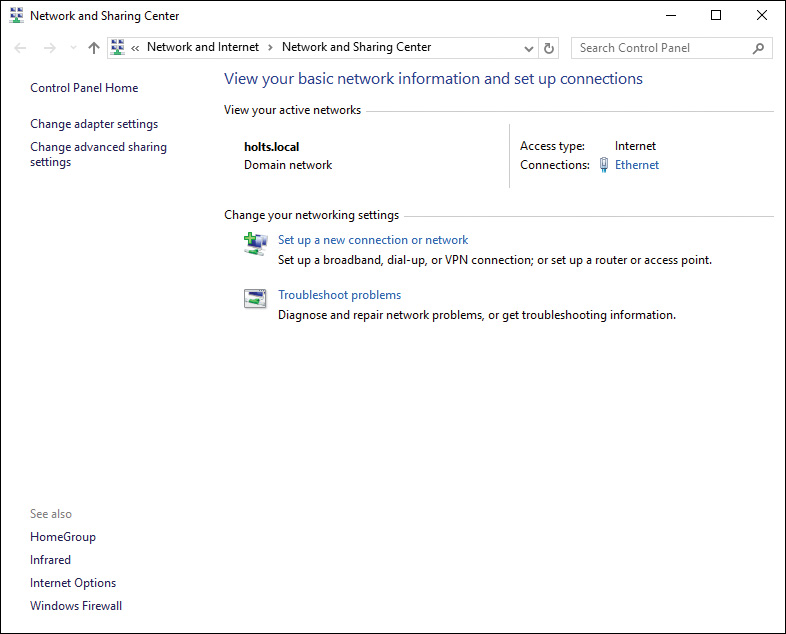
Figure 6-5 Network and Sharing Center Providing a Centralized Location for Configuring Network Properties
You can open the Network and Sharing Center by using any of the following methods:
![]() If you have the Network window open as previously shown in Figure 6-4, click the icon for the Network and Sharing Center on the menu bar.
If you have the Network window open as previously shown in Figure 6-4, click the icon for the Network and Sharing Center on the menu bar.
![]() Access the Search box or Cortana and type network. From the icons displayed, click Network and Sharing Center.
Access the Search box or Cortana and type network. From the icons displayed, click Network and Sharing Center.
![]() Open the Network icon from Action Center and click Network Settings. On the Settings page, click the Network and Sharing Center link.
Open the Network icon from Action Center and click Network Settings. On the Settings page, click the Network and Sharing Center link.
The Network and Sharing Center enables you to configure connections to other computers and networks; share folders, printers, and media; view devices on your network; set up and manage network connections; and troubleshoot connectivity problems.
Using the Network and Sharing Center to Set Up a TCP/IPv4 Connection
You can configure TCP/IP version 4 on a Windows 10 computer either manually or dynamically. The default method is to dynamically configure TCP/IP. If the infrastructure includes DHCP services that deliver IP addresses to network computers, a Windows 10 computer can connect upon logon with the default configuration of the network adapter. However, if you need to apply a static IPv4 address and other parameters, your only option is to manually configure the network adapter. Manually configuring a single computer is time-consuming and error-prone. Multiply that by hundreds of computers and you can see why dynamic configuration has become so popular. Use the following procedure to configure a network adapter with a static IPv4 address:
Step 1. Open the Network and Sharing Center by any of the methods described in the previous section.
Step 2. From the Tasks list on the left side of the Network and Sharing Center, click Change Adapter Settings. This opens the Network Connections dialog box, as shown in Figure 6-6.
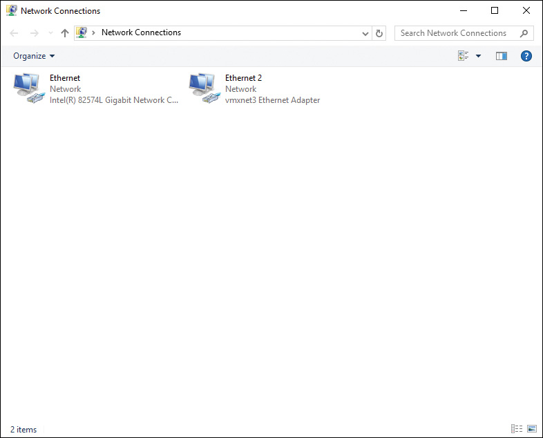
Figure 6-6 Network Connections Displaying the Network Connections Configured for Your Computer
Step 3. Right-click the connection that represents the adapter you are going to configure and select Properties. If you receive a User Account Control (UAC) prompt, click Yes. The Ethernet Properties dialog box opens, as shown in Figure 6-7.
Step 4. Click to select Internet Protocol Version 4 (TCP/IPv4). (You might need to scroll through other services to reach this item.) Click Properties. The Internet Protocol Version 4 (TCP/IPv4) Properties dialog opens, as shown previously in Figure 6-1.
Step 5. To use DHCP services, you should make certain that Obtain an IP Address Automatically is selected, and if the DHCP server provides extended information—including the DNS server information—you would also select Obtain DNS Server Address Automatically. To manually configure the IP address, you should click Use the Following IP Address.
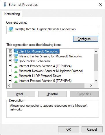
Figure 6-7 Network Adapter Is Considered a Network Connection
Step 6. In the IP address box, type the address that will function on the current network segment. For example, if the network segment uses a Class C address 192.168.1.0 with a subnet mask of 255.255.255.0, and you’ve already used 192.168.1.1 and 192.168.1.2, you could select any node address from 3 through 254 (255 is used for broadcasts), in which case you would type 192.168.1.3.
Step 7. In the Subnet Mask box, type the subnet mask. In this case, it would be 255.255.255.0.
Step 8. In the Default gateway box, type the IP address that is assigned to the router interface on your current segment that leads to the main network or the public network. In this case, the IP address of the router on your segment is 192.168.1.1, and the IP address of the router’s other interface is 12.88.54.179. In the Default Gateway box, you would type 192.168.1.1.
Step 9. To configure an alternate IP address on a computer configured to use DHCP, click the Alternate Configuration tab to display the dialog box shown in Figure 6-8. Click User Configured and then enter the required IP address, subnet mask, default gateway, and DNS and WINS server information. Then click OK. This is useful if your computer must connect to different networks, such as work and home.
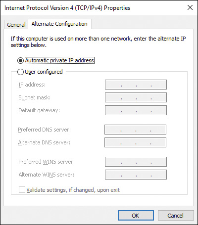
Figure 6-8 TCP/IPv4 Alternate Configuration Tab
Step 10. Click the Advanced button. The Advanced TCP/IP Settings dialog box opens, as shown previously in Figure 6-2.
Step 11. If you require more than one IP address for a computer, such as for hosting two different websites, you can configure the additional IP addresses in this dialog box by clicking the Add button under IP addresses. You cannot configure any additional IP addresses if you are using DHCP.
Step 12. If your network segment is connected to more than one router leading to the main or outside networks, you can configure these gateway addresses in the Default Gateways section by clicking the Add button.
Step 13. When finished, click OK until you’re returned to the Network Connections dialog box.
Tip
Many hardware routers, including those used when connecting home networks to high-speed Internet connections, include DHCP functionality. If you are using one of these, leave the defaults selected in step 5 of the preceding procedure.
Implementing APIPA
The Automatic Private Internet Protocol Addressing (APIPA) system provides an alternate configuration to DHCP for automatic IP addressing in small networks. When a computer uses APIPA, Windows 10 assigns itself an IP address and then verifies that it is unique on the local network. To work effectively, APIPA is useful only on a small local area network (LAN) or as a backup to DHCP.
When a Windows 10 computer begins its network configuration, it performs the following procedures:
Step 1. It checks to see whether there is a manually configured (or static) IP address.
Step 2. If there is none, it contacts a DHCP server with a query for configuration settings. A response from a DHCP server leases—or validates the lease of—an IP address, subnet mask, and extended IP information, such as DNS server, default gateway, and so on.
Step 3. If there is no DHCP server response within 6 seconds, Windows 10 looks to see whether an alternate configuration has been applied by the administrator.
Step 4. If there is no alternate configuration, Windows 10 uses APIPA to define an IP address unique on the LAN.
APIPA defines its IP addresses in the range of 169.254.0.1 to 169.254.255.254. The subnet mask on these addresses is configured as 255.255.0.0. You do have administrative control over APIPA. When Windows 10 selects an address from this range, it performs a duplicate address detection process to ensure that the IP address it has selected is not already being used, while continuing to query for a DHCP server in the background. If the address is found to be in use, Windows 10 selects another address. The random IP selection occurs recursively until an unused IP address is selected, a DHCP server is discovered, or the process has taken place 10 times.
Connecting to a TCP/IP Version 6 Network
You can let IPv6 configure itself automatically with a link-local address described previously in Table 6-5. You can also configure IPv6 to use an existing DHCP server or manually configure an IPv6 address as required. Configuration of IPv6 addresses is similar to the procedure used with configuration of IPv4 addresses, as the following procedure shows:
Step 1. Open the Network and Sharing Center by any of the methods previously described.
Step 2. From the Tasks list on the left side of the Network and Sharing Center, click Change Adapter Settings. This opens the Network Connections dialog box, as previously shown in Figure 6-6.
Step 3. Right-click the connection that represents the adapter you are going to configure and select Properties. If you receive a UAC prompt, click Yes.
Step 4. Click to select Internet Protocol Version 6 (TCP/IPv6). (You might need to scroll through other services to reach this item.) Click Properties. The Internet Protocol Version 6 (TCP/IPv6) Properties dialog opens, as shown in Figure 6-9.

Figure 6-9 Internet Protocol Version 6 (TCP/IPv6) Properties Lets You Define Manual or Dynamic IPv6 Address Information
Step 5. To use DHCP, ensure that the Obtain an IPv6 Address Automatically radio button is selected. If the DHCP server provides DNS server information, ensure that the Obtain DNS Server Address Automatically radio button is also selected. You can also select these options to configure IPv6 automatically with a link-local address using the address prefix fe80::/64 previously described in Table 6-5.
Step 6. To manually configure an IPv6 address, select Use the Following IPv6 Address. Then type the IPv6 address, subnet prefix length, and default gateway in the text boxes provided. For unicast IPv6 addresses, you should set the prefix length to its default value of 64.
Step 7. To manually configure DNS server addresses, select Use the Following DNS Server Addresses. Then type the IPv6 addresses of the preferred and alternate DNS server in the text boxes provided.
Step 8. Click Advanced to display the Advanced TCP/IP Settings dialog box shown in Figure 6-10.
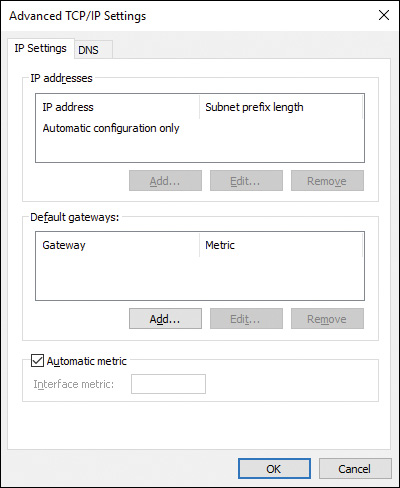
Figure 6-10 Advanced TCP/IP Settings Allowing You to Control Granular IPv6 Addressing Options
Step 9. As with IPv4, you can configure additional IP addresses if you are not using DHCP. Click Add and type the required IP address into the dialog box that appears.
Step 10. As with IPv4, if your network segment is connected to more than one router, configure additional gateway addresses in the Default Gateways section by clicking the Add button.
Step 11. When finished, click OK until you’re returned to the Network Connections dialog box.
Tip
You can also use the netsh.exe tool with the interface IPv6 subcommand to configure IPv6 from the command line. For example, netsh interface IPv6 set address “local area connection 2” fec0:0:0:ffee::3 sets the IPv6 address of the second local area connection to the specified address. For more information, refer to “IPv6 Configuration Information with the Netsh.exe Tool” at http://technet.microsoft.com/en-us/library/bb726952.aspx#EBAA.
Configuring Network Locations
A network location defines a set of conditions contained within a network profile that govern whether computers on the network can view your computer and resources such as files, folders, and printers to which it is connected. Microsoft makes available network profiles corresponding to private and public network locations that are configured by default to enhance the security of your computer when connected to a public network such as a Wi-Fi hotspot.
Setting Up New Network Connections
The Network and Sharing Center enables you to set up new networking connections. Click Set Up a New Connection or Network (refer to Figure 6-5) to display the Set Up a Connection or Network Wizard shown in Figure 6-11. (Note that this dialog box may not display all these options; the options vary according to the networking hardware attached to your computer.)
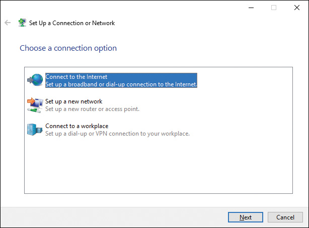
Figure 6-11 Set Up a Connection or Network Wizard Offering Several Options for Connecting Your Computer to Networks
Select from the following options, and then click Next:
![]() Connect to the Internet: Detects any type of device (such as a cable or DSL broadband connection) and enables you to enter the username and password provided by your ISP, as shown in Figure 6-12. You can also enter a connection name that helps you to identify this connection later. If you want to enable other users on the computer to connect, select Allow Other People to Use This Connection.
Connect to the Internet: Detects any type of device (such as a cable or DSL broadband connection) and enables you to enter the username and password provided by your ISP, as shown in Figure 6-12. You can also enter a connection name that helps you to identify this connection later. If you want to enable other users on the computer to connect, select Allow Other People to Use This Connection.
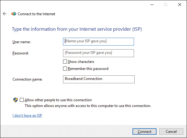
Figure 6-12 Entering Username and Password to Connect to the Internet
![]() Set Up a New Network: Searches for the wireless router or access point you want to configure and then attempts to configure this device for you. Although the wizard states that it might take up to 90 seconds to display unconfigured devices, this process can take considerably longer.
Set Up a New Network: Searches for the wireless router or access point you want to configure and then attempts to configure this device for you. Although the wizard states that it might take up to 90 seconds to display unconfigured devices, this process can take considerably longer.
![]() Manually Connect to a Wireless Network: Enables you to enter the wireless network information required for connecting to the network. We discuss wireless networking in Chapter 11, “Configuring and Securing Mobile Devices.”
Manually Connect to a Wireless Network: Enables you to enter the wireless network information required for connecting to the network. We discuss wireless networking in Chapter 11, “Configuring and Securing Mobile Devices.”
![]() Connect to a Workplace: Enables you to connect by means of a virtual private network (VPN) connection across the Internet or to dial directly to the workplace network using a phone line without using the Internet. We discuss VPN connections in Chapter 15, “Configuring Remote Access.”
Connect to a Workplace: Enables you to connect by means of a virtual private network (VPN) connection across the Internet or to dial directly to the workplace network using a phone line without using the Internet. We discuss VPN connections in Chapter 15, “Configuring Remote Access.”
![]() Set Up a Wireless Ad Hoc (Computer-to-Computer) Network: Enables you to connect directly to another wireless-enabled computer without the need for a wireless access point. If you do set up a connection of this type, you are disconnected from other wireless networks.
Set Up a Wireless Ad Hoc (Computer-to-Computer) Network: Enables you to connect directly to another wireless-enabled computer without the need for a wireless access point. If you do set up a connection of this type, you are disconnected from other wireless networks.
Connecting to Existing Networks
You can manage your network connections using the Network & Internet settings page. From the Action Center, select the Network icon and then click Network Settings. This displays the settings for your current connections, as shown in Figure 6-13.
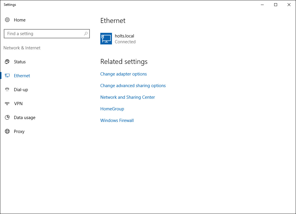
Figure 6-13 Network & Internet Settings Page to Manage Your Connections
When you open this settings page, or click the Network icon in Action Center, you are informed which network you are connected to and which networks are available. Select a desired network and then click Connect. To disconnect from a network, select it and then click Disconnect.
These operations apply only to dial-up and Wi-Fi connections. To disconnect from a wired or Ethernet connection, access the Network Connections screen, select the device, and then select Disable This Network Device.
Setting Up Network Sharing and Discovery
You can access additional sharing and network discovery options from the Network & Internet Settings page. Click the Change Advanced Sharing Settings, found in the Related Settings section of the device you are connected to. As shown in Figure 6-14, the Advanced Sharing Settings dialog box enables you to configure the additional networking options provided in the list that follows. (Available options depend on the profile you’re using, either Private, Guest or Public, Domain, or All Networks.)

Figure 6-14 Advanced Sharing Settings Enabling You to Configure Sharing Options for Different Network Profiles
![]() Network Discovery: Enables your computers to see other network computers and devices and enables these machines to access your computer. To ensure that all network devices are detected and configured, ensure that the Turn On Automatic Setup of Network Connected Devices option is selected. (This option is selected by default.)
Network Discovery: Enables your computers to see other network computers and devices and enables these machines to access your computer. To ensure that all network devices are detected and configured, ensure that the Turn On Automatic Setup of Network Connected Devices option is selected. (This option is selected by default.)
![]() File and Printer Sharing and Public Folder Sharing: These options enable you to share files and printers on your computer that will be visible to other computers on the network. We discuss these options in Chapter 14, “Configuring File and Folder Access.”
File and Printer Sharing and Public Folder Sharing: These options enable you to share files and printers on your computer that will be visible to other computers on the network. We discuss these options in Chapter 14, “Configuring File and Folder Access.”
![]() Media Streaming: Enables machines on the network to access shared photos, videos, and music stored on your computer. Enables your computer to locate these types of shared information on other network computers.
Media Streaming: Enables machines on the network to access shared photos, videos, and music stored on your computer. Enables your computer to locate these types of shared information on other network computers.
![]() File Sharing Connections: Enables you to select the strength of encryption used for protecting file sharing connections with other machines on the network. By default, file sharing is enabled for machines that use 40- or 56-bit encryption, but you can choose to increase security by selecting 128-bit encryption. However, devices that do not support 128-bit encryption will be unable to access resources on your computer.
File Sharing Connections: Enables you to select the strength of encryption used for protecting file sharing connections with other machines on the network. By default, file sharing is enabled for machines that use 40- or 56-bit encryption, but you can choose to increase security by selecting 128-bit encryption. However, devices that do not support 128-bit encryption will be unable to access resources on your computer.
![]() Password Protected Sharing: Requires users attempting to access shared resources on your computer to have a user account with a password. Turn this option off if you want to enable users without a password to have access.
Password Protected Sharing: Requires users attempting to access shared resources on your computer to have a user account with a password. Turn this option off if you want to enable users without a password to have access.
![]() HomeGroup Connections: Enables you to determine whether Windows will utilize simple homegroup-based sharing or use the classic type of file sharing model employed by Windows versions prior to Windows 7. More information is provided in Chapter 14.
HomeGroup Connections: Enables you to determine whether Windows will utilize simple homegroup-based sharing or use the classic type of file sharing model employed by Windows versions prior to Windows 7. More information is provided in Chapter 14.
Tip
You can configure sharing options for up to four network profiles:
1. Private
2. Guest or Public
3. Domain (on a domain-joined computer)
4. All Networks
This enables you to maintain these network profiles when switching between different network types, so that when you connect to a public network, you can select the All Networks option to apply more restrictive sharing options automatically.
Using Internet Connection Sharing to Share Your Internet Connection
Quite often, it is not feasible for a small office or a home user to install a high-speed dedicated link to the Internet (such as a T1 line) or have each computer dial up to an ISP. Nowadays, home users can utilize a dedicated broadband link, such as a reasonably priced cable or DSL link.
One of the growing trends for small office or home networks is to share an Internet connection with all the members of the network. Windows 10 contains a feature called Internet Connection Sharing (ICS), which enables a small office or home network to use one computer on the network as the router to the Internet.
Windows 10’s ICS components consist of the following:
![]() Auto-dial: A method of establishing the Internet connection when attempting to access Internet resources on a computer that does not host the Internet connection.
Auto-dial: A method of establishing the Internet connection when attempting to access Internet resources on a computer that does not host the Internet connection.
![]() DHCP Allocator: A simplified DHCP service that assigns IP addresses from the address range of 192.168.0.2–192.168.0.254, with a mask of 255.255.255.0 and default gateway of 192.168.0.1.
DHCP Allocator: A simplified DHCP service that assigns IP addresses from the address range of 192.168.0.2–192.168.0.254, with a mask of 255.255.255.0 and default gateway of 192.168.0.1.
![]() DNS Proxy: Forwards DNS requests to the DNS server and forwards the DNS replies back to the clients.
DNS Proxy: Forwards DNS requests to the DNS server and forwards the DNS replies back to the clients.
![]() Network Address Translation (NAT): Maps the range of private Class C IPv4 addresses (192.168.0.1–192.168.0.254) to the public IP address, which is assigned by the ISP. NAT is a specification in TCP/IP that tracks the source private IP addresses and outbound public IP address(es), reformatting the IP address data in the header dynamically so that the source requests reach the public resources, and the public servers can reply to the correct source-requesting clients.
Network Address Translation (NAT): Maps the range of private Class C IPv4 addresses (192.168.0.1–192.168.0.254) to the public IP address, which is assigned by the ISP. NAT is a specification in TCP/IP that tracks the source private IP addresses and outbound public IP address(es), reformatting the IP address data in the header dynamically so that the source requests reach the public resources, and the public servers can reply to the correct source-requesting clients.
Note
NAT runs on a server or router and is capable of translating multiple external IP addresses to internal private IP addresses used on client computers. The NAT server/router can also be configured to provide DHCP services to the client computers. For more information on NAT, refer to the “Network Address Translation (NAT) FAQ” at www.cisco.com/c/en/us/support/docs/ip/network-address-translation-nat/26704-nat-faq-00.xhtml.
You can use ICS to share any type of Internet connection, although it must be a connection that is enabled for all users on the PC dial-up for sharing to be effective. To enable ICS, you need to make sure that the Internet-connected computer has been configured with connections for a modem and a network adapter. If you are using broadband, you need two network adapters: one to connect to the broadband device for the Internet and the other to connect to the network. Use the following procedure at the computer that is connected to the Internet to set up ICS:
Step 1. From the Network and Sharing Center, click Change Adapter Settings, found on the left side. This opens the Network Connections dialog box previously shown in Figure 6-6.
Step 2. Right-click the connection you want to share and choose Properties. If you receive a UAC prompt, click Yes.
Step 3. Select the Sharing tab to receive the dialog box shown in Figure 6-15.
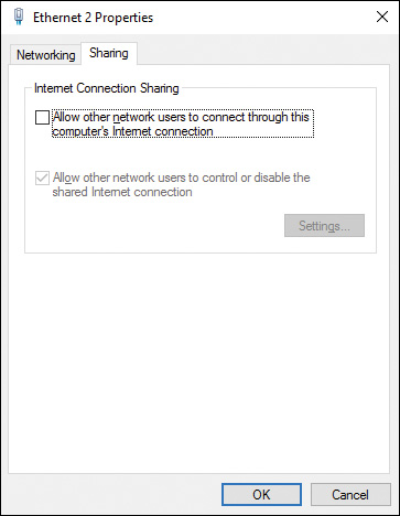
Figure 6-15 Sharing Tab of the Ethernet Properties Dialog Box Enabling You to Share Your Computer’s Internet Connection with Other Computers on the Network
Step 4. Select the check box labeled Allow Other Network Users to Connect Through This Computer’s Internet Connection.
Step 5. If desired, select the check box labeled Allow Other Network Users to Control or Disable the Shared Internet Connection.
Caution
Before you configure ICS, you should ensure that no computers are currently assigned an IP address of 192.168.0.1, because the network adapter on the ICS computer is automatically assigned that address when ICS is configured.
After you have shared your connection, you need to configure the other computers to use this connection, as follows:
Step 1. In the bottom-left corner of the Network and Sharing Center, click Internet Options to display the Internet Properties dialog box.
Step 2. Select the Connections tab.
Step 3. Click the LAN Settings command button.
Step 4. On the Local Area Network (LAN) Settings dialog box shown in Figure 6-16, clear the check boxes for Automatically Detect Settings, Use Automatic Configuration Script, and Use a Proxy Server for Your LAN. Then click OK.

Figure 6-16 Local Area Network (LAN) Settings Dialog Box with All Check Boxes Cleared
Step 5. From the Network Connections dialog box previously shown in Figure 6-6, right-click the shared connection and choose Properties.
Step 6. Click Internet Protocol Version 4 (TCP/IPv4) or Internet Protocol Version 6 (TCP/IPv6) and then click Properties.
Step 7. On the Properties dialog box, select Obtain an IP Address Automatically or Obtain an IPv6 Address Automatically.
If you have problems with ICS, you should open Event Viewer and check out the System log for any errors related to ICS. In addition, you can view the NSW.LOG file to look for errors. The following are several additional suggestions in case users are unable to access the Internet from the client computers:
![]() Check the configuration of the client Internet browser. We mentioned client configuration earlier in this section.
Check the configuration of the client Internet browser. We mentioned client configuration earlier in this section.
![]() Ensure that the client can connect to the host computer. Check the connection by typing ping 192.168.0.1. If this ping is unsuccessful, check the physical network connections.
Ensure that the client can connect to the host computer. Check the connection by typing ping 192.168.0.1. If this ping is unsuccessful, check the physical network connections.
![]() Use ipconfig to check the client computer’s IP configuration. Ensure that the client has an IP address on the proper subnet and that the default gateway is set to 192.168.0.1.
Use ipconfig to check the client computer’s IP configuration. Ensure that the client has an IP address on the proper subnet and that the default gateway is set to 192.168.0.1.
Note
For more information on ICS, including its use with IPv6, refer to “Using Wireless Hosted Network and Internet Connection Sharing” at https://msdn.microsoft.com/en-us/library/windows/desktop/dd815252(v=vs.85).aspx. The article discusses Windows 7 and Windows 8, but the functionality is the same for Windows 10 and Windows Server 2016.
Configuring Network Settings
In the previous section, you learned about TCP/IP network connections, working with network adapters, configuring protocols, and connection-level settings for Windows networks. In this section, you move on to learning about connecting to wireless networks, configuring your wireless network preferences, and about group policies for managing network configuration settings.
You should also know some techniques for troubleshooting network connections and dealing with network issues, and you will learn about some tools and techniques for doing that in this section.
Connecting to Wireless Networks
The recent advances in wireless networking technology have enabled individuals to connect to networks from virtually any place a wireless access point is available. Many offices are taking advantage of the ease of setup of wireless local area networks (WLANs), which allow for mobility and portability of computers and other devices located within the office. Public access points in locations such as restaurants and airports permit users to send and receive data from many places that would have been unthought of not too many years ago. Along with this convenience comes an increased chance of unauthorized access to the networks and the data they contain.
Wireless networks are easy to install and use, and they have gained tremendous popularity for small home and office networks. Security is still not perfected for wireless networks, so large corporations have been slower to implement large wireless networks. Windows 10 supports the 802.11 protocols for wireless LANs and is capable of transparently moving between multiple wireless access points (WAPs), changing to a new IP subnet, and remaining connected to the network. Each time the IP subnet changes, the user is reauthenticated. In Windows 10, you can configure wireless networking in the Network and Sharing Center. This enables you to connect to wireless networks, configure an ad hoc connection or the use of a WAP, and manage your wireless networks.
Windows 10 provides similar wireless technologies to those of Windows 7 and 8.1, improving upon wireless support for Windows so that wireless networking is as well integrated with the operating system as normal networking. Consequently, wireless network reliability, stability, and security are considerably enhanced over older versions of the Windows operating system. The following are some of the more important security improvements in wireless networking available in recent Windows versions:
![]() Windows 10 minimizes the amount of private information, such as the service set identifier (SSID) that is broadcast before connecting to a wireless network.
Windows 10 minimizes the amount of private information, such as the service set identifier (SSID) that is broadcast before connecting to a wireless network.
![]() When users connect to an unencrypted public network (such as an airport or restaurant Wi-Fi hotspot), users are warned of the risks so that they can limit their activities accordingly.
When users connect to an unencrypted public network (such as an airport or restaurant Wi-Fi hotspot), users are warned of the risks so that they can limit their activities accordingly.
![]() Windows 10 supports a complete range of wireless security protocols, from Wired Equivalent Privacy (WEP) to Wi-Fi Protected Access (WPA and WPA2), Protected Extensible Authentication Protocol (PEAP), and its combination with Microsoft Challenge Handshake Authentication Protocol version 2 (MS-CHAPv2) and Extensible Authentication Protocol Transport Layer Security (EAP-TLS).
Windows 10 supports a complete range of wireless security protocols, from Wired Equivalent Privacy (WEP) to Wi-Fi Protected Access (WPA and WPA2), Protected Extensible Authentication Protocol (PEAP), and its combination with Microsoft Challenge Handshake Authentication Protocol version 2 (MS-CHAPv2) and Extensible Authentication Protocol Transport Layer Security (EAP-TLS).
![]() Windows 10 uses WPA2-Personal for maximum security when communicating by means of an ad hoc wireless network (direct communication with another wireless computer without use of an access point). This helps to protect against common vulnerabilities associated with such unprotected networks.
Windows 10 uses WPA2-Personal for maximum security when communicating by means of an ad hoc wireless network (direct communication with another wireless computer without use of an access point). This helps to protect against common vulnerabilities associated with such unprotected networks.
![]() On an Active Directory Domain Services (AD DS) network, administrators can use Group Policy settings to configure Single Sign On (SSO) profiles that facilitate wireless domain logon. The 802.1x authentication precedes the domain logon, and users are prompted for wireless credentials only if absolutely necessary. The wireless connection is therefore in place before the domain logon proceeds.
On an Active Directory Domain Services (AD DS) network, administrators can use Group Policy settings to configure Single Sign On (SSO) profiles that facilitate wireless domain logon. The 802.1x authentication precedes the domain logon, and users are prompted for wireless credentials only if absolutely necessary. The wireless connection is therefore in place before the domain logon proceeds.
Wireless Networking Protocols
Table 6-6 describes four wireless networking protocols available to Windows 10.
Table 6-6 Characteristics of Wireless Networking Protocols
Protocol |
Transmission Speed |
Frequency Used |
Comments |
802.11b |
11 Mbps |
2.4 GHz |
The 2.4 GHz frequency is the same as that which is used by many appliances such as cordless phones and microwave ovens; this can cause interference. This technology also is limited in that it supports fewer simultaneous users than the other protocols. |
802.11a |
54 Mbps |
5 GHz |
While reducing interference from other appliances, this technology has a shorter signal range and is not compatible with network adapters, routers, and WAPs using the 802.11b protocol. However, some devices are equipped to support either 802.11a or 802.11b. |
802.11g |
54 Mbps |
2.4 GHz |
You can have 802.11b and 802.11g devices operating together on the same network. This standard was created specifically for backward compatibility with the 802.11b standard. The signal range is better than that of 802.11a, but this technology suffers from the same interference problems as 802.11a. |
802.11n |
Up to 150–600 Mbps depending on the number of data streams |
2.4 or 5 GHz |
This technology is compatible with devices using the older protocols at the same frequency. It also has the best signal range and is most resistant to interference, though it can have the same problems as 802.11b if using the 2.4 GHz frequency. |
802.11ac |
Up to 1.3 Gbps |
5 GHz |
New technology that improves upon 802.11n by offering faster speeds and improved scalability. Computer and device manufacturers are beginning to produce compatible units, with devices expected to be available by 2015. |
Note
For more information on 802.11ac and the improvements it offers, refer to “802.11ac: The Fifth Generation of Wi-Fi Technical White Paper” at www.cisco.com/en/US/prod/collateral/wireless/ps5678/ps11983/white_paper_c11-713103.xhtml.
Setting Up a Wireless Network Connection
Windows 10 provides a wizard that simplifies the process of setting up various types of network connections and connecting to wireless and other networks. Use the following procedure to set up a wireless network connection:
Step 1. Use one of the methods outlined earlier in this chapter to access the Network and Sharing Center.
Step 2. Click Set Up a New Connection or Network (refer to Figure 6-5) to start the wizard.
Step 3. Click Set Up a New Network and then click Next. You are informed that it might take up to 90 seconds for unconfigured network devices to be detected.
Step 4. When the wizard detects the required wireless router or WAP, select it and click Next.
Step 5. On the Give Your Network a Name page, type the network name and security key used by the required router or WAP. Choose the required security level and encryption type (more about these later in this chapter) and then click Next.
Step 6. The wizard configures your network. When done, click Finish.
You can connect to a network that you have not previously set up by following these steps:
Step 1. From the Network and Sharing Center, click Set Up a New Connection or Network.
Step 2. Click Manually Connect to a Wireless Network, and then click Next.
Step 3. The wizard displays the Manually Connect to a Wireless Network page shown in Figure 6-17. Enter the following information and then click Next.
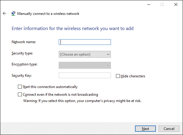
Figure 6-17 Manually Connect to a Wireless Network Page Enabling You to Enter Information Required for Connecting to a Wireless Network
![]() Network Name: The name (SSID) of the wireless network you are connecting to.
Network Name: The name (SSID) of the wireless network you are connecting to.
![]() Security Type: Authentication method to be used in connecting to the wireless network. Table 6-7 lists the available security types.
Security Type: Authentication method to be used in connecting to the wireless network. Table 6-7 lists the available security types.
![]() Encryption Type: The encryption type will be selected for you depending on the Security type. The options are None (for No authentication), WEP (for WEP connections or 802.1x), or AES for WPA2-Personal or WPA2-Enterprise (see Table 6-7).
Encryption Type: The encryption type will be selected for you depending on the Security type. The options are None (for No authentication), WEP (for WEP connections or 802.1x), or AES for WPA2-Personal or WPA2-Enterprise (see Table 6-7).
![]() Security Key: Enter the security key required by the security type selected (the WEP key for the WEP security type), or the WPA2 preshared key (for the WPA2-Personal security type). Clear the Hide Characters check box to view the information typed here.
Security Key: Enter the security key required by the security type selected (the WEP key for the WEP security type), or the WPA2 preshared key (for the WPA2-Personal security type). Clear the Hide Characters check box to view the information typed here.
![]() Start This Connection Automatically: When selected, Windows 10 automatically connects to the network when you log on. When cleared, you must use the Connect to a Network option from the Network and Sharing Center to connect to the network.
Start This Connection Automatically: When selected, Windows 10 automatically connects to the network when you log on. When cleared, you must use the Connect to a Network option from the Network and Sharing Center to connect to the network.
![]() Connect Even if the Network Is Not Broadcasting: Specifies whether Windows will attempt to connect even if the network is not broadcasting its name. This can be a security risk because Windows 10 sends Probe Request frames to locate the network, which unauthorized users can use to determine the network name. Consequently, this check box is not selected by default.
Connect Even if the Network Is Not Broadcasting: Specifies whether Windows will attempt to connect even if the network is not broadcasting its name. This can be a security risk because Windows 10 sends Probe Request frames to locate the network, which unauthorized users can use to determine the network name. Consequently, this check box is not selected by default.
Step 4. The wizard informs you that it has successfully added the network you specified. Click the link specified to connect to the network, or click the Close button to finish the wizard without connecting.
Table 6-7 Available Wireless Security Types
Security Type |
Description |
Available Encryption Types |
No authentication (open) |
Open system authentication with no encryption |
None |
WEP |
Open system authentication using WEP |
WEP |
WPA2-Personal |
Version 2 of WPA using a preshared passphrase or key |
AES (default) |
WPA2-Enterprise |
Version 2 of WPA using IEEE 802.1x authentication |
AES (default) |
802.1x |
IEEE 802.1x authentication using WEP (also known as dynamic WEP) |
WEP |
Note
WPA2-Enterprise security provides the highest level of wireless networking authentication security. It requires authentication in two phases: first, an open system authentication; second, authentication using EAP. It is suitable for domain-based authentication and on networks using a Remote Authentication Dial-In User Service (RADIUS) authentication server. In environments without the RADIUS server, you should use WPA2-Personal security.
The wireless network you configured is visible in the Network and Sharing Center, from which you can connect later if you have not chosen the Start This Connection Automatically option. You can also connect by selecting the Network icon from the Action Center.
Tip
On the 70-697 or 70-698 exams, you may be asked if you are required to type a security key or passphrase; you should select the WPA2-Personal option. If you are not required to type a security key or passphrase, you should select the WPA2-Enterprise option.
Managing Wireless Network Connections
After you have configured one or more wireless network connections, you can manage them from Settings. From the main Settings screen, select Network & Internet, select Wi-Fi from the menu, and then click the Manage Known Networks link. This displays the Settings screen as shown in Figure 6-18, with the networks you have configured in the list.
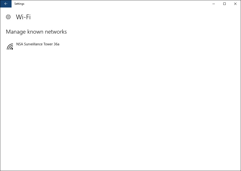
Figure 6-18 Connecting to Wireless Networks and Context Menu Options for Connected Network
To access the properties of a network connection, you can use the Network icon from Action Center. From there, click the wireless network icon and name. Click a network to connect to it, and to select or deselect the Connect Automatically option, as shown in Figure 6-19. This dialog is also displayed if you click the Show Available Networks link from the Wi-Fi settings page.
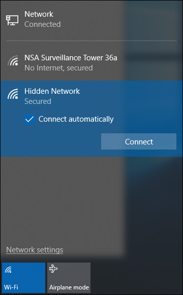
Figure 6-19 Wireless Networks and Connection Options
Several options are available for any network in range that you have connected to from the Manage Known Networks Settings page. If you select one of the networks from the Manage Known Networks page, Windows will display Properties and Forget buttons. Selecting Forget will clear out your settings for that Wi-Fi connection and automatically disconnect. When you select the Properties button of any wireless network, the following selections are available:
![]() Connect Automatically When in Range: This toggle tells Windows you want to connect to this Wi-Fi access point whenever it is available.
Connect Automatically When in Range: This toggle tells Windows you want to connect to this Wi-Fi access point whenever it is available.
![]() Make This PC Discoverable: For private or work networks, this option will turn sharing and discoverability on for the network. You should not use this option when connecting to open or public Wi-Fi access points.
Make This PC Discoverable: For private or work networks, this option will turn sharing and discoverability on for the network. You should not use this option when connecting to open or public Wi-Fi access points.
![]() Metered Connection: Turning this toggle on tells Windows that you have to pay for all the bandwidth you use on this connection. Windows will attempt to limit data usage on metered connections.
Metered Connection: Turning this toggle on tells Windows that you have to pay for all the bandwidth you use on this connection. Windows will attempt to limit data usage on metered connections.
![]() Copy: A list of detailed properties of the network connection is displayed on this screen, as shown in Figure 6-20. Clicking the Copy button places those details as text into the Clipboard, in case you need to save the Wi-Fi Properties to a file or email.
Copy: A list of detailed properties of the network connection is displayed on this screen, as shown in Figure 6-20. Clicking the Copy button places those details as text into the Clipboard, in case you need to save the Wi-Fi Properties to a file or email.

Figure 6-20 Detailed Properties of the Wi-Fi Connection Are Displayed and Can Be Copied to the Clipboard
Managing Preferred Wireless Networks
For Windows 10, Microsoft has simplified the user experience for working with wireless connections. Normally, Windows detects the type of wireless network, sets the security option, and manages profiles behind the scenes. Untrusted networks are set as public, and sharing is disabled. Private networks with security available are preferred, and Windows uses these networks before unsecured networks when available.
When you view available network connections, a small shield icon will appear on some network connections. This indicates to the user that the network is not secured, and Windows will treat the network as public. As described earlier, users can override the automated sharing selected and turn sharing on or off when connected to the network.
Whenever you connect to a new network and enable the Connect Automatically option, Windows places that network at the top of the priority list of preferred wireless networks.
Windows adjusts the priority of your list of preferred wireless networks based on the following criteria:
1. On connection to a new (undefined) wireless network, with Connect Automatically enabled, that network is added to the list, and Windows will connect to that network while it’s in range.
2. If you connect to another wireless network while in range of the first network, also setting the Connect Automatically option, Windows will prefer the second network over the first one.
3. For mobile broadband networks, manually connecting to a mobile broadband network when there is a Wi-Fi network in range will set the mobile broadband network as preferred only for that session. The next time the computer is in range of both networks, the wireless network will be preferred. Mobile broadband networks are typically metered, but this behavior persists even if the mobile broadband network is not specifically marked as metered.
4. To force Windows to prefer a mobile broadband network over Wi-Fi, click the Wi-Fi network in the list of networks, and then click Disconnect. Windows will not automatically connect to that Wi-Fi network.
Wireless Network Profiles
When you need to delete or make changes to the settings, you can usually do so from the Wi-Fi settings page of the connection as described in the previous section. However, some tasks require the use of the command prompt. For instance, managing the automatically created wireless profiles Windows 10 maintains for your wireless connections requires the use of the netsh command-line utility.
A wireless network profile is a set of wireless networks available to a given user on a Windows 10 computer. The profile contains information such as the SSID, the security settings as configured earlier in this chapter, and whether the network is an infrastructure or ad hoc network. There are two types of wireless network profiles:
![]() Per-User Profiles: These profiles apply to specific users of the computer and are connected when that user logs on to the computer. Note that these profiles can cause a loss of network connectivity when logging off or switching between users.
Per-User Profiles: These profiles apply to specific users of the computer and are connected when that user logs on to the computer. Note that these profiles can cause a loss of network connectivity when logging off or switching between users.
![]() All-User Profiles: These profiles apply to all users of the computer and are connected regardless of which user is logged on to the computer.
All-User Profiles: These profiles apply to all users of the computer and are connected regardless of which user is logged on to the computer.
To view the list of wireless profiles for the current user, open a command prompt, and type netsh wlan show profiles. To view the All-User profiles, run the same command from an administrative command prompt. The result will be similar to Figure 6-21.
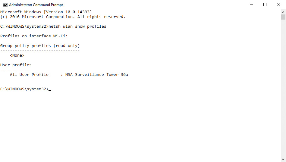
Figure 6-21 netsh wlan Commands Used to Manage Wireless Profiles
The netsh command lists all wireless network profiles, even if not in range, while the network list, as shown previously in Figure 6-19, includes only networks that are currently in range. You can delete a network profile using netsh commands, which is the same function as the Forget This Network option accessible from the Options menu.
Other important netsh commands for managing wireless networks and profiles are listed in Table 6-8. You should be aware that these commands will return profiles based on the user context. To manage all user profiles, use an administrative command prompt.
Table 6-8 Important netsh Wireless Networking Commands
Description |
|
netsh wlan show profiles |
Displays all wireless profiles on the computer |
netsh wlan show profile name=”<profilename>” key=clear |
Displays security key information for a profile named < profilename> that’s out of range |
netsh wlan delete profile name=”<profilename>” |
Deletes a profile that’s out of range |
netsh wlan set profileparametername=“<profilename>” connectionmode=manual |
Stops automatically connecting to a network that’s out of range |
Note
Many other netsh commands are available for managing networks. For more information, download the Network Shell (Netsh) Technical Reference from http://technet.microsoft.com/en-us/library/jj129394.aspx.
In addition to using the netsh command to manage wireless network profiles, you can also use Group Policy to deploy or maintain wireless network profiles. Whenever you connect to a wireless network, Windows creates a wireless profile entry in the Group Policies for the local computer. You will find the profiles under Computer ConfigurationPoliciesWindows SettingsSecurity SettingsNetwork List Manager Policies. You can set various policies for each network, as shown in Figure 6-22. Note that both wired and wireless networks are included.

Figure 6-22 Local Group Policy Settings for Configured Networks
Deploying wireless network profiles can also be performed from Windows Server using domain-based group policies.
Configuring Network Adapters
In Chapter 3, “Post-Installation Configuration,” you learned how to use Device Manager to install, configure, and troubleshoot various types of hardware devices. In this section, we take a further look at the use of Device Manager and the network adapter dialogs and the options that can be used for configuring wired and wireless network adapters.
The majority of the work involving device implementation, management, and troubleshooting for many types of hardware devices is found in the Device Manager utility. From the utility, you can access many of the hardware properties of network adapters. We covered the network properties of the adapter earlier in the section “Configuring IP Settings,” but there are more NIC-level properties you can set for the device. The available properties will depend on the specific device, the type of network it enables, and the capabilities of the hardware and device driver.
When you open a network device’s Properties dialog box from the Device Manager, you have access to a variety of configuration options from the Advanced tab, as shown in Figure 6-23. As you select an item in the Properties list, the current value is displayed in the section on the right, which may be a drop-down, a spinner, a text box, or other control type based on the type of value required for the property.
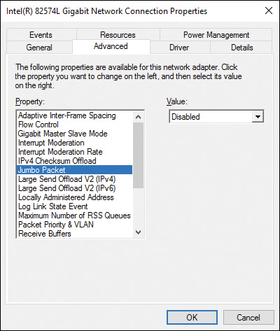
Figure 6-23 Advanced Tab of a Network Adapter Device with Several Configuration Options
The configuration settings available for the network adapter can vary widely. Wireless adapters will have different options than wired connections, and different devices from manufacturers expose different options through the driver interface. Typically you would not need to adjust any of these settings, but there are a few you should be aware of, and that may need to be changed for specific environments or application and network requirements.
Table 6-9 lists many of the more common options you may encounter and need to adjust.
Table 6-9 Important Network Adapter Advanced Properties
Property |
Adapter Type |
Description |
Preferred Band |
Wireless |
Some wireless networks can use 2.4 GHz or 5.2 GHz to communicate with the AP. You can adjust the preferred band to use. |
Wireless Mode |
Wireless |
Specify whether to use 802.11a, 802.11b, 802.11g, or some combination. |
802.11n Mode |
Wireless |
Specify whether to enable the ability to use 802.11n mode. |
Jumbo Packet/Jumbo Frames |
Wired |
For fast networks (gigabit or faster), enabling Jumbo Frames (also known as Jumbo Packet) can improve performance when all devices on a network path can transmit larger packets. |
Speed and Duplex |
Wired |
Typically the network adapter will negotiate with the switch to determine the speed and full- or half-duplex operation. If the autonegotiation is not working correctly, you can manually tell the adapter the speed and duplex mode to use. |
Transmit Buffers/Receive Buffers |
Wired |
These properties allow you to set the number of buffers used when moving data between memory and the network. Increasing the number of buffers consumes more system memory. |
Troubleshooting Network Issues
If there is an issue at the computer’s hardware layer, it can often be resolved by resetting the network adapter. You can perform this task from the device’s Properties dialog box. You can also do this from the Network and Sharing Center, by selecting the Change Adapter Settings link and right-clicking the connection, as shown in Figure 6-24. The adapter is reset by selecting Disable from the pop-up box, waiting for the adapter to shut down, and then selecting Enable from the right-click menu.
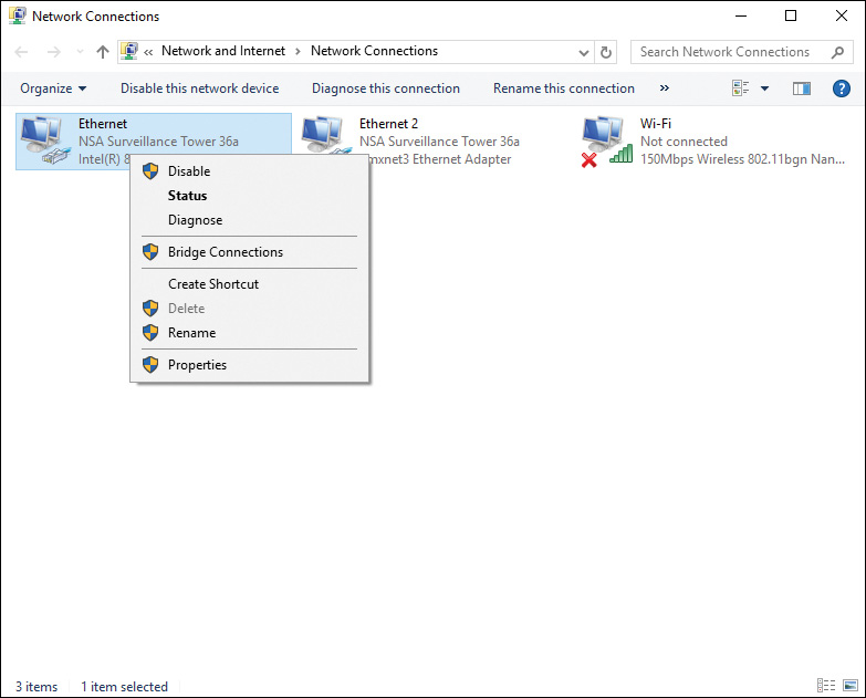
Figure 6-24 Enabling and Disabling a Network Adapter from the Network Connections Dialog Box
You can troubleshoot problems specific to the network adapter using the Windows 10 troubleshooting tool. To troubleshoot problems with the network adapter, follow these steps:
Step 1. Click Start, then scroll the program list that appears to select Windows System, and choose Control Panel.
Step 2. In the Search box, type troubleshooting, and then click the Troubleshooting link.
Step 3. From the Troubleshooting screen, click the Network and Internet link. This opens the dialog displayed in Figure 6-25.
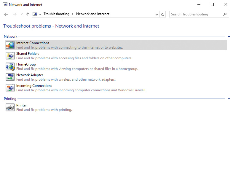
Figure 6-25 Network and Internet Troubleshooting Options
Step 4. Select the Network Adapter option to start the adapter troubleshooting wizard shown in Figure 6-26.
Figure 6-26 Network Adapter Troubleshooting Wizard
Step 5. To be most effective, the wizard can be run in Administrator mode. To do so, click the Advanced link, and then click Run as Administrator. Click the Next button to proceed.
Step 6. The wizard will run, starting diagnostics. If you have more than one network adapter, the wizard will then prompt you to select the adapter to troubleshoot, as shown in Figure 6-27. You can select a specific adapter or All Network Adapters. Click the Next button.

Figure 6-27 Selecting the Adapter to Use with the Network Adapter Troubleshooting Wizard
Step 7. The wizard diagnoses the adapter or adapters and attempts to fix any issues that are found.
When the wizard completes, it indicates whether any issues were found and whether the troubleshooter was able to fix them. You can click the View Detailed Information link to access a set of reports on the network adapter issues and the detection details. The report contains a lot of detailed information, and if the issue was not fixed, you can print the report for a hardware technician or vendor to help determine where the problem lies.
Exam Preparation Tasks
Review All the Key Topics
Review the most important topics in the chapter, noted with the Key Topics icon in the outer margin of the page. Table 6-10 lists a reference of these key topics and the page numbers on which each is found.
Table 6-10 Key Topics for Chapter 6
Key Topic Element |
Description |
Page Number |
IPv4 addressing components |
||
IPv4 address classes |
||
List |
IPv4 address bitwise calculations and masking |
|
Private IPv4 network addresses and ranges |
||
IPv6 address classes and subclasses |
||
List |
IPv4 to IPv6 intercommunication address types |
|
Step List |
Procedure to manually configure IPv4 addresses and DNS services |
|
Step List |
Procedure to manually configure IPv6 addresses and services |
|
Network and Sharing Center |
||
Step List |
Configuring a network adapter for IPv4 |
|
Step List |
Configuring a network adapter for IPv6 |
|
Using Set Up a Connection or Network Wizard to configure a network connection |
||
Advanced Sharing settings |
||
Step List |
Setting up Internet Connection Sharing (ICS) |
|
Characteristics of wireless networking protocols |
||
Step List |
Manually configuring a wireless network connection |
|
Setting up a manually configured wireless network connection |
||
Available wireless security types |
||
List |
How Windows determines which wireless network connection to prefer |
|
Using the netsh command to list network profiles |
||
Advanced tab of a network adapter and possible configuration options |
||
Important network adapter properties |
Complete the Tables and Lists from Memory
Print a copy of Appendix B, “Memory Tables” (found on the book website), or at least the section for this chapter, and complete the tables and lists from memory. Appendix C, “Memory Tables Answer Key,” also on the website, includes completed tables and lists to check your work.
Definitions of Key Terms
Define the following key terms from this chapter, and check your answers in the glossary.
802.11
AES
Address Resolution Protocol (ARP)
Anycast IPv6 address
Automatic Private IP Addressing (APIPA)
classless interdomain routing (CIDR)
default gateway
Domain Name System (DNS)
duplex
Dynamic Host Configuration Protocol (DHCP)
global unicast IPv6 address
host
Internet Connection Sharing
Internet Control Message Protocol (ICMP)
ipconfig
IP version 4 (IPv4)
IP version 6 (IPv6)
IP address
jumbo frames
link-local IPv6 address
Link-Local Multicast Name Resolution (LLMNR)
metered connection
multicast IPv6 address
Network Address Translation (NAT)
Network and Sharing Center
NIC
Service Set Identifier (SSID)
site-local IPv6 address
subnet mask
Teredo
WAP
WEP
WPA
wireless network profile
WLAN