
Introduction
In this chapter, an overview of bearingless drives and magnetic bearings is presented; the principle of radial force generation is discussed and a typical motor drive with magnetic bearings is introduced and compared with the bearingless drive. In addition, a definition of the bearingless motor is given and the related technologies and early developments are reviewed. Typical application structures, winding configurations, radial force and torque comparisons and applications are also included.
1.1 Magnetic bearing and motor drive
A new bearingless concept was introduced into ac drive technology in the late 1980s. Since then, the theory and background of the concept has been studied, with many test drives developed to gain experience of the operation and behaviour of a variety of bearingless ac drives.
Ac motor drive technology has been developed and applied in a wide range of applications since the 1970s because of their advantages over dc motor drives, such as high performance, compactness, lighter weight, use of low maintenance motors and lower motor cost. The increase in power and rotational speed of ac drives has widened the application area. One maintenance task that still remains with an ac drive is bearing lubrication and renewal. In some applications, bearing maintenance is still a significant problem. For example, the bearings can present a major problem in motor drive applications in outer space, and also in harsh environments with radiation and poisonous substances. In addition, lubrication oil cannot be used in high vacuum, ultra high and low temperature atmospheres and food and pharmacy processes. Hence motor drives with magnetic suspension can enlarge the possible application areas of motor drives.
Figure 1.1 shows the principles of rotor radial force generation in both the magnetic bearing and bearingless motors. A rotating shaft is surrounded by the stator core. The rotor and stator are magnetized with four poles in a north, south, north, south sequence. There are strong magnetic attractive forces under these magnetic poles between the rotor and the stator cores. For example, a magnetic force of 40 N is generated in 1 cm2 with an airgap flux density of 1 T. In Figure 1.1(a), these four magnetic poles have equal flux density and hence equal attractive force magnitudes. Thus, a vector sum of the four radial forces is zero. However, in Figure 1.1(b), one north pole is stronger than the other three poles so that the net attractive force is strong. Hence the unbalanced airgap flux density distribution results in radial magnetic force acting on the rotor. In this case, rotor radial force on the rotor is generated in the right-hand direction. In both radial magnetic bearing and bearingless motors, rotor radial force is generated by an unbalanced magnetic field; i.e., the rotor radial force is generated by the difference of radial forces between the magnetic poles. The attractive force is an inherently unstable force as it is stronger if the rotor moves in the force direction. The zero-radial-force point at the centre of the stator bore is an unstable point so that negative feedback is necessary.
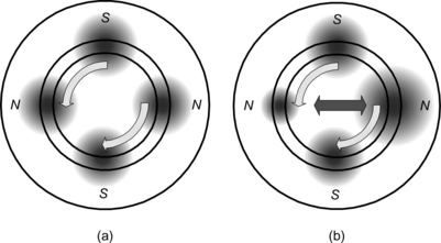
Figure 1.1 Radial force generation by unbalanced airgap flux density: (a) balanced airgap flux density; (b) unbalanced airgap flux density
In the Japanese Railways (JR) magnetically levitated train, the magnetic suspension force is generated by the interaction between the superconductor coil flux and an induced coil current. This means that a negative feedback controller is not required. In some flywheel applications, superconductor materials are used as magnetic bearings. These superconductor coils or materials provide stable magnetic suspension. However, the cost is quite high because a refrigerator and thermal insulation are required. These days, attractive magnetic force production requires simple, light-weight and cost-effective solutions for the magnetic suspension. Hence this book focuses on magnetic attractive forces.
Figure 1.2 shows the typical structure of a motor drive system equipped with magnetic bearings. The motor is located between the two radial magnetic bearings. Each radial magnetic bearing generates radial forces in two perpendicular radial axes. The radial forces are controlled by negative feedback control systems so that the radial shaft position is regulated to the centre of the stator bore. The left-hand magnetic bearing is regulated in two radial axis coordinates x1 and y1.
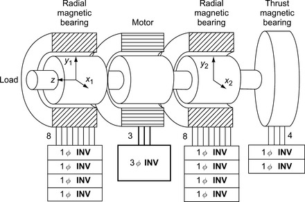
The right-hand radial magnetic bearing is regulated in radial axis coordinates x2 and y2. The thrust position on the z-axis, i.e., in the shaft direction, is regulated by axial forces generated by a thrust magnetic bearing. In total there are the five axes, x1, y1, x2, y2 and z, which are regulated by magnetic bearing systems.
Each radial magnetic bearing has four coils in a stator. Two coils are arranged on the x-axis and another two coils are on the y-axis. With a current in one coil, a magnetic attractive force is generated. A radial force in the x-axis direction is generated due to a difference in the magnetic attractive forces generated by the x-axis coils.
Coil currents in magnetic bearings are regulated by power-electronic circuits. In most cases, single-phase voltage-source inverters are utilized. A single-phase inverter can regulate one coil current so four single-phase inverters with eight output wires are necessary in a radial magnetic bearing.
In the thrust magnetic bearing, there are two coils so two single-phase inverters are connected to regulate the coil currents and generate radial force in axial direction.
The motor is responsible for generating torque around the shaft or z-axis. The rotational speed of the shaft is controlled by the motor torque and described by the torque equation of the system. A 3-phase inverter is connected to the motor terminals through three wires, with the motor windings connected in a wye or delta form (assuming 3-phase operation). The inverter supplies variable frequency and variable voltage based upon the shaft rotational speed and torque control requirements. The inverter frequency is proportional to the speed for most motors and the voltage/frequency ratio is usually almost constant up to the field weakening region.
1.2 Bearingless drives
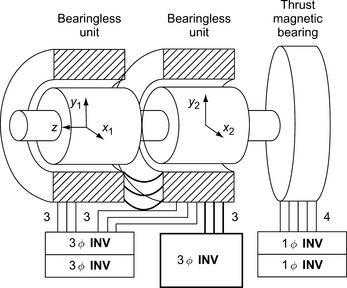
Figure 1.3 shows the structure of a bearingless drive. Two bearingless units are constructed on a single shaft. Each bearingless unit generates radial forces as well as rotational torque. The left-hand bearingless unit is responsible for x1 and y1 radial positioning while the right-hand unit is responsible for x2 and y2 positioning. The total drive torque is twice the rated torque of the bearingless unit because the units share the torque production. Each bearingless unit has three terminals for the suspension windings and another three terminals for the motor windings. The respective motor phase windings of each unit are connected in series as shown in Figure 1.3 so that a wye connection is formed with two series-connected phase windings in each phase leg. It is important that the series-connected phase windings and rotor are correctly aligned in both units so that if the motor current lies on the rotor q-axis in one unit then it also lies on the rotor q-axis of the other. A single 3-phase inverter is connected to the series-connected motor windings and supplies variable voltage and frequency for the motor drive. At the suspension winding terminals, two independent 3-phase inverters are connected to supply the required levitation currents in order to generate radial forces in four axes as dictated by negative feedback controllers and radial shaft position sensing.
One can see the following advantages of bearingless drives:
Compactness – The shaft length is short in a bearingless drive, resulting in high critical speeds and more stable operation.
Low cost – The number of wires is less in the bearingless drive. The number of inverters is also less. Low-cost standard 3-phase inverters are also employed.
High power – The bearingless drive can generate increased power if the shaft length is the same.
These advantages are realized as a result of the integration of a radial magnetic bearing and a motor.
1.3 Definition and related technologies
Table 1.1 gives two alternative definitions for the bearingless motor. The term “magnetically integrated” is very important. The drive shown in Figure 1.2 has an integrated magnetic bearing; however, it is only structurally integrated and not magnetically integrated. The drive in Figure 1.3 has magnetically integrated bearings.
Table 1.1
Definitions of a bearingless motor
1. A motor with a magnetically integrated bearing function.
2. A magnetic bearing with a magnetically integrated motor function.
Electrical engineers may feel familiar with the first definition because they may be familiar with motors. On the other hand mechanical engineers may feel familiar with the second definition. Therefore bearingless technology lies between electrical and mechanical engineering. It can also be noted that the bearingless generator can be defined. Most of the electrical motors can be used as generators.
Where does the term “bearingless” come from? Several researchers had used the term “bearingless” in their papers independently up to 1994. The origin of the word may be a simple modification of “brushless dc motors”. It is well known that “brushless dc motor” is used to describe an inverter-driven permanent magnet synchronous motor supplied with a quasi-square wave phase current (a sinusoidal phase current fed to the motor is a “brushless ac motor”). These have electrical characteristics similar to standard commutator-type dc motors, for example the rotational speed is proportional to the applied voltage. In commutator-type dc motors, the brushes are electro-mechanical contacts and can be a cause of troubles such as noise and sparking; they also have a limited lifetime and require maintenance. For dc motor users, the elimination of the brushes is very attractive. In a brushless dc motor the mechanical switching action of the commutator is replaced by electronic switching of the phase windings. Thus, inverter-driven synchronous motors are often called “brushless dc motors”.
These days, most of the maintenance requirement in an industrial drive is related to mechanical bearings. Lubrication oil should be replaced periodically. The bearings should also be replaced periodically, which requires the opening of the motor frame. If the shaft is suspended by a magnetic force, these maintenance tasks are not required. Hence going “bearingless” has many attractions for the motor user.
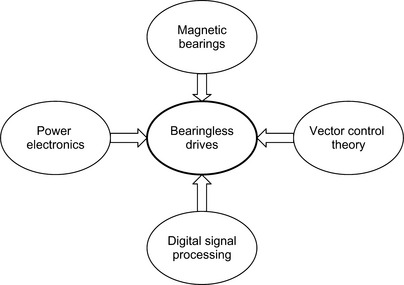
Figure 1.4 shows the related technologies of bearingless drives. The following significant developments have aided magnetic bearing technology:
1. Industrial experience and acceptance.
2. Radial positioning strategies such as inertial rotational centre alignment.
Power electronic technology has made a great contribution to the development of both magnetic bearing and bearingless motors. Instantaneous current control is possible with high switching-frequency IGBTs and MOSFETs. These power devices are now integrated into one power module. The power module includes six power devices forming a 3-phase inverter arrangement, as well as gate drive circuits and protection circuits, making the current regulation more reliable. Thanks to recent technological improvements, the cost of the current regulation system has decreased significantly and the cost of the power module has also decreased because mass-produced 3-phase voltage-source inverters are now widely used in industry and domestic appliances in such systems as variable-speed induction-motor and permanent magnet-motor drives. Most of the air-conditioners sold in Japan are driven by high-efficiency inverters. The benefits of low cost 3-phase inverters will further aid the development of the bearingless motor.
Digital signal processing has been improving over a period of time so the calculation speed has increased immensely while the cost has reduced. It should be noted that magnetic suspension requires relatively short sampling times compared with motor drives. This is because magnetic suspension is inherently unstable so that derivative or phase-lead controllers are necessary to realize stable magnetic suspension. In order to obtain phase margin at a crossover frequency, fast sampling is necessary. The requirement for the sampling frequency depends on mechanical inertia and stiffness design. Thanks to recent signal processing developments, such as digital signal processors and one-chip microprocessors, there is now enough calculation power to include fast calculation in a magnetic suspension system.
Bearingless motors often take advantage of the magnetic field set up by the motor winding currents. Therefore it is very important to have information about this revolving magnetic field. Controllers based on vector control theory provide instantaneous torque regulation as well as revolving magnetic field regulation. Hence the rotational position and amplitude of the magnetic field can be regulated. Based on the angular position and the amplitude of the motor magnetic field, radial forces are generated by generating additional magnetic fields using the suspension winding current. Therefore it can be said that bearingless technology stands on vector control theory. This leads to the fact that bearingless motors could not be realized before vector control theory (or, as it is sometimes called, field oriented control theory) was developed in the 1980s.
We can now see that bearingless motor technology was developed only after 1994 since it relies on four technologies that have only recently matured.
1.4 Early developments
Table 1.2 summarizes some notable developments of bearingless motors. In the middle of 1970s, a primitive electromagnet with stator windings having pole numbers of p and (p + 2) was proposed by Hermann [1–2]. This electromagnet was proposed as a motor which has a radial magnetic bearing function. Moreover, a split winding motor was proposed by Meinke [3]. However, development was limited since there was little knowledge of inverters, digital signal processors and field-oriented control theories at that time.
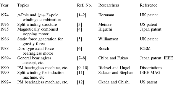
In 1985 a stepping motor, which was magnetically combined with a magnetic bearing, was proposed by Higuchi [4]. It included an inherently decoupled structure for torque and radial force, while taking an advantage of the motor exciting current.
In 1988, a stator winding structure with different pole combination was proposed for static force generation in order to support a rotor weight against gravity force [5]. In the same year, a disc type motor with axial force generation produced by adjusting the motor exciting current was proposed [6]. To the authors’ best knowledge, the word “bearingless” was used for the first time.
In 1989, the primary authors proposed a general concept for the bearingless motor [7]. Based on field-oriented theory, they concluded that most electrical machines can be used in a bearingless drive with additional suspension windings driven by a 3-phase inverter. The concept has been developed theoretically with strong support of Rahman [8]. Since then, the concept has been applied to synchronous reluctance, induction, permanent magnet and disc-type bearingless drives, as well as homopolar, hybrid and consequent-pole bearingless drives.
In 1990, Bichsel [9] finished his dissertation under supervision of Hugel of ETH, Zurich, Switzerland. They proposed a 6-pole permanent magnet rotor with 4-pole suspension windings as well as digital signal processor–controlled inverters. In the Zurich group, the continuous development in induction machine theory has led to the direct type of field-oriented control theory by Schoeb [10], Gempp and Redemann. Two-axis slice bearingless drives have also been developed by Barletta. The developments in ETH have been steadily spreading by co-operation with Amrhein and Silber.
It is also noted that radial force generation using split motor windings has been investigated by Salazar, Stephan and Watanabe [11].
The basic pole combination has been investigated by Okada and Ohishi [12] in Ibaraki University. Continuous developments for blood pump applications by Matsuda, Ueno and Masuzawa are also noted.
Since the middle of 1990s, development of the bearingless machine has been taking place in Switzerland, Austria, Germany, UK, France, Canada, USA, China, Korea and other places. Some authors refer to the bearingless motor in their own ways. Examples of alternative names are “bearing motor”, “bearing and drive”, “levitated motor”, “floating actuator”, “lateral force motor”, “combined motor-bearing”, “self bearing motor” and “integrated motor bearing”. These names provide an interesting selection of alternative names for the bearingless motor. However, most technical papers use “bearingless motor”. Hence it is recommended to use “bearingless motor” in technical writing for universal understanding.
1.5 Bearingless structures
In this section, several typical structures for the bearingless motor and generator are described. Two-axis active magnetic suspension, five-axis suspension and combinations of conventional magnetic bearings and mechanical bearings are included in the description.
Figure 1.5(a,b) shows two-axis active magnetic suspension. In Figure 1.5(a), a shaft is inserted into a rotor core. Two-axis magnetic suspension is realized by magnetic forces between the rotor and the stator. At the bottom of the shaft, a pivot bearing is located for axial and radial positioning of the shaft end. This structure is suitable for vertical shaft machines. On the other hand, in Figure 1.5(b), the shaft is removed. The two-axis active positioning provides passive magnetic suspension in tilting and axial motion. Hence there is a restriction in axial core length to realize passive suspension. However, with correct design, compact and low-cost bearingless drives of this form have been realized.

Figure 1.6(a–d) shows cross-sections of several arrangements for five-axis active suspension. Two bearingless units are required in order to generate radial forces in four axes. There is also a thrust magnetic bearing for active axial positioning on the fifth axis. In Figure 1.6(a), there are two rotors on the shaft acting in tandem. The rotor and the shaft are rotating inside two stator cores. A load machine such as a pump and compressor impeller can be attached to one end of the shaft. In Figure 1.6(b), the rotor is on the outside of the two stators. This structure is suitable for flywheel drives as well as digital video disk (DVD) and hard disk drives. The arrangement in Figure 1.6(c) is a modification of Figure 1.6(a). The shaft is hollow, allowing flow down the centre, and the thrust bearing is located between the bearingless units for full five-axis suspension. This structure is suitable for flow meters, canned pumps, spindles, etc. The hollow shaft can also be used for locating a wheel. In Figure 1.6(a–c), a thrust magnetic bearing is used. However, it is not necessary in some cases, where axial force is low or precise axial positioning is not required. In these cases, the axial positioning can be realized by passive positioning as shown in Figure 1.6(d), where the rotors in the bearingless units are naturally drawn to their axial centres by magnetic forces. Since the bearingless units generate considerable magnetic flux, the shaft experiences enough spring force under axial movement to keep the drive axially stable.
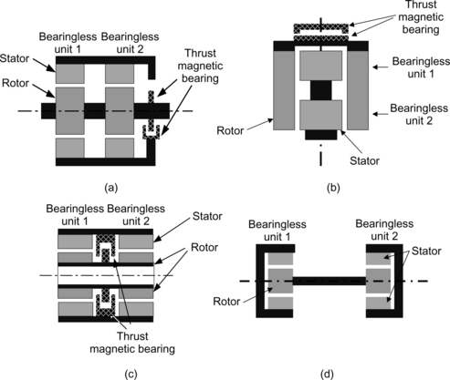
Figure 1.6 Five-axis active suspension variations: (a) inner rotor; (b) outer rotor; (c) hollow rotor; (d) load machine space on the shaft centre, 4-axis
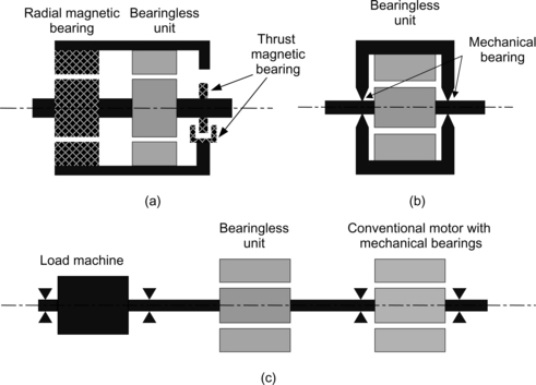
Figure 1.7(a–c) shows the cross-sections of different bearingless units when they are combined with conventional, mechanical or magnetic bearings. In Figure 1.7(a), the left-hand unit is a conventional radial magnetic bearing. Only the right-hand unit is a bearingless unit. This arrangement is suitable for a high radial force load connected to the left shaft end. In Figure 1.7(b), mechanical bearings are located at both ends of a bearingless unit. When the rotational speed is extremely high, the shaft has critical speeds caused by bending of the flexible shaft. At these speeds vibrations are produced. The bearingless unit can suppress these vibrations and support the shaft weight. In Figure 1.7(c), a load is driven by a conventional motor with a long shaft. The bearingless unit is located near the middle of the shaft in order to suppress shaft vibrations.
1.6 Comparisons
Table 1.3 compares several aspects of the different types of bearingless motor. The characteristics and performance criteria are divided into two parts, i.e., torque and force generation. Let us inspect the torque generation criteria. The motor efficiency is a ratio of shaft output and electrical input power. The efficiency is generally high in permanent magnet motors. They are also compact thanks to the recently developed rare-earth permanent magnets. Induction motors have a robust cylindrical rotor and smooth torque. Synchronous and switched reluctance motors have the advantage of low material costs so are suitable for mass production.
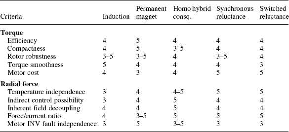
From the point of view of radial force generation, induction and permanent magnet motors are temperature dependent. In induction motors, the rotor resistance is a function of the rotor winding or cage temperature. The conductivity of the copper or aluminium can vary considerably over the operating temperature range of the machine, resulting in misalignment of the calculated field orientation in some cases. This misalignment of the field orientation sometimes results in shaft suspension problems. A similar problem may also occur in permanent magnet motors because the remanent magnetism (or strength) of permanent magnets decreases at high temperature. The variation is dependent on the magnet material. The discrepancy in magnet strength results in a field orientation calculation error. However, homopolar, switched reluctance and synchronous reluctance motors are robust in temperature variations since they do not have an electric circuit or magnets on the rotor.
When considering the possibility of indirect control, it should be remembered that the machine parameters depend on the level of magnetic saturation in synchronous and switched reluctance bearingless machines and, to a lesser extent, in interior and buried permanent magnet bearingless machines. As already mentioned, permanent magnet machine parameters also depend on temperature.
The decoupling of torque and radial force generation is excellent in homopolar, hybrid and consequent-pole bearingless motors. In these motors, the direction and amplitude of generated radial forces do not depend on torque generation (to any great extent). The radial force is mainly generated by an interaction of flux produced by suspension winding current and rotor magnets.
Suspension force produced by suspension current depends on the permeance of the paths that the generated flux follows. The relative permeability of permanent magnet is low. It is usually close to unity depending on the magnet’s material. Hence, permanent magnets can often be considered as airgap so that the magnets and airgap can be lumped together to give low permeance flux paths, producing high reluctance in the flux paths. This results in a low force/current ratio. This ratio is also low in squirrel-cage induction motors since the flux produced by the suspension winding current is damped by current in the rotor cage. This is because the suspension-current flux will induce electro motive forces (EMFs) into the cage, producing current and hence flux that will oppose the primary flux. This problem can be overcome by using pole-specific rotor bar connections in the rotor circuit. When using this sort of connection, most of the suspension winding current effectively generates suspension force so that the force/current ratio is as high as in reluctance motors. In synchronous and switched reluctance motors, the radial force/current ratio is high because of the high permeance of the levitation flux paths (in the aligned position in the case of a reluctance machine and on the d-axis in the case of a salient-pole synchronous machine). In addition, since the airgap between the rotor and stator is usually designed to be small in these types of motor, high permeance also exists for the main motor flux paths. In homopolar, hybrid and consequent-pole machines, the permeance of the flux paths can be designed to be high if the airgap length is as small as in reluctance machines, leading to a high force/current ratio.
It can be noted that the force/current ratio is easily improved with an increase in the number of series-connected conductors in the suspension windings. Therefore the force/current ratio is only meaningful if discussed under the condition of equal number of series turns.
The inverter fault tolerance is also an important aspect of bearingless motors. In some cases, motor current may be stopped because of a motor inverter fault. Even in this situation, magnetic suspension should continue in some applications to prevent further damage. In permanent magnet, hybrid and consequent-pole bearingless motors, magnetic suspension operates independently of the motor winding current by using the permanent magnet flux.
1.7 Winding structures
Table 1.4 summarizes various stator winding configurations. Conventional motors have 3-phase, 2-phase or single-phase windings. It is necessary to add 2- or 3-phase windings to generate radial force and various winding configurations have been proposed. The “4-pole and 2-pole winding” indicates a bearingless motor with a 4-pole motor winding set for torque generation as well as a 2-pole winding set for radial force generation. For example, 4-pole 3-phase windings and 2-pole 3-phase windings can be wound in a stator with a 4-pole permanent magnet rotor. This winding configuration applies in general to the theory of bearingless motors so it is applicable to various motor types such as induction and synchronous reluctance motors and permanent magnet motor types including surface-mounted, interior, inset and buried-spoke rotor configurations. The motor and the suspension windings are quite separate and the suspension winding operates using the differential principle.
Table 1.4
| Windings and operation | Winding combinations |
| Separated and differential | 4-Pole and 2-pole windings |
| Separated and differential | p-Pole and (p ± 2)-pole windings |
| Separated and differential | 2-Pole winding with homopolar rotor |
| Separated and differential | Short-pitch differential winding around stator poles |
| Separated and differential | Single-phase motor and 2-phase suspension winding |
| Motor common and current unbalance | Split motor windings |
The “4-pole and 2-pole winding” can also indicate a 2-pole motor winding and a 4-pole suspension winding, the functions of the winding sets are simply exchanged. A 2-pole revolving magnetic field is generated by the motor winding, so a 2-pole permanent magnet rotor is required. This winding strategy is well suited to magnetically cylindrical rotors, such as induction motors and surface-mounted permanent magnet motors. In salient-pole motors like synchronous reluctance or interior permanent magnet motors, the radial force is also a function of rotor angular position, so additional compensation is necessary. These winding structures are extensively described in this book.
The “2-pole winding with homopolar rotor” indicates a homopolar, a hybrid or, possibly but not necessarily, a consequent-pole bearingless machine. These machines have rotor poles excited in one direction only, i.e., the flux will cross the airgap once and return via another route. Thus, a 2-pole suspension winding Magneto Motive Force (MMF) is needed to generate an unbalanced magnetic field. Radial force is generated in the direction of the MMF. With the correct selection of the rotor magnetic pole number, a radial force is generated which is independent of the rotor angular position. The details are described in Chapter 14.
The “short-pitch differential winding” has short-pitch windings on each stator pole. This winding configuration is particular to switched reluctance motors although it is also used in compact permanent magnet motors with high statorslot fill and magnetic bearings. Differential windings can be wound over the motor windings so that the MMF can be made unsymmetrical in a controlled manner to produce an unbalanced flux distribution and hence generate a net radial magnetic force between the stator and rotor. As already mentioned, differential windings are applicable in permanent magnet motors; however, these windings are described in the chapter on switched reluctance type bearingless motors Chapter. Another way to generate radial force is to regulate the winding currents independently as illustrated in the split windings description in Chapter 16. Other winding structures are also described in Chapter 16.
1.8 Applications
There are several suitable applications of magnetically suspended motors and generators. Table 1.5 summarizes some applications. High-speed drives and generators require frequent bearing maintenance if mechanical bearings are fitted. However, magnetic suspension provides maintenance-free high-speed rotation. A flywheel drive and generator used in energy storage needs very low friction suspension. A satellite reaction wheel needs a rotating wheel for attitude regulation. In food and pharmacy processes, oil leaks caused by broken seals on mechanical bearings should be avoided. In harsh environments, such as in extremely low and high temperatures, as well as in vacuum, shaft suspension is always a problem. Pumps and blowers for poisonous, explosive and acidic gases and fluids also have problems with the mechanical seals although stainless steel cans with carbon bearings are usually employed. Magnetic suspension provides a long lifecycle and is maintenance-free.
Table 1.5
A swinging motor also has a problem with bearings. If the swinging motor operates 24 hours a day without a break, ball-bearing grease is dispersed, so the bearing lifetime is not guaranteed. Therefore magnetic suspension is an effective solution. More information on applications is given in the last chapter of this book.
References
[1] Hermann, P.K., “A Radial Active Magnetic Bearing”. London Patent No. 1 478 868, 1973. [20 November].
[2] Hermann, P.K., “A Radial Active Magnetic Bearing Having a Rotating Drive”. London Patent No. 1 500 809, 1974. [February 9].
[3] Meinke, P., Flachenecker, G., “Electromagnetic Drive Assembly for Rotary Bodies using a Magnetically Mounted Rotor”. United States Patent No. 3 988 658, 1974. [July 29].
[4] Higuchi, T., “Magnetically Floating Actuator Having Angular Positioning Function”. United States Patent No. 4 683 391, 1985. [March 12].
[5] Williamson, S. “Construction of Electrical Machine”. In: United States Patent No. 4 792 710. UK.; 1987. [February 20].
[6] Bosch, R., “Development of a Bearingless Electric Motor”. ICEM, 1988:373–375.
[7] Chiba, A., Fukao, T., “Electric Rotating Machinery with Radial Position Control Windings and its Rotor Radial Position Controller”. Japan Patent No. 2835522, 1989. [January].
[8] Chiba, A., Deido, T., Fukao, T., Rahman, M.A., “An Analysis of Bearingless AC Motors”. IEEE Transaction on Energy Conversion, Vol. 9, No. 1, 1994:61–68. [March].
[9] Bichsel, J., “Contributions on Bearingless Electric Motors”. ETH Thesis No. 9303, 1990.
[10] Schoeb, R., “Contributions on Bearingless Asynchronous Machines”. ETH Thesis No. 10417, 1993.
[11] Salazar, A.O., Dunford, W., Stephan, R., Watanabe, E., “A Magnetic Bearing System using Capacitive Sensors for Position Measurement”. IEEE Transanction on Magnetics, Vol. 26, No. 5, 1990:2541–2543. [September].
[12] Ohishi, T., “Magnetic Bearing Device with a Rotating Magnetic Field”. United States Patent No. 5 237 229, 1992. [April].