
Hardware
Domain Objectives
• 3.1 Explain basic cable types, features, and their purposes
• 3.2 Identify common connector types
• 3.3 Given a scenario, install RAM types
• 3.4 Given a scenario, select, install, and configure storage devices
• 3.5 Given a scenario, install and configure motherboards, CPUs, and add-on cards
• 3.6 Explain the purposes and uses of various peripheral types
• 3.7 Summarize power supply types and features
• 3.9 Given a scenario, install and configure common devices
• 3.10 Given a scenario, configure SOHO multifunction devices/printers and settings
• 3.11 Given a scenario, install and maintain various print technologies

Objective 3.1 Explain basic cable types, features, and their purposes
Objective 3.2 Identify common connector types
Although USB dominates external device connections, many other types of cables and connectors are used with laptops, desktops, and mobile devices, including network, video, and audio. In the following sections, you learn what they do and how to tell them apart from each other.

NOTE Because cables and connectors are closely related, we have combined the coverage of these two objectives.
Network Cables and Connectors
Network cables are used to connect computers and devices to wired networks ranging from LANs to the Internet. Network cables are available in three categories: twisted pair (Ethernet and phone), fiber, and coaxial (RG-59 and RG-6). Network cables use connectors ranging from RJ-45 and RJ-11 to BNC and various fiber types.
Let’s look at cables and connectors used for Ethernet first.
Ethernet
Ethernet cable is twisted-pair cable, which is comprised of eight tiny cables arranged in four wire pairs. Table 3.1/3.2-1 compares the characteristics of the major categories of Ethernet cable in use: Cat 5, Cat 5e, and Cat 6. These cables use RJ-45 connectors.
TABLE 3.1/3.2-1 Ethernet Cable Types Compared


EXAM TIP Although most Ethernet installations used twisted-pair cabling, Ethernet can also be carried over fiber optic cables and formerly used coaxial cable. In other words, an Ethernet network does not necessarily require Ethernet cable!
Most Ethernet cables are marked with the Cat number, as shown in Figure 3.1/3.2-1.

FIGURE 3.1/3.2-1 Cat 5e Ethernet cable
The maximum distance for a single Cat 5, 5e, or 6 cable run is 100 meters (about 328 feet). To go further, use repeaters.
Cross-Reference
RJ-45
Network interfaces come in several varieties. Most network interface cards (NICs) and motherboards have an 8-wire RJ-45 port (see Figure 3.1/3.2-2). RJ-45 connectors look like wide RJ-11 telephone connectors and plug into the female RJ-45 ports in the same manner that RJ-11 telephone cables plug into a modem.

FIGURE 3.1/3.2-2 An RJ-45 connecter and port
NOTE A network interface card (NIC) enables a computer to connect to a network. Techs call them NICs, even when the network adapter is built into a motherboard and thus is distinctly lacking in “card-ness.”
Unshielded Twisted Pair
Unshielded twisted pair (UTP) cabling consists of 22–26 AWG wire twisted into color-coded pairs. Each wire is insulated, and then the group is encased in a common jacket. The ANSI/TIA 568 standards specify several UTP categories that define maximum data transfer speeds (or bandwidth); these are printed on the cable. UTP is the predominate type of cable used in 10/100/1000Base T Ethernet installations.
Shielded Twisted Pair
The wire pairs in shielded twisted pair (STP) are wrapped in shielding to protect them from electromagnetic interference (EMI). STP is rare because few cables run in EMI-heavy settings such as a shop floor crowded with electric motors.
Plenum
Each horizontal cabling run is usually Cat 5e or better UTP. Most of the cabling runs in the plenum space, the space above the ceiling, under the floors, or in the walls.
This has two implications:
• If the PVC (polyvinyl chloride) protective jacket on standard network cables burns, it produces dangerous fumes that can spread quickly via the plenum space. Instead, we must use more expensive plenum-grade cable with a fire-retardant jacket.
• The protection afforded by the plenum space means we can use faster solid-core UTP cable with a single fragile solid wire, instead of slower, damage-resistant stranded-core UTP with a bundle of tiny wire strands that don’t conduct as well.
568A/B
If you wire your own connectors, you can technically order the wires however you like if you use the same pairings on each end, but you should pick either the ANSI/TIA 568A (T568A) or the ANSI/TIA 568B (T568B) standard—and save yourself time later by keeping good records. The pins in UTP are numbered (as shown in Figure 3.1/3.2-3), but each matching wire just has a standardized color, as detailed in Table 3.1/3.2-2.
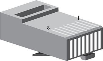
FIGURE 3.1/3.2-3 RJ-45 pin numbers
TABLE 3.2-2 UTP Cabling Color Chart

RJ-11
Dial-up and DSL modem ports look identical to traditional wired telephone jacks and use two-wire RJ-11 telephone cables and connectors (see Figure 3.1/3.2-4). The locking clips on the male RJ-11 connectors secure the cable into the port. Most modems also have an output port for a telephone.

FIGURE 3.1/3.2-4 RJ-11 connectors on a modem
Fiber
Fiber optic cable uses light to transmit Ethernet network frames, which makes it immune to electrical problems such as lightning, short circuits, and static. Fiber optic signals also travel 2000 meters (2 km) or more. Most fiber Ethernet networks use 62.5/125 multimode fiber optic cable. Fiber optics are half-duplex; data flows only one way, so fiber connections require two cables.
The most common fiber connectors are ST, SC, and LC (see Figure 3.1/3.2-5). Other fiber connectors that you might see are FDDI, MT-RJ, and FC.
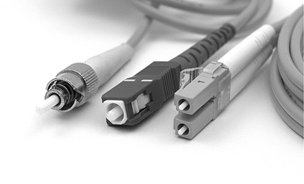
FIGURE 3.1/3.2-5 ST (left), SC (center), and LC (right) fiber connectors
EXAM TIP It’s not important to memorize the different types of fiber optic connectors.
If you want to use fiber optic cabling, you need a fiber optic switch and fiber optic network cards. Regardless of fiber’s impressive theoretical speed and range, real-world fiber networks are limited to the speed and distance specified by their respective Ethernet standard. The record single-mode transmission way back in 2011 was 100 terabits per second over 100 miles, but you won’t find Ethernet standards anywhere near that (yet). Multimode networks run from 10 to 10,000 Mbps up to ~600 meters.
NOTE Fiber networks use laser or LED light sources. In single mode, lasers pulse single bursts over long distances at incredible speeds. Multimode fiber carries multiple simultaneous LED signals using different reflection angles within the core of the cable. These reflection angles disperse over long distances, limiting multimode to relatively short distances.
Coaxial
Coax consists of a core cable, surrounded by insulation, covered with a shield of braided cable (see Figure 3.1/3.2-6) to eliminate interference, and wrapped with a protective cover. Early versions of Ethernet ran on coaxial cable instead of UTP, and coax lives on for cable modems and satellite connections.

FIGURE 3.1/3.2-6 Typical coax
There are hundreds of RG ratings for coax, but you just need to know RG-59 and RG-6 for the CompTIA A+ 220-1001 exam; the RG rating is marked on the cable. Both have a 75-ohm impedance and are used in cable television, but RG-59 is thinner and can’t carry data as far as RG-6, which is the standard for HD video. Coax generally tops out around 100 Mbps. Recommended maximum length without using amplifiers is about 400 meters.
EXAM TIP Be sure you are familiar with the various network cable types. As CompTIA specifically lists under objective 3.1 for network cables, know their speed and transmission limitations.
BNC
Very old NICs might have a bayonet-style coax connector called a BNC connector (see Figure 3.1/3.2-7), used for 10Base2 or Thinnet (10 Mbps) Ethernet networking. You won’t see these connectors on working systems, but you might on the exam! Maximum segment length is 185 meters (about 606 feet).

FIGURE 3.1/3.2-7 BNC connector and terminator used on 10Base2 network cards
Video Cables and Connectors
Video cables connect displays, monitors, HDTVs, and projectors to your computer’s video card or onboard video port. Table 3.1/3.2-3 provides an overview of these cables and connector types.
TABLE 3.1/3.2-3 Video Cables
Figure 3.1/3.2-8 illustrates some of these video cables and Figure 3.1/3.2-9 illustrates most of these video ports.

FIGURE 3.1/3.2-8 Typical HDMI, Mini-HDMI, DP, and mDP cables/connectors (left to right)
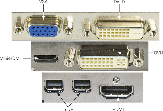
FIGURE 3.1/3.2-9 Typical video ports
Multipurpose Cables
Modern computers use one or more multifunction ports to connect a host of useful peripherals. All newer machines have universal serial bus (USB) ports, and some have additional ports such as Thunderbolt. Mobile devices have USB or Lightning ports.
Lightning
With the iPhone 5, Apple replaced its older 30-pin connector with its proprietary 8-pin Lightning connector (see Figure 3.1/3.2-10), which can be inserted in both up and down orientations—it’s not “keyed” to a single orientation. Licensed Lightning connectors have a small verification chip, and knock-off cables without it typically won’t work or will have only limited use.
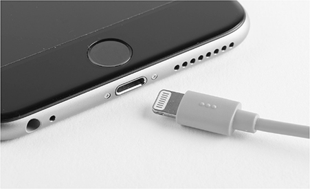
FIGURE 3.1/3.2-10 Lightning connector
EXAM TIP The Apple Lightning standard is the poster child for proprietary vendor-specific ports and connectors. Only iOS devices use Lightning for communication and power. Android and Windows mobile devices typically use industry-standard, vendor-neutral ports and connectors.
Thunderbolt
Intel and Apple developed the Thunderbolt interface as a high-speed alternative to existing technologies such as USB and FireWire to connect peripherals via PCIe and DisplayPort simultaneously, combining their capacity. Consult Table 3.1/3.2-4 for the basics on each version of the Thunderbolt standard.
TABLE 3.1/3.2-4 Thunderbolt Standards

Thunderbolt can use copper or fiber cabling, though the fiber optic cables are still pretty rare. The copper cables can run up to 3 meters (whether a single cable, or chained). Optical runs can extend much farther—up to 60 meters—but optical cables of that length are several hundred dollars, and you’ll need another way to power the device.
The only way to tell the difference between a standard DisplayPort and a Thunderbolt 1 or 2 port (see Figure 3.1/3.2-11) is that the latter has a little lightning bolt symbol next to it—and you’ll need the same trick to tell a Thunderbolt 3 port apart from a regular USB Type-C port.
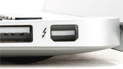
FIGURE 3.1/3.2-11 Thunderbolt 2 port
USB
USB (universal serial bus) is a large family of hot-swappable connectors that, as the name implies, can be used to interface almost anything to a PC or mobile device. USB works with IT essentials such as keyboards, mice, joysticks, microphones, scanners, printers, modems, tablets, and digital cameras as well as eccentric office gadgets such as lap warmers, cup heaters, personal fans, and many more.
The core of USB is the USB host controller, an integrated circuit normally built into the chipset. It acts as the interface between the system and every USB device that connects to it. The USB root hub is the part of the host controller that makes the physical connection to the USB ports. A USB host controller is the boss (the master) of any device (the slave) that plugs into that host controller. The host controller performs two tasks: sending commands and providing power to connected USB devices. The host controller is upstream, controlling devices connected downstream to it. The host controller is shared by every device plugged into it, so speed and power are reduced with each new device.
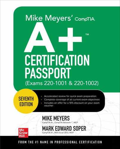
You can add extra USB ports to a system using either a USB expansion card or a USB hub (see Figure 3.1/3.2-12). USB hubs come in powered and bus-powered varieties. Powered USB devices have their own power plug, whereas bus-powered USB devices do not and instead draw their power from the USB bus. Too many bus-powered devices on a bus-powered hub can cause problems, so it’s best to use powered hubs in such situations.

FIGURE 3.1/3.2-12 Typical USB hub

ADDITIONAL RESOURCES For more information about USB, visit www.usb.org.
USB devices are hot-swappable, which means that you can connect or disconnect them at any time without powering down your computer. USB technology lets you use hubs to connect up to 127 devices to a single host controller on your computer.
EXAM TIP For the CompTIA A+ 220-1001 exam, you need to know that you can connect 127 devices to a single USB port. But for real-life, on-the-job situations, it’s a bad idea to hit this maximum. Some applications reserve bandwidth, and you could wind up with quite a mess. Too much of a good thing isn’t good!
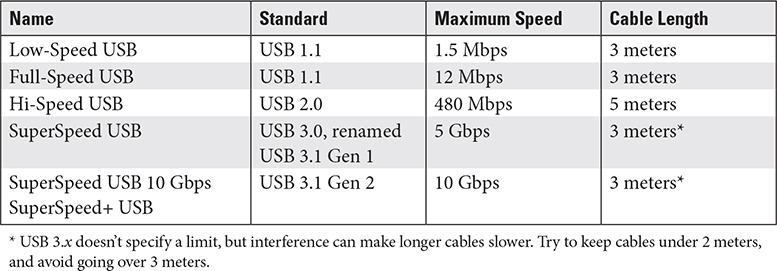
There have been several generations of USB standard, along with a number of connector types; let’s start with the standards. Table 3.1/3.2-5 provides a quick reference to help you sort them out.
TABLE 3.1/3.2-5 USB Standards
USB offers many connector types that are interchangeable among the many versions, for the most part. Whether a PC has a USB 1.1 or USB 2.0 port, for example, you can plug a Type-A connector into it. (Type-A is the ubiquitous rectangular connector type that’s been around for two decades and is notorious for plugging into the port in whichever orientation is the reverse of your first attempt.) USB 3.x uses separate and clearly marked ports and connectors. The USB 3.0 standard suggests that the ports should be colored blue to differentiate them from earlier versions, although this is not universally followed. The latter ports are usually black. You can still plug older USB devices into a USB 3.0 port, but they will run at the slower speeds. You can also plug USB 3.0 devices into an older USB port, but they will also run at the slower speeds.
Table 3.1/3.2-6 lists the common USB connectors and their purposes. Note that “keyed” means the plug fits into the socket in only one direction.
TABLE 3.1/3.2-6 USB Connection Types

Figures 3.1/3.2-13 and 3.1/3.2-14 illustrate connector types discussed in Table 3.1/3.2-6.
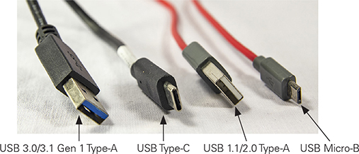
FIGURE 3.1/3.2-13 USB Type-A, Type-C, and Micro-B cables

FIGURE 3.1/3.2-14 USB 2.0 and USB 3.0 Type-B and Micro-B cables
EXAM TIP CompTIA uses the term USB-C for what others call USB Type-C. CompTIA also uses the term Micro-USB for USB Micro-B and Mini-USB for USB Mini-B. You might see either form on the exam.
The USB Type-C connector is now being used on the latest Android smartphones and tablets, on Apple’s latest iPad tablets, as well as on many desktop and laptop computers. Like the Lightning connector, the USB Type-C connector is not keyed, making it easier to buy interoperable cables. USB-C is a form factor, not a specification. USB-C ports might run at USB 3.1 Gen 2, USB 3.1 Gen 1, or USB 2.0 speeds; check the device’s specifications to find out.
EXAM TIP You will likely see micro- and mini-USB, USB Type-C, and Lightning mobile device connection types on the exam. Know their characteristics and differences.
Serial (RS-232) Cable
Most peripherals connect via some type of USB port, but a few desktop systems still include support for specialized peripheral cables, such as the serial (RS-232) cable.
The RS-232 cable is a programmable interface that supported many types of slow-speed peripherals, including dial-up modems, early mice, and early printers. RS-232 ports use a 9-pin DB-9 connector and use software configuration to set up the port to communicate with the devices attached to the other end of the cable. USB ports can be used to connect to serial devices through a USB-RS-232 adapter. Figure 3.1/3.2-15 illustrates an RS-232 port and an RS-232 modem cable connector.

FIGURE 3.1/3.2-15 RS-232 port and cable connector
Hard Drive Cables
CompTIA A+ 220-1001 exam objective 3.1 refers to “hard drive cables,” but it’s important for you to realize that these cable types are also used by other types of mass storage devices, such as SSDs, optical drives, and tape drives. Different types of cables are used by different types of hard drive and mass storage devices.
SATA and eSATA
Advanced Technology Attachment (ATA) drives have been around for over three decades, though serial ATA (SATA) is the one used for current hard drives and optical drives. SATA creates a point-to-point connection (see Figure 3.1/3.2-16) between a SATA device, such as a hard drive or optical drive, and the SATA controller.
A SATA device’s stream of data traverses a thin 7-wire cable that can reach up to a meter; speeds depend on which version of the SATA standard is in use. The versions—1.0 (1.5 Gbps), 2.0 (3 Gbps), and 3.0 (6 Gbps)—have a maximum throughput of 150 MBps, 300 MBps, and 600 MBps, respectively.
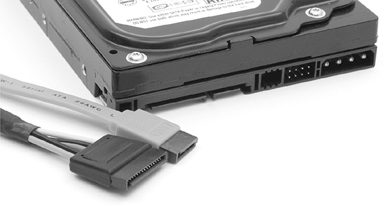
FIGURE 3.1/3.2-16 SATA power (wide) and data (narrow) cables and drive connectors
External SATA (eSATA) extends the SATA bus to external devices at the same speed as the internal SATA bus. The connector (see Figure 3.1/3.2-17) is similar to internal SATA but is keyed differently; it supports cables up to 2 meters outside the case and is hot-swappable.

FIGURE 3.1/3.2-17 eSATA connectors (in center of photo)
EXAM TIP If you encounter the term hot-swappable on the exam, keep in mind that a hot-swappable drive will be recognized even if it is connected, swapped, or replaced while the system is running.
IDE
Integrated Drive Electronics (IDE) is the name used on the CompTIA A+ exam for what is also known as ATA or Parallel ATA (PATA) drives. These drives use a 40-wire flat ribbon cable to connect one or two drives to a host adapter built into a motherboard or an add-on card. IDE interfaces are found on legacy systems, although a few more-recent computers that use SATA for hard drives also use IDE for optical drives. Figure 3.1/3.2-18 shows an 80-wire IDE cable and an older, slower 40-wire IDE cable.

FIGURE 3.1/3.2-18 80-wire (left) and 40-wire (right) IDE cables
EXAM TIP Although CompTIA uses the term IDE on the exam, the interface is more often referred to as PATA or ATA/IDE by the industry. They’re the same thing, so be prepared!
SCSI
Small Computer System Interface (SCSI) refers to a large family of internal and external drive and device connectors. Internal SCSI devices such as tape drives and hard drives are used only by servers, and connect via 50-wire or 68-wire flat cables that resemble wider versions of IDE cables. External SCSI devices use bulky round cables ranging from 25 pins to 68 pins. Each SCSI device is assigned an ID number, enabling multiple devices to be connected to a single host adapter using daisy-chaining. Unless you work with servers, it’s unlikely you will encounter a SCSI host adapter or device in the field.
NOTE SCSI has largely been replaced by Serial Attached SCSI (SAS) for servers and storage arrays. SAS-3, the latest version, runs at up to 12 Gbps. SAS interfaces also support SATA drives. There are over a dozen SAS connector types, some of which resemble bulked-up SATA interfaces.
Molex
Internal hard drives also need power. For IDE (ATA, PATA) drives, the 4-pin Molex power connector is the standard choice. Molex can also be adapted to provide power for other types of devices and is often used for case fans.
The smaller Berg (aka mini) power connector is used primarily by floppy drives. Figure 3.1/3.2-19 compares Molex and Berg power connectors.

FIGURE 3.1/3.2-19 Molex and Berg power connectors
Adapters
Adapters and converters enable you to connect devices in interesting ways. You can use a cable with DVI on one end and HDMI on the other end, for example, to plug into a DVI port on the video card and the HDMI socket on the monitor. These devices fall into two broad categories based on the problems they solve: connecting one type of video cable or port to another, and connecting almost anything to USB.
DVI to HDMI, DVI to VGA
Adapters and converters for video take two primary forms: relatively small devices that fit at one end of a cable, converting it to the desired interface, and cables with built-in converters that have different connectors on each end. The former are more flexible, but the latter are easier to use. Figure 3.1/3.2-20 illustrates a DVI-to-HDMI cable, and Figure 3.1/3.2-21 illustrates a DVI-to-VGA adapter.

FIGURE 3.1/3.2-20 DVI-to-HDMI cable
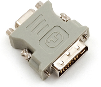
FIGURE 3.1/3.2-21 DVI-to-VGA adapter enables a DVI-I port to work with VGA displays.
USB to Ethernet
There are many USB adapters for different types of devices, but the most common one is the USB to Ethernet (RJ-45) adapter, as it enables computers without Ethernet ports to connect to a twisted-pair Ethernet network (see Figure 3.1/3.2-22).

FIGURE 3.1/3.2-22 USB to Ethernet adapter enables a USB port to connect to an Ethernet network.
NOTE Other USB adapters you might encounter include PS/2 to USB, USB A to USB B, USB to Bluetooth, USB to Optical Drive, and USB to Wi-Fi.
REVIEW
Objective 3.1: Explain basic cable types, features, and their purposes
Objective 3.2: Identify common connector types
• The most common type of network cable is Ethernet, commonly available in Cat 5, 5e, and 6 speed grades.
• Ethernet uses the RJ-45 connector.
• Plenum-grade cables are designed for use in plenum (air spaces) and are fire-resistant.
• UTP cables are used in the vast majority of 10/100/1000BaseT networks.
• STP cables are shielded for use in areas of EMI and typically are used only in such environments.
• The 568A and 568B cable standards for connecting the RJ-45 connector to UTP cable differ in their use of white/green, green, orange, and white/orange wires.
• An RJ-11 connector resembles an RJ-45 connector but is smaller and is used for telephone-based Internet service (dial-up or DSL).
• Coaxial cable is used for cable TV and Internet. RG-6 is the most common type, but RG-59 may be found in older installations.
• A coaxial cable that uses BNC, such as 10Base2 Ethernet, has a T-shaped BNC connector that cables are attached to; if the connector is at the end of the cable run, a terminator is used in place of one of the cables.
• Fiber optic cabling can be used for Ethernet network, and common connectors include ST, SC, and LC.
• VGA carries analog signals.
• DVI-I carries digital and analog signals and can be adapted to VGA.
• DVI-D carries digital signals only.
• HDMI carries HD video and audio signals. Mini-HMDI is a reduced-size version of HDMI.
• DisplayPort also carries HD video and audio signals. Mini DisplayPort is a reduced-size version of DisplayPort.
• Lighting is used for data transfer and charging by recent iOS devices.
• Thunderbolt is a very high-bandwidth video and storage standard that uses Mini DisplayPort or USB-C depending upon version.
• USB is available in speeds from 12 Mbps (USB 1.1) up to 10 Gbps (USB 3.1 Gen 2).
• USB Type-A ports connect to computers or hubs.
• USB Type-A, Mini-B, and Micro-B ports connect to devices.
• USB On the Go is used by many Android tablets and smartphones.
• USB-C is the first unkeyed USB form factor and works for both computers and devices.
• RS-232 serial ports for older types of slow-speed peripherals use a 9-pin DB-9 connector.
• SATA is used for mechanical and SSD hard drives, optical drives, and tape drives (on servers).
• IDE was also called PATA and was formerly used for mechanical hard drives and optical drives.
• SCSI is a large family of daisy-chained storage and scanning peripherals that are found in servers, but not PCs. The latest version of SCSI is called Serial Attached SCSI or SAS.
• Adapters such as DVI-to-HDMI, USB-to-Ethernet, and DVI-to-VGA enable DVI and USB ports to handle other types of devices.
• eSATA enables the high-speed SATA bus to be used by external drives; it has been largely replaced by USB 3.0 and USB 3.1.
• Molex provides power for IDE drives and internal fans and can be adapted to provide power for SATA and floppy drives.
3.1/3.2 QUESTIONS
1. Company A wants to eliminate separate speakers on desktops and use speakers built into monitors. Which of the following video card standards should be specified?
A. DVI-I
B. DVI-D
C. VGA
D. HDMI
2. Company B is planning to upgrade its Fast Ethernet network to Gigabit Ethernet. In checking existing cables, the network techs have discovered that some areas were wired with Cat 5, some with Cat 5e, and some with Cat 6. Which of the following should they do as part of the upgrade process?
A. Replace all cables with Cat 6
B. Keep the same cables
C. Replace Cat 5 with Cat 5e or Cat 6
D. Replace all cables with Cat 5e
3. Company C has purchased some new computers that have USB 3.0 ports as well as a USB-C port. It wants to use the USB-C port for very fast external SSD drives. What needs to be determined first?
A. Are USB-C SSD drives available?
B. How fast is the USB-C port?
C. Can the USB-C port work with other form factors?
D. Is USB-C always running at 10 Gbps?
4. Company D wants to run coaxial cable in its offices for use with HDTV. Which of the following cable types should the company specify?
A. RG-6
B. STP Cat 5e
C. STP Cat 6
D. RG-59
5. Company E wants to purchase SuperSpeed USB drives and card readers. However, all its techs can find are devices labeled with a USB version number. Which of the following USB versions does the company need?
A. USB 3.1 Gen 2
B. USB 3.0
C. USB 1.1
D. USB 2.0
3.1/3.2 ANSWERS
1. D HDMI carries HD audio and HD video signals.
2. C Cat 5e and Cat 6 both support Gigabit Ethernet, so either could be used as a replacement for Cat 5.
3. B USB-C can support USB 2.0, USB 3.0/USB 3.1 Gen 1, or USB 3.1 Gen 2 speeds. Check the system documentation.
4. A RG-6 is the standard for HD video.
5. B USB 3.0 is the version number for SuperSpeed USB. It is also known as USB 3.1 Gen 1.
Objective 3.3 Given a scenario, install RAM types
Computer users are curious people, and before long one of them is going to ask you, the learned tech, “Where are programs stored as they run?” Without hesitation, you might answer, “In system RAM, of course!”
Many computer users falsely believe that programs run directly off of the hard drive. This is rarely the case, because even the fastest hard drive can’t keep up with the slowest CPU. Instead, programs must be copied to a super-fast medium that can supply the CPU with the data it needs to run an application at a speed it can use: this is the function of RAM. Launching an application loads the necessary files from the hard drive into RAM, where the CPU can access the data to run the program.
NOTE Technically, you can use a hard drive or flash drive as virtual memory to expand available RAM, but these devices are not nearly as fast as RAM, and it isn’t quite the same as running a program from where it is stored on a hard drive.
RAM was once a precious commodity, and even a small upgrade cost hundreds of dollars. These days, it’s not very expensive to add more RAM, and it is often the best upgrade for a sluggish system. This doesn’t mean that you can just grab any type of RAM; you’ve got to match the motherboard with the right type of RAM, running at the right speed. Manufacturers have produced RAM in many physical form factors (sometimes called packages) and technologies over the years. This section looks at the types of RAM covered in objective 3.3 of the CompTIA A+ 220-1001 exam.
Desktop RAM
Desktop computers use a type of RAM known as dual inline memory modules (DIMMs). The latest systems use DDR4 DIMMS, but you also need to know about DDR2 and DDR3 DIMMs for the 220-1001 exam.
DDR2
DDR2 DIMMs have a flat connector along the bottom with 240 pins. The previous memory type, DDR, also has a flat connector with 240 pins. To distinguish DDR2 from DDR, note that DDR2 modules have their alignment notch located slightly to the left from where it is found on DDR modules (see Figure 3.3-1).
The big speed increase from DDR2 compared to regular DDR comes by clock-doubling the input/output circuits on the chips (instead of speeding up the memory itself) and adding special 4-bit buffers (sort of like a cache). Table 3.3-1 shows common DDR2 speeds.
TABLE 3.3-1 DDR2 Speeds

NOTE The PC2-#### that often follows the name of a DDR2 stick—such as DDR2-400 (PC2-3200)—refers to the data throughput possible with that particular stick. A DDR2-400 stick, therefore, has a bandwidth of 3.2 GB per second (GBps). PC3 refers to DDR3, and PC4 refers to DDR4.
Typical sizes of DDR2 DIMM sticks range from 512 MB up to 4 GB.
DDR3
DDR3 boasts higher speeds, more efficient architecture, and around 30 percent lower power consumption than DDR2. Desktop DDR3 uses a 240-pin DIMM (slotted differently than 240-pin DDR2 or DDR); the sticks are not interchangeable (refer to Figure 3.3-1).
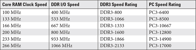
DDR3 doubles the size of the prefetch buffers from 4 bits to 8 bits, giving its bandwidth a huge boost when reading contiguous data. Table 3.3-2 lists common DDR3 speeds. Many DDR3 systems support dual- and triple-channel memory configurations.
TABLE 3.3-2 DDR3 Speeds
Typical sizes of DDR3 DIMM sticks range from 1 GB up to 8 GB.
DDR4
Compared to DDR3, DDR4 offers higher speeds, more efficient architecture, and around 20 percent lower power consumption. Desktop DDR4 uses a 288-pin DIMM that has a slight curve on both ends of its motherboard connector (refer to Figure 3.3-1).

FIGURE 3.3-1 DDR, DDR2, DDR3, and DDR4 DIMMs compared
Table 3.3-3 lists common DDR4 speeds.
Typical sizes of DDR4 DIMM sticks range from 4 GB up to 64 GB.
EXAM TIP You should be familiar with the various RAM speeds for DDR2, DDR3, and DDR4.
ADDITIONAL RESOURCES To familiarize yourself with the many RAM standards and specifications for both desktops and laptops, visit www.crucial.com. Pay special attention to descriptions such as module size, package, and features. Be sure to check out Crucial’s memory compatibility tools while you’re there.
TABLE 3.3-3 DDR4 Speeds

Handling and Installing DIMM Sticks
Proper RAM handling and installation procedures prevent damage to your system. This section reviews the proper way to handle desktop RAM and how to install it.
RAM is extremely sensitive to ESD, so take precautions while transporting, handling, and installing it. Always store RAM in anti-static bags or sleeves when it’s not installed on a computer, and keep it labeled with the type, size, and speed so that you can identify it later. Wear an anti-static wrist strap and ground yourself before working with RAM. Don’t take a RAM stick out of its bag before you actually need to install it. Handle RAM by the edges, and avoid touching the contacts or circuits.
To install DIMM modules, first power down the computer and unplug it from the AC outlet. DIMM sticks fit into their sockets vertically. You’ll note on the motherboard that the guide notches on the sockets match up to the notches on the RAM (refer back to Figure 3.3-1) to prevent you from inserting it the wrong way. Make sure that the RAM retention clips at either end of the socket are pushed completely outward.
Hold the RAM stick by the edges, position it above the RAM socket, and press it straight down into the slot with gentle pressure (see Figure 3.3-2). When the RAM is fully inserted, the retention clips will rotate into the retention notches on each end of the stick. Snap the clips firmly into place, and you’re done.

FIGURE 3.3-2 Properly seating a DIMM module
Barring ESD, not a lot can go wrong. The main thing to look for is improper seating. If the retention clip doesn’t engage fully, your RAM stick isn’t inserted completely. Note that DDR2/DDR3 sockets typically use a retention clip on both ends, while DDR4 sockets use a retention clip on one end and a fixed guide rail on the other end. Double-check the positioning, and insert the RAM again. If it doesn’t go in easily, it’s not in the right position.
To remove a DIMM, push the retention clip(s) on the socket outward. These clips act as levers to eject the stick partially so that you can then pull it all the way out.
Laptop RAM
Laptops use DDR2, DDR3, and DDR4 RAM, just as desktops do, but laptop RAM is packaged in a smaller form factor known as small-outline DIMM, or SO-DIMM (sometimes spelled without the hyphen, SODIMM, as in the exam objectives). Thus, DIMMs and SO-DIMMs are not interchangeable with each other (see Figure 3.3-3). Note that some all-in-one and small form factor desktop computers also use SO-DIMMs.

FIGURE 3.3-3 SO-DIMM module (top) and DIMM module (DDR3) compared
The performance characteristics of SO-DIMM modules using a given memory technology are similar to those of DIMM modules using the same technology; thus the information in Tables 3.3-1, 3.3-2, and 3.3-3 apply to both DIMM and SO-DIMM modules. Figure 3.3-4 shows the position of the alignment notch in the DDR2, DDR3, and DDR4 SO-DIMMs.

FIGURE 3.3-4 DDR2, DDR3, and DDR4 SO-DIMMs compared
• DDR2 SO-DIMM DDR2 SO-DIMM is packaged in a 200-pin module, such as the one shown in Figure 3.3-4.
• DDR3 SO-DIMM DDR3 SO-DIMM is packaged in a 204-pin module, such as the one shown in Figure 3.3-4. Note that some DDR3 SO-DIMMs use low-voltage DDR3 memory. These modules are called DDR3L SO-DIMM. Check the specifications for a specific device to determine if it uses standard-voltage (DDR3) or low-voltage (DDR3L) memory.
• DDR4 SO-DIMM DDR4 SO-DIMM is packaged in a 260-pin module, such as the one shown in Figure 3.3-4. A DDR4 SO-DIMM module is slightly wider than previous SO-DIMM types.
EXAM TIP Memorize the DIMM and SO-DIMM form factors—and the associated memory technologies—for the CompTIA A+ 220-1001 exam. Be prepared for questions that require you to know the number of pins to differentiate between DIMM and SO-DIMM modules.
Handling and Installing SO-DIMM Sticks
Just like with a desktop, protect yourself and the portable by removing all power and protect the SO-DIMM modules by using proper ESD avoidance techniques. With portables, removing power includes disconnecting removable batteries. If it has built-in batteries, consult the manufacturer’s resources to check if and how you can safely work on it.
NOTE Some portables have both built-in and removable batteries.
Once you know you can work safely, confirm what kind of RAM you need by checking the manufacturer’s website or manual. Next, check the existing RAM configuration to confirm what you need to buy. To go from 4 GB to 8 GB, you need to know if the portable has one 4-GB module or two 2-GB modules.
Second, locate the RAM slots. They’re often both behind a panel (see Figure 3.3-5) on the bottom of the portable, but sometimes they’re separated.

FIGURE 3.3-5 Removing a RAM panel
Then you press out on the retaining clips and the RAM stick pops up (see Figure 3.3-6). Gently remove the old stick of RAM and insert the new one by reversing the steps.

FIGURE 3.3-6 Releasing the RAM
Confirming RAM Installation
Once you’ve installed RAM, confirm that the computer recognizes it by booting up and checking the RAM count message or by looking in the UEFI/BIOS setup utility (see Figure 3.3-7). Modern systems automatically detect the RAM size and configure the system accordingly. You rarely need to reconfigure these RAM settings. You can also verify the amount of installed RAM from within the operating system—for example, in any version of Windows, simultaneously press the WINDOWS LOGO and PAUSE keys to bring up the System Properties applet.

FIGURE 3.3-7 Confirming RAM installation by checking total memory in UEFI BIOS Utility
Performance Configurations for Desktop and Laptop
Current desktop and laptop motherboards use multichannel memory configurations to increase memory performance. With a 64-bit data bus, DIMMs deliver 64 bits of data at a time. That’s pretty logical! This is a single memory channel. Memory controllers can be designed to use two channels simultaneously, a dual-channel configuration. As you’d expect, triple-channel and quad-channel configurations use three and four channels, respectively.
In dual-channel mode, the memory controller’s 128-bit-wide data path uses two DIMMs per bank. In triple-channel mode, the 192-bit-wide data path requires three DIMMs per bank. On multichannel systems, the DIMM slots for a given bank are typically the same color. Use identical RAM sticks to populate a bank for multichannel memory modes. Always check the motherboard or system book for details.
EXAM TIP Know the differences between single-, dual-, and triple-channel memory. Quad-channel memory isn’t listed in the objectives.
Motherboards that support a multichannel mode can also run in the lower-channel modes, but you’ll get the best performance using the highest mode the motherboard supports.
Error-correcting Memory
High-end, mission-critical systems often use special error-correcting code (ECC) RAM. This type of RAM uses special circuitry to detect and, in some cases, correct errors in data. ECC RAM contains circuitry that not only detects errors, but corrects them on the fly without interrupting system processes. ECC RAM is common on performance-enhanced workstations and servers.
Parity vs. Non-parity RAM
The older parity RAM used a dedicated parity chip mounted on the RAM stick that added an extra bit—the parity bit—to each byte of data. Parity checking protected early desktop computers from early DRAM’s relatively high failure rate, but today’s DRAM is so dependable that few computers still support parity.
Note that the computer’s motherboard and basic input/output system (BIOS) must be designed to support either parity or ECC RAM; this support can usually be disabled in the UEFI/BIOS setup utility to use regular RAM.
REVIEW
Objective 3.3: Given a scenario, install RAM types
• Desktop RAM uses the DIMM form factor. It is available in DDR2, DDR3, and DDR4 types.
• DIMMs are installed by lining up the module with the appropriate RAM slot and pressing it down until the DIMM locks into place.
• Laptop RAM uses the SO-DIMM form factor. It also is available in DDR2, DDR3, and DDR4 types.
• SO-DIMMs are installed by lining up the module with the appropriate RAM slot at an angle, pushing the module into the slot, and pivoting the top of the module until it locks into place.
• Single-channel memory accesses a single DIMM as a channel.
• Dual-channel memory accesses two DIMMs as a channel for greater bandwidth.
• Triple-channel memory accesses three DIMMs as a channel for even greater bandwidth.
• DIMM slots on multichannel systems for a given bank are typically the same color. Use identical RAM sticks to populate a bank for multichannel memory modes.
• Error-correcting code (ECC) RAM contains circuitry that not only detects errors, but corrects them on the fly without interrupting system processes.
• Parity memory includes an additional bit for each eight bits of data to detect errors, while non-parity memory uses data bits only with no error detection function.
• Parity checking protected early desktop computers from high failure rate, but today’s DRAM is so dependable that few computers still support parity.
3.3 QUESTIONS
1. How many pins does a stick of DDR3 DIMM RAM use?
A. 108 pins
B. 186 pins
C. 205 pins
D. 240 pins
2. What is stored in RAM?
A. Currently running programs
B. Programs that aren’t running
C. Nothing
D. Hardware information
3. How many pins does a stick of DDR4 SO-DIMM RAM use?
A. 200 pins
B. 260 pins
C. 204 pins
D. 240 pins
4. You are adding RAM to a dual-channel system that has one 4-GB module to upgrade it to 8 GB. Which of the following do you need to confirm before you buy more RAM?
A. The current stick’s brand of RAM
B. The current stick’s speed of RAM
C. The current stick’s type of RAM
D. All of the above
5. You are purchasing 288-pin RAM to upgrade computers in your organization. What type of RAM are you purchasing?
A. DDR2 DIMM
B. DDR4 SO-DIMM
C. DDR4 DIMM
D. DDR3 SO-DIMM
3.3 ANSWERS
1. D DDR3 DIMM memory uses a 240-pin connector, but the keying is not the same as with DDR2.
2. A RAM is the workspace used by programs as they are running. Programs that are not running are located on a local or network storage device.
3. B A DDR4 SO-DIMM has a 260-pin connector (a DDR4 DIMM has a 288-pin connector).
4. D To run the computer in dual-channel mode for better speed, the new module must be identical to the old, so all of these factors must be matched.
5. C A 288-pin module is a DDR4 DIMM.
Objective 3.4 Given a scenario, select, install, and configure storage devices
The storage industry is in a period of massive transformation, with flash memory technologies rapidly replacing optical and magnetic media. Nevertheless, you will encounter optical, solid-state, magnetic, and flash media in your work as a tech, and all four types are important parts of this objective.
Optical Drives
Compact disc (CD), digital versatile disc (DVD), and Blu-ray Disc (BD) drives use lasers to read (and sometimes to write or burn) data on shiny optical discs. Riding the popularity of these formats for delivering music, movies, video games, and software, writable versions of all three technologies have been used to back up and archive data. The capacity and speed of optical media have not kept pace with other technologies, and its popularity is fading.
Internal optical drives generally use the SATA interface, and you’ll learn about installing SATA drives of all types later in this objective. External optical drives typically connect to USB ports, and installation is simple: plug them in any they’re ready to go.
Optical Media Formats
Optical media comes in three main styles: read-only, write-once, and rewritable. Current optical combo drives read and write to many optical media types, though you should always check compatibility, especially with older drives.
CD media types include
• CD-ROM (read-only pressed media)
• CD-R (recordable media)
• CD-RW (rewriteable media)
There are many DVD media types, but the ones you need to know for the CompTIA A+ 220-1001 exam include
• DVD-ROM (read-only pressed media)
• DVD-RW (rewriteable media)
• DVD-RW DL (dual-layer rewriteable media)
ADDITIONAL RESOURCES To learn about other types of DVD media, see the www.lifewire.com website and search for “DVD+R and DVD-R.”
Blu-ray Disc media types include
• BD-ROM (pressed read-only media)
• BD-R (recordable media)
• BD-RE (rewriteable media)
NOTE Optical discs use a unique Compact Disc File System (CDFS), more accurately called the ISO 9660 file system. The International Organization for Standardization (ISO) provides standards for many technologies.
Optical Media Capacity
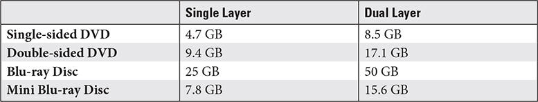
CDs come in 650-MB or 700-MB capacity, and Table 3.4-1 shows DVD and Blu-ray Disc capacities.
TABLE 3.4-1 Common DVD/Blu-ray Disc Capacities in DVD-Industry Gigabytes
Optical Speeds
Though relatively slow, newer optical drives are much faster than the first 150-KBps CD-ROM drive. Modern drives list up to three speeds (in order: read, rewrite, and write) per media using a “number times” format such as 40×. It’s simple math: to find throughput in KBps, expand 40× and multiply (40 × 150 = 6000). A CD-RW lists all three speeds in a format such as 48×32×52× (write speed, rewrite speed, read speed).
DVD drives read, write, and rewrite DVDs nine times faster than 150 KBps, so a 1× DVD drive and disc have a throughput of 1.32 MBps. DVD drives read and write CDs even faster, so they often list an extra set of CD speeds.
A 1× Blu-ray Disc drive has a speed of 4.5 MBps; Blu-ray Disc burners can write to BD-R media at speeds up to 54 MBps (12×), rewrite BD-RE discs at speeds up to 9 MBps (2×), and read BD-ROM discs as fast as 36 MBps (8×). Blu-ray Disc burners can also burn to CD and DVD media and often list three sets of speeds.
Magnetic Hard Drives
Devices that encode and decode data on magnetic media have had a long run as the dominant long-term digital data storage technology, but the writing is on the wall. Now that floppy drives and tape drives have been retired from the CompTIA A+ exams, the last magnetic media type standing is the hard disk drive.
Hard Disk Drives
Traditional hard disk drives (HDDs) store data magnetically on spinning platters, using fast-moving actuator arms with read/write heads that are controlled by a servo motor (see Figure 3.4-1). The important properties are physical size, storage capacity, spindle speed, cache size, and interface.

FIGURE 3.4-1 Inside a hard drive
Most modern HDDs are 2.5 or 3.5 inches wide and have storage capacities measured in gigabytes (GB) or terabytes (TB). HDD size relates to capacity: 2.5-inch drives, primarily used in laptops and in external storage that is powered by a USB or Thunderbolt port, presently top out around 2 TB, whereas 3.5-inch drives, used in desktop and servers and in external storage powered by an AC adapter, exceed 10 TB.
EXAM TIP Know the HDD spindle speeds and the drive categories represented.
Drives with higher spindle speed seek faster but consume more power and generate more heat and noise; Table 3.4-2 shows common HDD spindle speeds with typical use. Cache size, measured in megabytes (MB), affects the drive’s sustained throughput.
TABLE 3.4-2 Typical HDD Spindle Speeds

Hybrid Drives
Hybrid drives, also known as hybrid hard drives (HHDs) and solid-state hybrid drives (SSHDs), combine a standard HDD mechanism with a small onboard solid-state drive (SSD). Performance of hybrid drives is faster than HDDs but slower than SSDs. They are available in capacities up to 2 TB.
NOTE Computers running macOS use a somewhat similar technology called a Fusion Drive, which uses separate hard drive and SSD components. With Fusion Drive, macOS decides which information is stored in the SSD.
Solid-State Drives
The SSD, which uses flash memory chips to store data, is running the HDD out of town. SSDs weigh less, have no moving parts, seek faster, have higher throughput, consume less power, produce less heat, have better shock resistance, and last longer than HDDs. For a time HDDs retained a price and capacity advantage, but as SSDs catch up in capacity, the only advantage left is cost.
Most consumer SSDs use a SATA 2.5-inch hard drive format or an M.2 flash drive format. M.2 SSDs use two different internal data bus designs: SATA or NVMe. The original form factor used for SSDs is SATA 2.5-inch. Figure 3.4-2 compares a SATA 2.5-inch drive with an M.2 drive.

FIGURE 3.4-2 SATA (top) and M.2 (bottom) SSDs
NOTE Confused by all of the xxD acronyms yet? Hard drive and hard disk were traditionally synonyms, but in this book, aside from the term “hybrid hard drive,” we use hard drive as an umbrella term including HDD, SSD, and HHD.
M.2 Drives
M.2 drives (referred to as “M2” drives in objective 3.4) are small SSDs that are included in many laptops and tablets as well as a large number of desktop computers. The M.2 slot is used primary for SSDs, but is also used for some Wi-Fi and Bluetooth radios in some laptops.
Some M.2 drives use the SATA interface internally for data transfer, but the newest development in SSDs is NVMe.
NVMe
Non-Volatile Memory Express (NVMe) enables SSDs to run at much faster speeds than the poky SATA speeds originally developed for mechanical drives and used by SATA and standard M.2 SSDs. NVMe uses PCIe lanes for communication.
NVMe drives transfer data at 2.5–3 times the speeds of SATA and standard M.2 SSDs. They are available in either M.2 or PCIe form factors. NVMe drives are more expensive than other SSDs, but offer much higher speeds.
EXAM TIP The M.2 form factor supports both NVMe-compatible and SATA-compatible SSDs. You might encounter a question that asks about the differences, so keep in mind that NVMe is faster but doesn’t work in all M.2 slots.
Flash
Flash memory, which uses solid-state technology similar to that found in SSDs, has displaced other data storage technologies. You need to know about two flash memory families: USB thumb drives and memory cards.
USB thumb drives contain a standard USB connection, and memory card is a generic term for a number of different tiny cards that are used in cameras, tablets, and other devices. Both of these types can show up as drives in modern operating systems, but they have different jobs. USB thumb drives have replaced virtually all other rewritable removable media as the way people transfer files or keep copies of important programs.
SD Card
Many small devices such as digital cameras and smartphones store data on flash memory cards. The most popular format is Secure Digital (SD) and its smaller siblings, shown in Figure 3.4-3, mini-SD (also known as miniSD) and micro-SD (also known as microSD). Most devices support a single format, though some smaller cards fit into a converter that itself fits a larger slot. SD cards are available in capacities exceeding 2 TB.

FIGURE 3.4-3 Assortment of SD memory cards
ADDITIONAL RESOURCES To learn more about the different form factors, speeds, and capacities of SD cards, see www.sdcard.org.
Other popular formats include
• CompactFlash (CF) Capacities up to 512 GB and are used primarily in professional digital SLR cameras. CF cards are also available for network and other non-storage applications.
• Extreme Digital (xD) Picture Card xD Picture Card memory cards have capacities up to 2 GB. They were used by many older Olympus and Fujifilm cameras, but have been replaced by other formats, most notably SD.
EXAM TIP Be familiar with the differences between SD, CF, and xD cards, including capacities, smaller versions, and current uses.
Installing Storage Devices
There are two types of interfaces used for internal storage devices on recent systems: SATA and M.2. The following sections explain how to install devices that use these interfaces.
Installing SATA Drives
There used to be a few catches when installing SATA drives; these days, just connect the power, plug in the controller cable (see Figure 3.4-4), and wait for the OS to automatically detect the drive. The keying on SATA controller and power cables makes it impossible to install either incorrectly.

FIGURE 3.4-4 Properly connected SATA cables
Since motherboards come with many SATA connectors, how does the system find the right hard drive to boot up to? That’s where the BIOS/UEFI settings come into play. By default, boot order and drive letter priority follow SATA controller ID: SATA 0 is C:, SATA 1 is D:, and so on.
EXAM TIP BIOS/UEFI setup utilities enable you to change boot order easily, which is great for multi-OS computers.
When installing optical drives, you might also need to install movie playback apps supplied with some drives. The SATA interface works the same way with any type of SATA drive.
NOTE If you need to install an IDE drive, each drive on the cable (which supports up to two drives) needs to be jumpered using a small block on the rear or bottom of the drive. With an 80-wire cable, jumper all drives as CS (cable select). With two drives on the older 40-wire cable, one should be jumpered as MA (master) and the other as SL (slave). If there is only one drive on a 40-wire cable, see the drive’s documentation for details.
Installing M.2 Drives
With any type of M.2 device, including standard SSDs, NVMe SSDs, or other types of M.2 devices used in laptops, the selection and installation processes have these steps:
1. Select a device that fits into the slot.
2. Secure the device with a mounting screw.
All M.2 cards are 22 mm wide, with lengths varying from 30 mm to as much as 110 mm. The most common size, however, is 2280 (22 mm wide, 80 mm long), as illustrated in Figure 3.4-5.
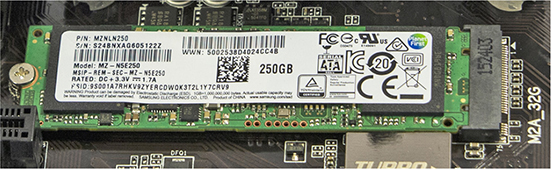
FIGURE 3.4-5 An M.2 2280 SSD installed and secured into an M.2 slot
Configurations
The CompTIA A+ 220-1001 exam also expects you to know about two special drive configurations: RAID and hot-swapping. See the following sections for details.
RAID 0, 1, 5, 10
A redundant array of independent (or inexpensive) disks (RAID) uses multiple hard drives to increase performance and protect data. Motherboards with built-in RAID controllers may have a BIOS/UEFI setting to enable or disable RAID (see Figure 3.4-6).
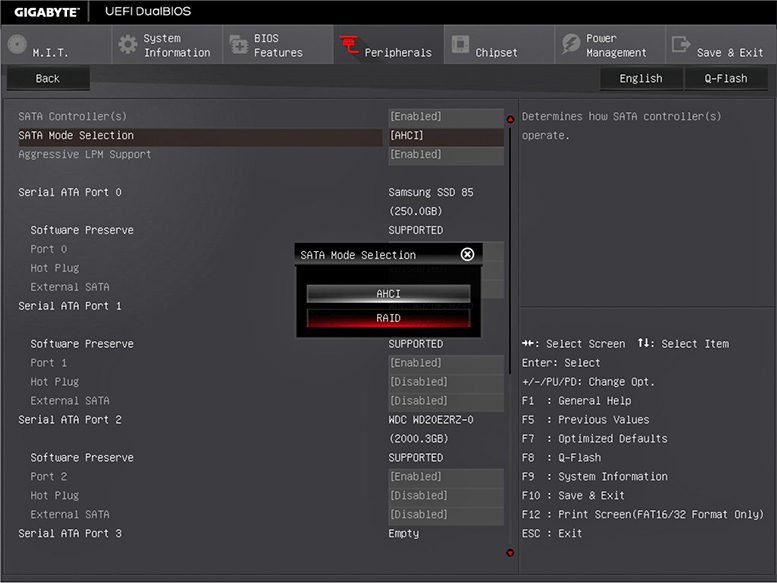
FIGURE 3.4-6 Settings for RAID in a UEFI BIOS
EXAM TIP A RAID array collects two or more hard drives into a logical unit. CompTIA expects you to know RAID levels 0, 1, 5, and 10.
RAID 0: Disk striping Disk striping requires at least two drives. It increases performance by splitting work over multiple drives, but it does not provide redundancy to data. If any drive fails, all data is lost.
RAID 1: Disk mirroring/duplexing RAID 1 arrays require at least two hard drives, although they also work with any even number of drives. RAID 1 mirrors data across multiple drives, providing safety at the cost of storage space (since data is duplicated; you need two 2-TB drives to store 2 TB of data).
RAID 5: Disk striping with distributed parity RAID 5 distributes data and parity information evenly across all drives. This is the fastest way to provide data redundancy. RAID 5 arrays effectively use one drive’s worth of space for parity, requiring a minimum of three drives. In RAID 5, three 2-TB drives provide a capacity of 4 TB, while four 2-TB drives provide a capacity of 6 GB.
RAID 10: Nested, striped mirrors RAID 10 takes two mirrored pairs of drives and stripes them together. This creates an array with excellent speed and redundancy, though it takes four drives as a minimum. RAID 10 is not one of the original RAID levels, but is fairly common today.
EXAM TIP RAID 0 and 1 can be combined. Mirroring two striped-drive pairs results in RAID 0+1. Striping two mirrored-drive pairs produces RAID 1+0, or RAID 10. Arrays combining single RAID types are called multiple RAID solutions or nested RAID.
Windows 8 and later include a tool called Storage Spaces that enables you to create a number of RAID-like array varieties via software. We’ll cover Storage Spaces in Part II, Domain 1.0, for CompTIA A+ 220-1002 exam candidates.
EXAM TIP JBOD stands for just a bunch of disks (or drives). It’s a storage system with multiple independent disks, rather than RAID-organized disks. It provides no redundancy and no performance increase. You might encounter a question that contrasts JBOD with RAID, so make sure you understand the differences.
Hot Swappable
A hot-swappable drive will be recognized even if it is connected, swapped, or replaced while the system is running. SATA drives that are configured as Advanced Host Controller Interface (AHCI) drives or hardware RAID in the system BIOS or UEFI firmware are hot-swappable, as are eSATA, USB, and Thunderbolt drives.
REVIEW
Objective 3.4: Given a scenario, select, install, and configure storage devices
• Optical discs are available in CD, DVD, and BD (Blu-ray) types.
• RW and RE discs are rewriteable.
• R discs are recordable.
• ROM discs are read-only.
• BD drives can also use DVD and CD media.
• DVD drives can also use CD media.
• Optical speeds are rated differently according to the media type, using the order write, rewrite, and read.
• SSDs are rapidly replacing HDDs for primary storage.
• A hybrid hard drive combines a small SSD with a larger HDD.
• SATA HDD, SSD, and optical drives are installed using a SATA data cable and a SATA power cable.
• M.2 drives are available in conventional (SATA SSD speed) and NVMe (2.5 to 3 times faster) types.
• M.2 drives are installed using a mounting screw provided with the motherboard that holds the drive in place and are available in various form factors, of which 2280 (22-mm wide, 80-mm long) is the most common.
• HDDs are available in 3.5-inch or 2.5-inch form factors.
• HDDs have spindle speeds of 5400 RPM, 7200 RPM, 10000 RPM, and 15000 RPM.
• 3.5-inch drives are used in AC-powered enclosures or desktops and servers.
• 2.5-inch drives are used in USB-powered enclosures or laptops.
• The most common family of flash memory cards is SD, including mini-SD and the very popular micro-SD.
• CompactFlash cards are used primarily in professional-level digital SLR cameras.
• xD cards (xD-Picture Card) were used by older Fujifilm and Olympus digital cameras.
• RAID 0 is faster than other RAID types because data is striped across two drives; it has no redundancy.
• RAID 1 mirrors the contents of one drive to the other.
• RAID 5 uses at least three drives and distributes data and recovery (parity) information across all drives.
• RAID 10 combines striping and mirroring (requiring four drives).
• Hot-swappable drives can be replaced without shutting down the system. USB, Thunderbolt, and SATA drives configured as AHCI or hardware RAID all support hot-swapping.
3.4 QUESTIONS
1. Your client is planning to replace 500-GB hard disks with similarly sized SSDs. Assuming compatibility, which of the following would provide the best performance?
A. NVMe 2.5-inch
B. NVMe M.2
C. SATA M.2
D. SATA 2.5-inch
2. Which of the following correctly ranks SATA drive types in order from slowest to fastest?
A. 5400 RPM, SSHD, 7200 RPM, SSD
B. 7200 RPM, 5400 RPM, SSD, SSHD
C. 5400 RPM, 7200 RPM, SSHD, SSD
D. SSD, SSHD, 5400 RPM, 7200 RPM
3. Your client wants to add an NVMe drive to its desktop systems to boost performance, but the M.2 slots in these systems don’t support NVMe drives. Which of the following interfaces can be used instead?
A. SATA
B. PCIe
C. SATA
D. ISO 9660
4. Your client wants to choose a RAID array type that offers excellent speed and reliability. Which of the following is the best match for this requirement?
A. RAID 10
B. RAID 1
C. RAID 5
D. RAID 0
5. Your client accidentally purchased a micro-SD card for her digital camera instead of an SD card. Which of the following is the best way to use the card?
A. Copy the data from an existing card to the new card
B. Return the card to the store for the correct type
C. Use an adapter with the card
D. Buy a new camera that uses micro-SD cards
3.4 ANSWERS
1. B The NVMe M.2 SSD is the fastest type of SSD.
2. C 5400 RPM is the slowest SATA drive, 7200 RPM is faster, SSHD is faster, and SSD is fastest.
3. B NVMe drives are available in PCIe cards; NVMe uses the PCIe bus for extra speed over SATA.
4. A RAID 10 combines mirroring for data protection and striping for speed.
5. C SD adapters for micro-SD cards are very common, and are often bundled with micro-SD cards.
Objective 3.5 Given a scenario, install and configure motherboards, CPUs, and add-on cards
Custom PC configurations and upgrades rely on a tech’s ability to integrate off-the-shelf components from various sources into a working system. In this objective, you learn how to choose, install, and configure compatible motherboards, CPUs, and add-on cards.
Motherboard Form Factor
A form factor defines the motherboard’s size, orientation, location of built-in sockets and expansion slots, and so on. Most motherboards come in either of two form factors, ATX or ITX, though you’ll probably see proprietary form factors as well. Each form factor has a few varieties. Form factors are not interchangeable, and they determine the type of power supply and case a computer can use; ATX motherboards fit into ATX cases, and ITX motherboards fit into ITX cases.
ATX
In 1995, Intel introduced the ATX motherboard form factor (see Figure 3.5-1) to replace the aging AT form factor originally developed by IBM. The ATX form factor rearranged expansion slots, CPU, and RAM for easier access and enhanced performance, and to prevent long expansion cards from colliding with the CPU (a common problem in AT systems).
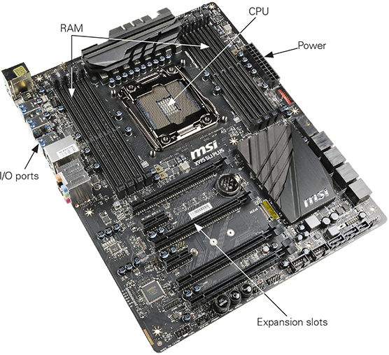
FIGURE 3.5-1 ATX motherboard
ATX motherboards collect ports for built-in peripherals at an I/O panel on the back of the case known as a port cluster. A sheet metal I/O shield with cutouts and labels for the ports typically covers any unused space. Figure 3.5-2 illustrates a typical port cluster from a recent system.
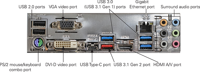
FIGURE 3.5-2 Typical ATX port cluster
There have been several revisions of the ATX standards over the years. The more notable changes are new power connectors for modern, power-hungry motherboards, and updated recommendations for power supply fans and airflow.
The most common versions of ATX are full-sized ATX (12 by 9.6 inches) and microATX (9.6 by 9.6 inches, also known as mATX). MicroATX shares the power connectors and basic layout with ATX but are scaled for much smaller cases. Full-sized ATX motherboards will not fit into microATX cases, though most full-sized cases support the smaller motherboards.
EXAM TIP Know that ATX is a full-sized motherboard (up to seven slots) for full-sized cases and mATX is a smaller version of ATX with up to four slots that fits into smaller or full-sized ATX cases.
ITX
VIA Technologies created the standard for the current leader in small form factor (SFF) motherboards: ITX. Although the full-sized ITX design flopped, VIA created smaller form factors that fared better: Mini-ITX, Nano-ITX, and Pico-ITX.
Mini-ITX (mITX) is the largest and the most popular, and at a miniscule 6.7 inches square, it competes with the much larger microATX (see Figure 3.5-3). For comparison, microATX motherboards are 9.6 inches square.
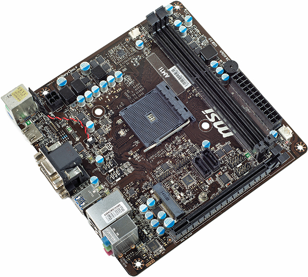
FIGURE 3.5-3 Mini-ITX
If you think that’s small, Nano-ITX at 4.7 inches square and Pico-ITX at 3.8 by 2.8 inches are even smaller. These tiny motherboard form factors are commonly used for embedded systems and specialized devices such as routers.
EXAM TIP ITX is the original, defunct version of the smaller and much more popular Mini-ITX (mITX) motherboard.
Motherboard Connectors Types
Motherboards are more than the home of RAM and CPUs. Storage, video, I/O, and other types of devices are also connected to the motherboard, as you learn in the following sections. These devices are connected to each other through the slots, wires, and support chips built into the motherboard and are collectively known as the expansion bus.
PCI
Intel introduced the Peripheral Component Interconnect (PCI) bus architecture in the early 1990s and released it into the public domain to attract manufacturers. The original PCI bus was wider (32 bits), faster (33 MHz), and more flexible than any previous expansion bus, and its self-configuration feature led to the plug and play (PnP) standard. The exceptional technology and its lack of a price tag led manufacturers to quickly replace earlier busses with PCI.
PCIe
PCI Express (PCIe) is the latest, fastest, and most popular expansion bus in use today. PCI Express is still PCI, but it uses a point-to-point serial connection instead of PCI’s shared parallel communication. The serial interface reduces transfer overhead and supports higher speeds without causing interference to other parts. A PCIe device’s direct (point-to-point) connection to the northbridge means it does not wait for other devices.
A PCIe lane uses a wire each to send and receive. Better yet, each connection can use 1, 2, 4, 8, 12, 16, or 32 lanes with corresponding slots referred to as ×1, ×4, etc. Each direction of a lane runs at the following speeds depending upon the PCIe version supported by the card or device and the motherboard:
• PCIe 1.0: 2.5 gigatransfers per second (GTps)
• PCIe 2.0: 5.0 GTps
• PCIe 3.0: 8.0 GTps
• PCIe 4.0: 16.0 GTps)
NOTE Pronounce lanes as “by” rather than “ex.” So “by 1” and “by 16” are the correct pronunciations of ×1 and ×16.
In case of a mismatch between versions supported by the slot and the card, the slower standard is supported.
NOTE A lot of laptop computers offer an internal PCIe expansion slot called PCI Express Mini Card, or Mini PCIe. It works like any PCIe expansion slot, though it’s not compatible with full-sized cards.
The most common PCIe slot is the 16-lane (×16) version most video cards use, while ×1 and ×4 are the most common general-purpose PCIe slots. The first PCIe motherboards used a single PCIe ×16 slot and several standard PCI slots. Figure 3.5-4 compares PCIe and PCI slots on a typical late-model motherboard.
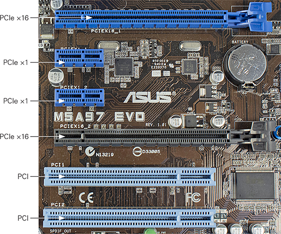
FIGURE 3.5-4 PCIe ×16, ×1, and PCI slots
EXAM TIP Given a scenario, be able to identify the various PCI and PCIe slots.
Riser Card
One feature you’ll see in proprietary motherboards is a special riser card (see Figure 3.5-5), also called a daughter board—part of a motherboard separate from the main one, but connected by a cable of some sort or a right-angle connector that plugs into a slot. Proprietary motherboards also have unique power connections. Proprietary motherboards, though rare today, drive techs crazy because replacement parts tend to cost more and are not readily available.
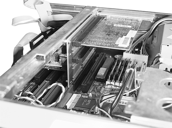
FIGURE 3.5-5 Riser card on an older motherboard
Socket Types
Most desktop motherboards use sockets to accommodate different CPU models, although a few have soldered-in-place CPUs. AMD and Intel CPUs use different sockets and different internal architectures, so their CPUs are not interchangeable.
Cross-Reference
SATA
SATA connectors on motherboards might face upward or be positioned along the front edge to face forward. Some motherboards feature ports in both positions (see Figure 3.5-6).

FIGURE 3.5-6 Front-mounted and top-mounted SATA ports on a typical motherboard
IDE
Motherboards built during the transition from IDE to SATA have both types of ports (see Figure 3.5-7).

FIGURE 3.5-7 SATA ports compared to an IDE port on a motherboard
Front Panel Connector
The front panel connector (see Figure 3.5-8) is used for wires such as the case power switch, power and drive activity signal lights, reset button, and more.

FIGURE 3.5-8 USB 2.0 headers, a USB 3.0 header, and a front panel connector on a typical late-model motherboard
Internal USB Connector
Internal USB connectors are available in two common form factors: a USB 2.0 header is a 9-pin rectangular connector that supports two USB 2.0 ports, and a USB 3.0 header is a 19-pin rectangular connector that supports two USB 3.0 ports. Both are shown in Figure 3.5-8 along with a typical front panel connector.
NOTE A USB Type-C header is considerably smaller than a USB 3.0 (USB 3.1 Gen 1) header and uses a special cable that supports a single port.
Installing a Motherboard
When you install a motherboard, follow these guidelines:
1. Be sure to take precautions against ESD. Remember that it’s very easy to damage or destroy a CPU and RAM with a little electrostatic discharge. It’s also fairly easy to damage the motherboard with ESD. Always wear your anti-static wrist strap.
2. Make sure the case’s brass standoff spacers match the mounting holes on the motherboard. You might need to unscrew some of them and move them around or add additional spacers.
3. Install the CPU and heat sink/fan, and RAM before you install the motherboard, to avoid cracking the motherboard.
4. Line up the I/O shield that fits between the hole for the port cluster and the motherboard from the inside of the case before fastening the motherboard into place. The ports in the port cluster will help to hold the shield in case.
5. Before fastening the motherboard into place, connect front-panel wires, fans, and front-mounted port cables. These might be difficult to access after the motherboard is secured in place.

CAUTION Make sure the standoffs on the bottom of the case line up with the mounting holes. Remove any excess standoffs. Standoffs that touch the wire traces or solder points on the bottom of the motherboard will short out the motherboard when the power is turned on.
6. Fasten the motherboard into place using the appropriate screws. If possible, use a hex driver instead of a Phillips-head screwdriver to avoid tool slippage. A scratched motherboard might fail.
BIOS/UEFI Settings
The CMOS setup utility stored in the system ROM enables you to configure important system BIOS settings stored in the CMOS chip, which is built into the chipset on most computers. These settings include CPU setup, boot sequence, power management, and a number of others, as described here.
BIOS/UEFI
The system BIOS chip is a ROM chip that stores the system BIOS routines and CMOS setup utility. Because these are software routines that are stored on a chip, the system BIOS is an example of firmware. System ROM is often distinctively labeled with the BIOS maker’s name, but can also appear as a tiny chip on the motherboard.
There’s a big difference between system ROM chips and RAM: RAM is called volatile because it stores data only while the computer is powered. System ROM is non-volatile and retains data even when the system is not powered. Except for replacing the CMOS battery (described in the next section) if it dies, system ROM requires no specific maintenance.
The firmware on modern systems is the Unified Extensible Firmware Interface (UEFI). Here are the essentials:
• UEFI is often associated with graphical system setup utilities, whereas traditional BIOS is associated with text-mode utilities—even on the CompTIA A+ 220-1001 exam. However, this isn’t a given. You can find graphical BIOS utilities and text-mode UEFI utilities.
• UEFI supports booting to partitions larger than 2.2 TB.
• Unlike with BIOS, the UEFI setup utility can be opened from within the OS.
• UEFI supports a security feature called Secure Boot that ensures a device boots using only trusted software.
Entering the CMOS Setup Utility
With a traditional BIOS, you can’t enter the CMOS setup utility from within the OS; you must do it early in the boot process. Methods differ by maker, but instructions for entering CMOS usually appear on your monitor during bootup (see Figure 3.5-9). Watch the messages carefully or check your motherboard documentation on which key to press.
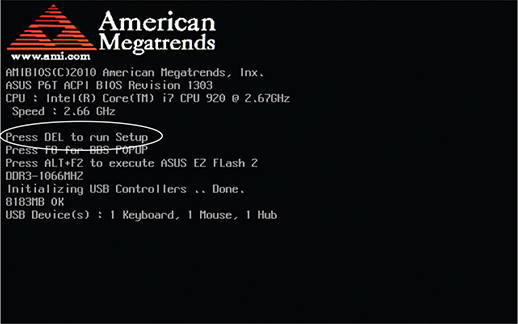
FIGURE 3.5-9 Each BIOS maker provides instructions for entering CMOS at bootup.
Navigating the CMOS Setup Utility
Mouse-friendly graphical setup utilities are increasingly common, but if you find yourself in a text-mode utility, you’ll navigate with the keyboard. Both interface styles typically open to a screen with information about your system, components, and settings (see Figure 3.5-10); this interface provides a good overview of your CPU, RAM, hard drives, and optical drives. Navigation instructions may vary but should be prominently displayed. Usually the ARROW keys move the cursor and the ENTER key makes selections. If you get stuck, press the F1 key to bring up a Help menu.
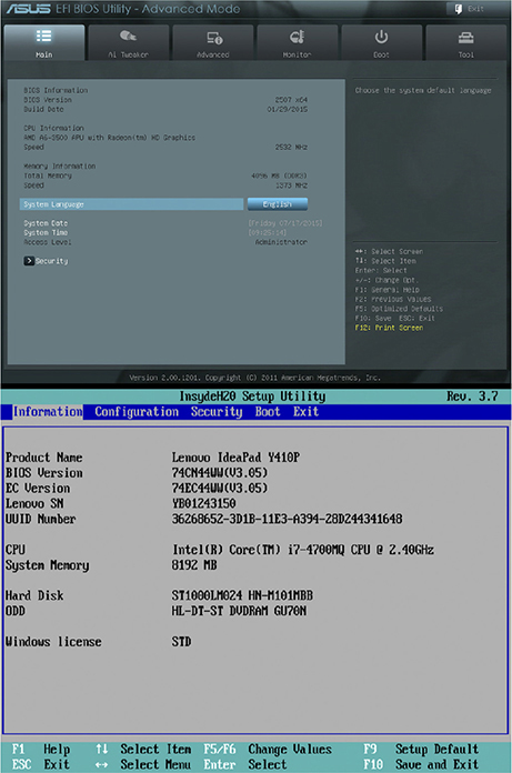
FIGURE 3.5-10 System information screen in graphical (top) and text-mode (bottom) setup utilities
Even though Figure 3.5-10 shows you can’t count on tab names being the same on different utilities, there are still many common settings and organizational patterns that will help you to find your way. Before we dive in, there are two more navigation features to keep in mind before you decide to exit the system setup utility:
• Save & Exit Setup To avoid accidents, only use this option when you intend to make a change and you’re absolutely certain what the effect will be. Typically, selecting this option brings up a confirmation prompt such as “Are you sure you want to make these changes? Y/N.”
• Exit Without Saving This option discards your changes. Choosing this option brings up another “Are you sure? Y/N” confirmation prompt. Press Y to take your leave of CMOS setup without doing any damage.
NOTE There’s enough variety in how tabs, menus, and options are labeled in different setup utilities that you’ll inevitably find yourself hunting for what you need.
Boot Options
The boot options (see Figure 3.5-11 for an example) hold one of the most frequently changed settings in the setup utility: the boot sequence. This setting decides which devices your system attempts to boot from and in what order. Other options you’re likely to find here dictate whether the system boots from USB devices or network locations, displays detailed POST information, displays the key combination to reach the setup utility, and so on.

FIGURE 3.5-11 Boot tab in graphical setup utility
EXAM TIP The boot sequence is the first place to check if you have a computer that attempts to boot to an incorrect device or gives an “invalid boot device” error. If you have a USB thumb drive inserted and this CMOS setting has removable devices ahead of hard drives in the boot order, the computer will dutifully try to boot from the thumb drive.
Firmware Updates
Techs refer to firmware updates, or updating system BIOS, as flashing the BIOS. It’s a simple procedure, but it must be done correctly and without interruption: an interrupted BIOS flash usually renders the motherboard useless. Before flashing your BIOS, back up your important documents and update any system repair media. Make certain the process isn’t disturbed once you start.
EXAM TIP The CompTIA A+ 220-1001 exam refers to flashing the BIOS as a firmware update.
Some motherboards come with a Windows-based utility that will go to the Web, download an updated BIOS, and enable you to flash the BIOS from within Windows. When it works, it’s sweet. Otherwise, BIOS makers provide flashing utilities on their websites.
Interface Configurations
Some of the interface settings available in typical BIOS/UEFI firmware settings include
• Enable/disable ports (SATA, USB, Serial-RS-232, network, audio)
• Configure SATA settings: AHCI supports hot-swapping and full features; RAID supports RAID configurations and hot-swapping; IDE accesses drives in IDE mode (slower, no support for hot-swapping)
Security and Security Settings
CompTIA wants you to know about several security options you might find in the setup utility, whether collected on a single tab (see Figure 3.5-12) or scattered about other menus:
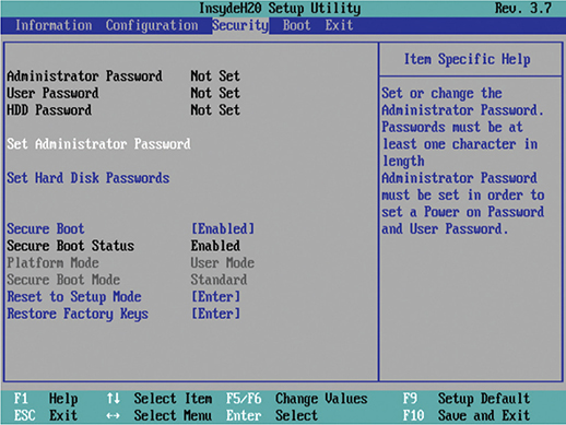
FIGURE 3.5-12 Security tab in text-mode setup utility
• Passwords When a user CMOS password is set, the system won’t boot without the correct password. An administrator CMOS password restricts access to the CMOS utility itself.
EXAM TIP Remember that CMOS settings—including passwords—can be wiped via the CMOS clear jumper or button, or by removing and replacing the CMOS battery.
• Chassis intrusion detection/notification Most new systems have an option in CMOS that reports when the side of the case is opened, alerting techs to potential tampering.
• Drive Protection Drive protection, which helps protect the system drive from unauthorized use, can be incorporated into the BIOS/UEFI firmware. Three common types include
• Trusted Platform Module The Trusted Platform Module (TPM) acts as a secure cryptoprocessor: a hardware platform for accelerating cryptographic functions and securely storing the associated information in tamper-resistant hardware. A common use of TPMs is accelerating and securing hard drive encryption, such as the BitLocker Drive Encryption feature of Microsoft Windows.
• LoJack If you have a LoJack-equipped computer that is stolen, LoJack enables you to track its location, install a key logger, or even remotely shut down the system.
• Secure Boot This UEFI protocol protects the system from some low-level malware and other exploits by refusing to load driver or OS software that hasn’t been properly signed by a trusted party. Secure Boot requires an Intel CPU, a UEFI BIOS, and an operating system designed for it.
EXAM TIP Be able to distinguish between the TPM, LoJack, and Secure Boot drive protection options for the CompTIA A+ 220-1001 exam.
CMOS Battery
Every motherboard has a CMOS battery that enables it to retain CMOS settings when disconnected from external power. CMOS batteries fail gradually. If you notice your system clock running slow, or if you’re consistently prompted to enter the date and time when you boot the PC, it’s time to replace the CMOS battery. Replacing the CMOS battery (see Figure 3.5-13) is simple: slide the old one out of the bracket and slip a new one with matching voltage in its place. The real-time-clock (RTC) on the motherboard is also maintained by the CMOS battery.

FIGURE 3.5-13 CMOS battery
CPU Features
CPUs have a variety of features that distinguish them from each other, including the number of cores, support for virtualization, Hyper-Threading, clock speeds, overclocking support, and integrated GPUs, as you learn in the following sections.
Hyper-Threading
CPUs can handle multiple processes—opening a file, playing an MP3, and so on—nearly simultaneously by switching rapidly back and forth between threads, the subunits that make up a process. Many processes have only one thread, but some processes have many threads.
Hyper-Threading Technology is Intel’s implementation of simultaneous multithreading, which executes multiple threads simultaneously on a single processor core to increase performance. A multithreaded processor looks like more than one CPU to the OS, but it’s limited by having just one set of CPU resources. AMD’s version of multithreading is simply known as simultaneous multithreading (SMT).
EXAM TIP Be sure to understand the difference between Hyper-Threading Technology/SMT (in which one processor core supports multiple threads) and multicore processors (in which each CPU has two or more processor cores).
Single-core and Multicore
Originally, all CPUs had a single processor core. CPU clock speeds hit a practical limit of roughly 4 GHz around 2002, motivating the CPU makers to combine multiple CPUs onto the same physical processor die, creating multicore CPUs. The first batch of multicore processors combined two CPU cores onto one chip, creating a dual-core architecture.
Unlike Hyper-Threading, where a single processor core shares execution resources among threads, a true dual-core CPU has two discrete processor cores, each possessing its own resources. Today’s CPUs often have eight or more (see Figure 3.5-14). Most modern multicore processors also support Hyper-Threading Technology or SMT, so each core can handle multiple threads.
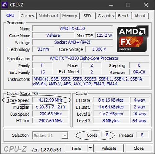
FIGURE 3.5-14 CPU-Z showing an AMD FX-8350 with eight cores and clock speed highlighted
Virtualization
Intel and AMD have built-in support for virtualization, a process that enables you to run one or more virtual computers on a single hardware computer. Early virtualization worked entirely through software. Programmers had to write a ton of code to enable a CPU designed to run one OS at a time to run more than one OS, but hardware-based virtualization enables the CPU to take on most of this burden. Virtualization is enabled through the BIOS/UEFI firmware.
Cross-Reference
Speeds
The CPU clock speed, or frequency, tells you how many calculation cycles a CPU can theoretically execute per second. One calculation cycle per second is equal to 1 hertz (Hz), but nobody measures clock cycles in hertz. Instead, we use millions or billions of calculation cycles per second, respectively called megahertz (MHz) or gigahertz (GHz), such as 1 GHz, which equals 1 billion cycles per second.
Two things determine clock speed: the maximum speed of the CPU itself and what the motherboard can handle. The CPU speed is determined by the manufacturer and set at the factory. The system crystal—a quartz crystal circuit that oscillates at a fixed frequency when fed current—sets the motherboard’s clock speed.
Modern CPUs run at a multiple of the system clock speed. The system bus on my 4.1-GHz FX-8350 system runs at 200 MHz, so the clock multiplier goes up to ×20.5 at full load to support the maximum speed. Early CPUs ran at the speed of the bus, but engineers realized the CPU was the only thing working much of the time; if they could speed up just the CPU, they could speed up the whole process.
Old motherboards used jumpers to set the system bus speed and clock multiplier, but today’s CPUs report to the motherboard via CPUID (CPU identifier) so the system bus speed and multiplier can be set automatically. Many motherboards offer manual configuration for tweaking systems.
Overclocking
Some motherboards enable you to adjust CPU settings manually by changing a UEFI/BIOS setting or using other software; CPUs vary in their support for changes. Many enthusiasts practice overclocking: deliberately changing these settings to run their systems at clock speeds higher than the CPU rating, to enhance performance. A successful overclock usually takes two adjustments: increasing the system’s bus speed, and increasing CPU voltage a little to provide stability. Always do only one thing at a time, document your change, and then reboot.
In addition to the slight risk of overheating, unstable CPU settings can make the UEFI/BIOS settings unreachable. Most motherboards have a button or jumper setting called CMOS clear (see Figure 3.5-15) that resets UEFI/BIOS to default settings. Before you try overclocking, find CMOS clear and know how to use it. Always follow manufacturer recommendations and warranties before overclocking.
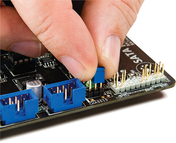
FIGURE 3.5-15 Using the clear CMOS jumper
CAUTION Overclocking might also make your system prone to system lockups, reboots, and unexpected shutdowns. Overclocking typically voids equipment warranties. Be careful!
Integrated GPU
Computers traditionally have a discrete special-purpose microprocessor designed for video processing, known as a graphics processing unit (GPU). Because graphics processors handle some tasks more efficiently than a standard CPU, integrating a GPU into the CPU enhances the overall performance of the computer and reduces its energy use, size, and cost.
Intel and AMD design their integrated GPUs a little differently. The Intel HD Graphics integrated into many Core i3/i5/i7/i9 processors, for example, has the CPU cores and the GPU core sharing the “last level cache,” which is either L2 or L3, depending on the processor. With the AMD accelerated processing unit (APU), such as the AMD Ryzen, the GPU has access to all levels of cache on the CPU.
CPU Compatibility
Since no processors work in all motherboards, you should check the motherboard’s documentation (or its manufacturer’s website) for a chart listing the CPUs it supports. Because Intel and AMD CPUs are not pin-compatible, motherboards made since the mid-1990s support either Intel CPUs or AMD CPUs—not both. The type of CPU socket that the motherboard uses determines which model of Intel or AMD CPU you can install. Many motherboards accept more than one model of CPU. Likewise, some CPU models can fit more than one socket. Table 3.5-1 provides a reference to the Intel desktop processor sockets you’re likely to encounter in the field, and Table 3.5-2 provides a reference to the AMD sockets you’re likely to encounter in the field. Both vendors use zero insertion force (ZIF) sockets to hold the sockets in place.
TABLE 3.5-1 Intel-based Sockets and Processors

TABLE 3.5-2 AMD-based Sockets and Processors

ADDITIONAL RESOURCES To learn more about specific Intel CPU sockets and supported processors, see the Intel ARK website at http://ark.intel.com. To learn more about specific AMD CPU sockets and supported processors, see the AMD website at www.amd.com.
EXAM TIP Because the CompTIA A+ exam has had pin-related questions in the past, Table 3.5-2 includes the pins for the AMD sockets. Intel socket names identify the number of pins associated with those sockets.
Cooling Mechanism
CPUs have no moving parts (that you can see with the naked eye), but they generate considerable heat. Excessive heat causes system instability, lockups, and dead CPUs. CPU packages are made from high-tech thermal plastics and ceramics that dissipate heat, but they still can’t provide enough relief without help. This help comes in the form of active cooling via heat sink and fan assemblies (see Figure 3.5-16) and liquid cooling systems.

FIGURE 3.5-16 Top of retail heat sink (left) and bottom of fan assembly (right) for an Intel CPU
Installing a Heat Sink and Fan Assembly
Unlike the CPU socket, mounting heat sink and fan assemblies properly takes more force than you’d expect! A small flathead screwdriver will help.
EXAM TIP Some systems get by on fanless or passive cooling. Smartphones and tablets are the passively cooled devices you’re most likely familiar with. Passive CPU heat sinks may still rely on other fans to create good airflow in the case.
Some systems use a passive heat sink assembly instead of a heat sink plus fan. These systems generally have very low-power processors that produce very little heat, such as an Intel Celeron or Atom.
Heat sink and fan assemblies for CPUs usually come as a unit; if not, attach the fan to the heat sink before installing both onto the CPU. Again, different CPUs, socket designs, and heat sinks require different installation procedures, so be sure to read the documentation. The general steps for installation are as follows:
1. If your CPU has thermal paste preapplied, remove and discard the protective tape. If not, apply a very thin film of thermal paste to the raised center of the CPU package, as shown here:
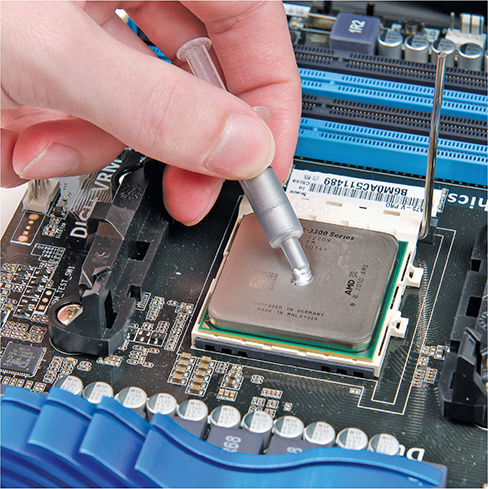
2. Align the heat sink and fan assembly’s mounting bracket hardware with the mounting notches on the CPU socket.
3. With Intel stock fans, push the mounting pins in until they click in place. It’s easy with the motherboard outside the case. Support the motherboard with one hand and push with the other so the motherboard does not flex.
4. For AMD fans, attach the mounting bracket to one side of the CPU socket unless you’re installing a Wraith cooler. For these coolers, remove the mounting clips at each side of the socket.
5. Rotate the built-in locking lever on the opposite side to secure the assembly, as shown next. On a Wraith cooler, fasten the screws on the corners of the fan assembly into the mounting holes used by the mounting clips.

6. Finally, plug the fan’s power cable into the appropriate socket or header on the motherboard. Check your motherboard documentation for information.
Thermal Paste
Thermal paste, also known as thermal interface material (TIM), must be used between a fan and heat sink, a passive heat sink, a liquid cooling element, and the top of a CPU. OEM fan and heat sink units often include preapplied TIM that is protected with tape. The tape must be removed before installing the fan and heat sink. Otherwise, the installer must provide thermal paste and apply a thin, even coating to the top of the CPU before installing the cooling device.
Installing a Liquid Cooling System
The essential installation steps for modern liquid cooling systems are similar:
1. Follow the manufacturer’s instructions to attach the hoses from the coolant reservoir tank to the CPU cooling element and the heat exchanger unit. Confirm that all hoses are secure and crimped properly.
2. Fill the coolant reservoir with the recommended amount of distilled water.
3. Apply a small amount of thermal compound to the CPU.
4. If your liquid cooling system uses a separate CPU temperature sensor on the cooling element, attach it to the appropriate slot or groove and secure it with the supplied metal tape. Mount the cooling element to the CPU with the attached bracket and secure it in place with the tension screw (see Figure 3.5-17). Be careful not to overtighten the screw. You’re ready to go!

FIGURE 3.5-17 Cooling element mounted on CPU
Expansion Cards
Although today’s systems have many built-in ports, adding expansion cards is often necessary to provide better video performance or to add features. Although the following sections are written for Windows installations, expansion cards are also supported by macOS and Linux systems.
Video Cards
A video card (or display adapter) handles the video chores within computing devices, processing information from the CPU and sending it to the display. It is configured the same way whether it is onboard (GPU built into the CPU) or an add-on card. When installing a card in Windows, you must install drivers and use Device Manager to confirm that it works. Then, you configure the video card in the Display Control Panel applet or with included software (see Figure 3.5-18).
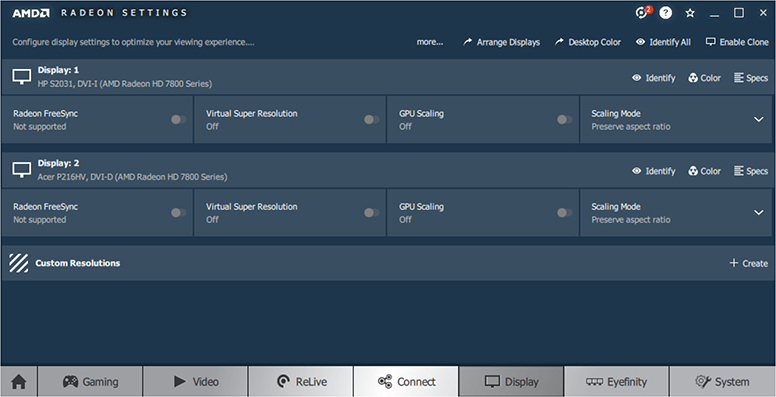
FIGURE 3.5-18 The Display dialog box from AMD Radeon Display Settings
Onboard
An onboard video card uses the built-in graphics processing unit (GPU) found in many CPUs. Almost all laptops use onboard graphics, as well as most thick and thin client desktops. Desktop computers that support CPUs with onboard GPUs have one or more video card ports in the port cluster on the rear of the computer (refer to Figure 3.5-2 for a typical example).
Add-on Card
A video card that goes into a PCIe slot, an add-on card in CompTIA terminology, probably needs additional power beyond what the slot itself provides. Midrange PCIe video cards use a 6-pin PCIe power connector on the top front edge of the video card (the end pointing away from the card bracket), while high-end cards use an 8-pin version or, in some cases, two PCIe cables. Figure 3.5-19 illustrates a PCIe video card with a 6-pin power connector and a 6/8-pin PCIe power cable.
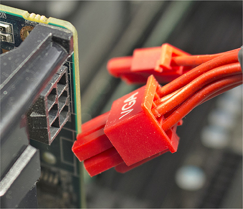
FIGURE 3.5-19 Connecting a PCIe power cable to a PCIe video card
The main parts of a video card are video RAM and a video processor. The video processor takes information from the video RAM and shoots it out to the monitor. Early video processors were little more than an intermediary between the CPU and video RAM, but powerful modern video cards need fans to cool their video processors (see Figure 3.5-20).
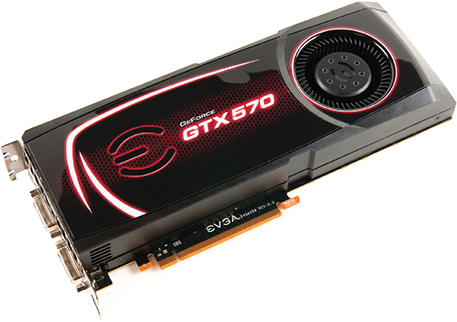
FIGURE 3.5-20 Video card with a cooling fan
Among techs, video card discussions revolve around the GPU and RAM used. The two major GPU makers, NVIDIA and AMD, develop and sell new GPUs to card manufacturers. Let’s break down a typical card name: Asus EX-RX570-O8G. Asus is the card manufacturer, RX570 is a GPU made by AMD, and O8G refers to the 8 GB of onboard memory. For more information about a card, look up the card on the vendor’s website.
Low-end graphics processors are enough to write letters or run a web browser, but high-end graphics processors support intensive uses such as beautiful 3-D games, graphics rendering (3-D, animation, video), and even certain kinds of data processing (scientific research, for example) that GPUs are well suited for. Don’t be shocked if someone who knows zilch about the latest games needs a system with one or more high-end GPUs—don’t skimp on their hardware, and don’t assume they need a GPU tailored to gaming.
Sound Cards
Sound output is generated by the sound card and speakers. Most computers use sound chips built into the motherboard, but these often have an audible hum or buzz of interference from the rest of the motherboard (which headphones can exacerbate). In any case, speakers affect customer satisfaction much more than the sound card or built-in sound chips. Spend a little extra money to get decent speakers. If you can fit only a 2.1 set, go for a subwoofer and nice satellites (see Figure 3.5-21).
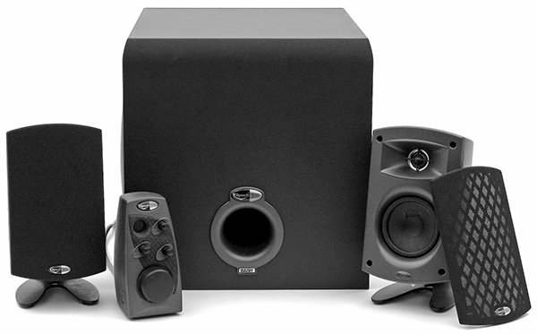
FIGURE 3.5-21 Klipsch 2.1 speaker set
NOTE The numbers used to describe speaker sets—2.1, 5.1, 7.1—define the number of satellite speakers and a subwoofer. A 2.1 system, for example, means two satellites and a subwoofer. A 5.1 set, in contrast, has two front satellites, two rear satellites (for surround sound), a center channel speaker, and a subwoofer. A 7.1 set adds two additional rear satellites for sound effects to the speaker configuration used for 5.1 surround sound.
Install a sound card like you would any expansion card. Plug audio cables into the correct ports, and they should work fine. If you don’t see errors but get no sound, check the Sound applet (see Figure 3.5-22) in the Control Panel to confirm the correct devices are ready, connected, set to default, and that the playback indicator shows activity on the correct device.

FIGURE 3.5-22 Sound applet
The 3.5-mm audio ports on the motherboard port cluster or sound card bracket aren’t the only audio output. Some systems use SPDIF optical or digital ports, and the popular HDMI and DisplayPort HD video ports also output HD audio.
Network Interface Card
The network interface card (NIC) links your system to the network infrastructure. Although most computers have an onboard network port for UTP Ethernet, if the computer lacks one or you need support for faster speeds or fiber optic networking, you’ll need to install a USB or expansion-card NIC by following the manufacturer’s instructions. Windows will automatically detect, install, and configure most NICs—you almost never need to configure a NIC manually.
Cross-Reference
Once the NIC is installed, connect it to the wall outlet with a patch cable that can take typical work-area abuse, such as moving equipment and an occasional kick. The work area may seem relatively simple, but the extra abuse makes it the source of most network failures. When a user can’t access the network and you suspect a broken cable, start in the work area.
EXAM TIP Both NICs and switches have LED status indicators (also called link lights) that can confirm your new connection. There are no real standards, but it’s a safe bet that one indicates connection status; if all of them are unlit, there’s no physical connection. Consult the motherboard or NIC manual to decipher other meanings.
USB Expansion Card
If you use lots of USB devices (such as printers, scanners, external drives, or card readers), it’s easy to run out of USB ports. If you don’t want to use a USB hub (some devices don’t work well with hubs) and you don’t have any internal USB ports you can add a header cable to, add a USB expansion card to an expansion slot. Cards are available to add USB 2.0, USB 3.0, USB 3.1 Gen 2, and USB Type-C ports, enabling you to add support for faster USB standards than are already built into a computer. Most cards require additional power beyond what the expansion slot provides, so make sure you have a free power lead, or use a Y-splitter to turn one power lead into two.
eSATA Card
An eSATA card enables a desktop computer that lacks eSATA ports to connect to eSATA hard drives or docking bays. As an alternative to using an eSATA card, you can attach an eSATA conversion bracket to an unused SATA port. Just be sure to configure the port as an AHCI port to enable hot-swapping.
Installing Expansion Cards
Successful expansion card installation has four steps. First, confirm the card works with your motherboard and OS. Second, insert the card in an expansion slot properly and without damaging the card or the motherboard. Third, provide proper drivers for the specific OS. Finally, verify the card functions properly.
EXAM TIP The CompTIA A+ 220-1001 exam may ask about common cards (sound, video, and networking), legacy cards (modems), and special-purpose cards (cellular, riser, TV tuner, and video capture). The exam might even ask how to install a USB, Thunderbolt, or storage card. You install all of them using the same four steps: knowledge, physical installation, device drivers and other software, and verification.
Step 1: Knowledge
Learn about the device you plan to install. You can check compatibility on the manufacturer’s website, though most people just check the device’s box. Windows-certified devices proudly display that they work with Windows.
Step 2: Physical Installation
For installation to succeed, you must avoid damaging the card, the motherboard, or both; know how to handle a card, avoid electrostatic discharge (ESD), and remove all power from the system. Insert the card firmly and completely into an available expansion slot.
Ideally, a card should always be either in a computer or in an anti-static bag. When inserting or removing a card, hold the card only by its edges without touching the contacts or any components on the board (see Figure 3.5-23).

FIGURE 3.5-23 Where to handle a card
Use an anti-static wrist strap properly attached to the system. If you don’t have one, at least touch the power supply after you remove the expansion card from its anti-static bag to put you, the card, and the computer at the same electrical potential and minimize the ESD risk.
Modern systems have a trickle of voltage to the motherboard any time the computer is plugged into a power outlet. Always unplug the computer before inserting an expansion card! Failure to do so can destroy the card, the motherboard, or both.
Never insert or remove a card at an extreme angle; this can damage it. A slight angle is acceptable and even necessary to remove a card. Always secure (and ground) the card to the case with a connection screw (see Figure 3.5-24) to keep the card from coming loose and shorting out on other cards.
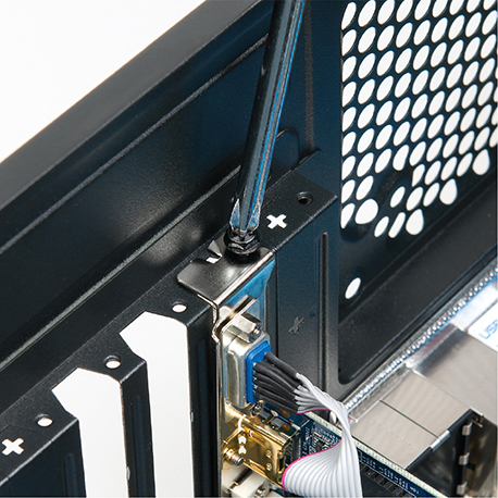
FIGURE 3.5-24 Always screw down all cards.
Step 3: Device Drivers and Other Software
Installing device drivers is fairly straightforward. If you’re upgrading, uninstall the current drivers first. Next, install the correct drivers. If you have a problem, uninstall the new drivers or roll back to a stable one.
Check the manufacturer’s website for the best possible driver. The included drivers may work fine, but there’s often a newer, better driver available on the website. To know if the driver is newer, check the disc. Often the version is printed on the optical media itself; if not, load the disc and poke around. Many driver discs have an Autorun screen or Readme file that advertises the version.
NOTE Microsoft requires signed drivers to provide the most stable platform possible. You simply cannot install unsigned drivers without clunky workarounds. If you upgrade a legacy system to a newer version of Windows, make sure signed drivers exist for its hardware before upgrading.
If you install drivers and your system becomes unstable, roll back to the drivers that worked: open Device Manager, access the properties for the device you want to adjust, and click the Roll Back Driver button on the Driver tab (see Figure 3.5-25).
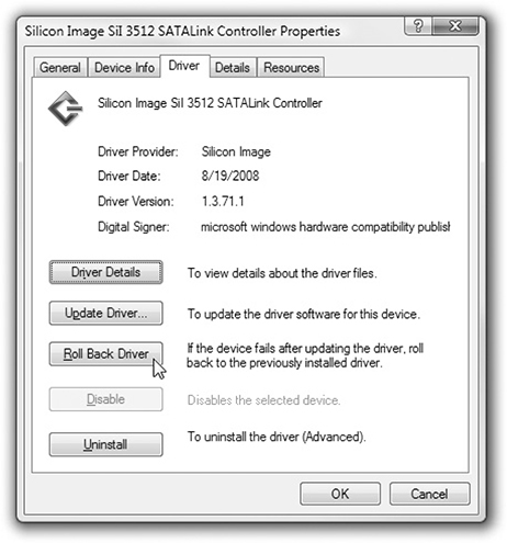
FIGURE 3.5-25 Driver rollback feature
Some devices—notably video cards—have additional support software. These include configuration utilities that live in the Control Panel or notification area. Support software used to be a separate installation from the drivers, but most manufacturers now bundle them in one executable.
Step 4: Verification
Finally, inspect the results of the installation and verify that the device works properly. Immediately after installing, open Device Manager and confirm that Windows sees the device (see Figure 3.5-26). Assuming Device Manager shows the device with no errors, put the device through the paces by making it do whatever it is supposed to do. If you installed a printer, print something; if you installed a scanner, scan something. If it works, you’re done!
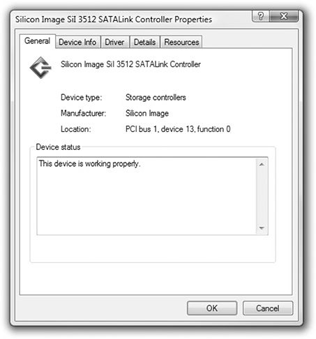
FIGURE 3.5-26 Device Manager shows the device working properly.
REVIEW
Objective 3.5: Given a scenario, install and configure motherboards, CPUs, and add-on cards
• The most common motherboard form factors are ATX, microATX (mATX), and mini-ITX (mITX).
• Motherboards have port clusters at the rear of the motherboard for USB ports, audio jacks, network ports, and other built-in ports.
• PCI slots have been for the most part replaced by PCIe slots, but most motherboards still have one or two PCI slots.
• PCIe is available in versions 1, 2, 3, and 4, with each newer version running about twice as fast as the preceding version.
• PCIe uses lanes, and the most common slot types use from 1 (×1) to 16 (×16) lanes.
• Some motherboards use one or more riser cards.
• Most motherboards have at least one CPU socket.
• Motherboards support either Intel or AMD CPUs. They are not interchangeable.
• Most hard drives and optical drives connect to SATA ports.
• Some older systems in use also have IDE ports.
• Front panel connectors are used for the on/off switch, signal lights, and similar functions.
• Internal USB connectors (headers) on the motherboard can be used to add more USB ports and are available in USB 2.0, USB 3.0, and USB-C versions.
• The system BIOS is the firmware that stores the system BIOS routines for basic system configuration and the CMOS setup utility; it can be updated with a download from the motherboard maker.
• UEFI is the current firmware generation supporting hard drives over 2.2 TB and offering other benefits.
• One of the most important BIOS/UEFI settings is boot order, along with security, SATA drive, and I/O device settings.
• BIOS/UEFI security settings include passwords and drive encryption with TPM, LoJack, or SecureBoot.
• The CMOS battery enables the motherboard to retain BIOS/UEFI settings when disconnected from external power.
• Multicore processors have two or more processor cores.
• Simultaneous multithreading such as Intel Hyper-Threading or AMD SMT enables a processor core to support two execution threads, making it perform faster.
• Processor clock speed is a multiple of the system clock speed.
• Overclocking runs CPUs at faster bus and clock speeds than normal.
• Virtualization is supported by most AMD and Intel CPUs and is enabled through BIOS/UEFI firmware.
• Modern CPUs feature two or more cores, multithreading (Hyper-Threading or SMT) in some models, support for overclocking, and integrated graphics in some models.
• Intel CPUs use LGA sockets, while AMD CPUs use AM, FM, or TR sockets.
• Heat sinks with fans or liquid cooling elements are used to cool down CPUs.
• Thermal material interfacing (thermal paste or tape) is used between cooling devices and CPUs.
• Video cards use faster RAM than motherboards and most have cooling fans.
• Most video cards require extra power from a PCIe power connector.
• Sound cards and onboard sound chips support stereo or surround audio.
• SPDIF, HDMI, and DisplayPort output digital audio.
• NICs have status lights to indicate connection and speed.
• USB expansion cards and header cables enable you to add more USB ports.
• eSATA cards and eSATA-SATA conversion brackets enable you to add more eSATA ports.
• The process of installing expansion cards includes checking for compatibility (knowledge), proper physical installation (avoiding ESD and securing the card), installing device drivers, and verifying proper card operation.
3.5 QUESTIONS
1. You have been tasked to review motherboard form factors for a project. The number one requirement is that the motherboard be as small as possible. Which of these motherboards is the smallest?
A. microATX
B. Mini-ITX
C. ITX
D. ATX
2. Your client has selected PCIe version 3.0 graphics cards to refresh the organization’s video editing workstations. However, the systems support PCIe version 2.0. Which of the following is true?
A. The cards will run at PCIe 3.0 speeds.
B. The motherboards must be replaced with PCIe 3.0–compatible versions.
C. The cards cannot be used.
D. The cards will run at PCIe 2.0 speeds.
3. You are upgrading your personal system with USB 3.0 (USB 3.1 Gen 1) devices but have run out of external ports. You need two more ports. Which of the following would provide these ports?
A. USB 2.0 header cable
B. USB-C header cable
C. USB 3.0 header cable
D. SATA-to-USB conversion cable
4. You are creating documentation for other technicians to use as they configure the UEFI firmware on new systems. Which of the following should not be in the documentation because it is incorrect?
A. SATA drives cannot be configured as hot-swappable.
B. USB ports can be disabled.
C. The boot sequence can be changed.
D. You can exit UEFI/BIOS setup without saving changes.
5. Your client wants you to install an LGA 1155 processor into a motherboard that uses an FM2 processor. Which of the following statements about these parts is correct?
A. Intel parts work in AMD motherboards.
B. The LGA 1155 will not fit into this motherboard.
C. The FM2 processor is an older Intel processor.
D. The FM2 processor has 2000 pins.
3.5 ANSWERS
1. B The Mini-ITX (mITX) is the smallest motherboard listed.
2. D When two different PCIe versions are present (slot and card), the slower version is used.
3. C A USB 3.0 header cable provides two USB 3.0 ports; however, not all motherboards with USB 3.0 have headers.
4. A SATA drives are hot-swappable when configured as AHCI in the UEFI/BIOS firmware.
5. B LGA 1155 is an Intel CPU socket, but FM2 is an AMD CPU socket; they are not compatible.
Objective 3.6 Explain the purposes and uses of various peripheral types
Many peripherals can be connected to a computer’s external video, audio, and USB ports. This section presents the long list of peripherals under objective 3.6 by grouping them into three logical categories: output devices, input devices, and drives and storage devices.
EXAM TIP Be sure to know the purpose of each device in this objective.
Output Devices
The following devices produce output on paper, as files, or as sound.
Printer
Printers produce output on paper, envelopes, card stock, labels, or transparency media. Printers are often combined with scanners, copiers, or fax devices in both offices and homes. Most printers used in home or office environments use laser or inkjet technologies, but thermal and impact printers are also used in some specialized environments.
Cross-Reference
Monitors
Monitors, also called displays, are connected to video cards or ports so users can view what is happening in the operating system and with running apps. Monitors formerly used CRT technology, and later LCD with fluorescent backlights, but are now based on LCD with LED backlights or organic LED (OLED) technologies. Most computers can be connected to two or more monitors.
VR Headset
A VR (virtual reality) headset creates an immersive experience by mounting two high-resolution screens into a headset that blocks external visual sensory input. VR headsets are used in 3-D gaming and other 3-D uses that enable the user to interact with a software-created 3-D world.
Projector
A projector connects to the same video ports used by monitors, enabling a room to see a computer presentation, documents, photos, or movies. Projectors typically use one of two display technologies—LCD or DLP—and have zoom lenses to enable the projector to work in a variety of room sizes.
Lumens/Brightness
When selecting a projector, one consideration is the brightness of the output, measured in lumens (the higher the lumen rating, the brighter the projected image).
Speakers
Speakers enable computers, tablets, and smartphones to double as high-quality music playback stations. Speakers can be connected via 3.5-mm analog jacks, SPDIF jacks, or Bluetooth wireless connections. Speakers built into HDTVs can be driven by HDMI or DisplayPort connections. When a different audio output is added, the sound mixer app settings need to be changed to use the new audio output.
Headset
Headsets can be used in place of speakers for privacy and many also include microphones. Like speakers, they can be connected to 3.5-mm analog jacks or work wirelessly with Bluetooth. Some connect to USB ports.
Input Devices
The following devices are used to input commands, text, or other types of data into a program, storage, or computer RAM.
Mouse
Pointing devices enable us to instruct the computer to perform an action at some spot on the screen. Most computers have a mouse attached (same connection options as keyboards) with two buttons and a scroll wheel. Modern optical mice use light-emitting diodes (LEDs) or lasers to track and translate movement to the screen.
Keyboard
The keyboard has been the primary computer input device since the original IBM PC several decades ago. Keyboards use wired (USB, PS/2) or wireless (Bluetooth, radio frequency [RF]) interfaces. Each OS comes with support for standard QWERTY keyboards, but extra features like multimedia controls or color-changing keys require drivers. You can adjust settings such as how fast keys repeat in the Keyboard Control Panel applet (Windows) or System Preferences (macOS). Linux supports these options, but the menu name and location differ among distros.
NOTE The eternal struggle with keyboards is keeping them clean; educate users who need a replacement not to eat or drink over it!
Touchpad
A touchpad uses finger movements to scroll, control the cursor, and issue other commands. Touchpads typically are included only on portable computers, but standalone USB or Bluetooth touchpads are available for desktop computers.
Signature Pad
Signature pads are devices that incorporate digitizer technology to convert users’ signatures to digital. They are commonly used in banks, credit unions, or other point-of-sale locations where a signature must be captured. They are replacing paper signature slips.
Game Controllers
You can control most modern computer games with a mouse and keyboard, but some also support joysticks, gamepads, and steering wheels. Modern controllers connect via USB, and you’ll need to install drivers for complex ones. Joysticks (see Figure 3.6-1) mimic the iconic aircraft control stick; gamepads (see Figure 3.6-2) resemble gaming console controllers; steering wheels may come with pedals and shifters. After connecting these devices, you might need to calibrate them before they can be used.
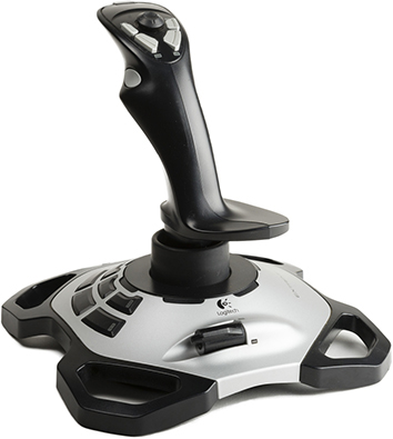
FIGURE 3.6-1 A joystick
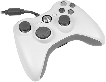
FIGURE 3.6-2 A gamepad
ADF/Flatbed Scanner
A flatbed scanner is used to create digital versions of documents or photos. An auto document feeder (ADF) is built into many scanners to make scanning or copying of multiple documents faster.
NOTE A multifunction device (MFD) combines printer, scanner, and copier functionality and is considered an input/output device.
Barcode Scanner/QR Scanner
Barcode scanners and QR scanners use lasers to read standard Universal Product Code (UPC) barcodes or Quick Response (QR) codes and are typically used with point-of-sale (POS) or warehousing systems to identify items.
Camera/Webcam
A dedicated digital camera (see Figure 3.6-3) can offer higher quality, features tuned to the task at hand, and more room for creativity than the camera built into a smartphone.

FIGURE 3.6-3 Typical dedicated digital camera
Digital cameras typically store data on flash memory cards or internal hard drives, but may also have Wi-Fi for quick sharing. Windows and macOS both have programs for basic photo and video organization, editing, and sharing, though professional image- and video-editing software can unlock your creativity (for a price).
Unlike regular cameras, where higher quality is better, webcams (cameras in or mounted on computer monitors) tend to have modest, bandwidth-friendly resolutions. They often include a microphone, but you can also use a standalone mic or headset.
Windows’ own webcam drivers are limited, so always install drivers supplied with a camera before you plug it in.
Microphone
The computer is a great platform for recording and editing sound and music. The most common option is plugging a microphone into a microphone jack or a USB port to record your voice, make phone and video calls, coordinate with teammates in online games, and control a computer with voice commands. Musicians, however, need special hardware.
KVM
A keyboard, video, mouse (KVM) switch is a hardware device that enables a single mouse, keyboard, and monitor to control multiple computers (though some KVMs reverse that capability, enabling a single computer to be controlled by multiple input devices). KVMs are useful in data centers with many rack-mounted servers and limited space. Once you connect a keyboard, mouse, and monitor to the KVM and connect the KVM to the desired computers, you can use keyboard hotkeys (such as pressing the SCROLL LOCK key twice) to toggle between computers connected to the KVM.
Magnetic Reader/Chip Reader
Magnetic reader/chip reader attachments for smartphones and tablets enable them to be used to read credit and debit cards to accept payments via the cellular network. Magnetic reader/chip reader devices are also incorporated into point-of-sale (POS) computers for use in retail stores.
NFC/Tap Pay Device
NFC/tap pay devices use Near Field Communication to enable payments from smartphones to payment services at gas stations and retail stores.
Smart Card Reader
Many enterprise-level businesses use a smart-card system that requires employees to display proper credentials to obtain the correct level of access to company resources. A smart card reader comes in many forms, from a small device attached to a laptop computer to a panel next to a secure door, and scans chip-embedded ID badges or other devices.
Drives and Storage Devices
The following peripheral devices are used to load apps, store data, or record data.
Optical Drive Types
CD, DVD, and Blu-ray Disc (BD) drives are used to load apps, to view archival data stored on optical discs, or, when using recordable or rewriteable drives and media, to create copies of files or operating system images. Although these drives are sometimes installed into internal drive bays, most late-model laptops and some desktops use external versions instead.
External Storage Drives
External storage drives can be used to transfer data between systems, as additional primary storage, or for data backups. The most common connection methods are USB 2.0/3.0 (for low-end flash drives and CD/DVD optical drives), USB 3.0/3.1/Type-C (for high-capacity flash drives, hard disks, SSDs, or Blu-ray Disc drives), or Thunderbolt (for hard disks or SSDs). Some external drives connect to the eSATA ports found on some older systems.
EXAM TIP Make sure you know which connection types are used by external storage drives.
REVIEW
Objective 3.6: Explain the purposes and uses of various peripheral types
• Output devices include printers, speakers, headsets, VR headsets, and projectors.
• Input devices include ADF/flatbed scanners, barcode/QR scanners, mice, KVM switches, keyboards, touchpads, signature pads, game controllers, camera/webcams, microphones, magnetic reader/chip readers, NFC/tap pay devices, and smart card readers.
• Storage devices include optical drives and external storage drives.
3.6 QUESTIONS
1. Your client cannot use a mouse and does not want to use a laptop, so your job is to choose an alternative input device. Which of the following can be used in place of a mouse?
A. Touchpad
B. Signature pad
C. Keyboard
D. Joystick
2. To enable video conferencing in privacy, your company should install which of the following components on its desktop computers?
A. Speakers and camcorders
B. Headsets and projectors
C. Headsets and webcams
D. Speakers and digital cameras
3. A client calls, complaining of no sound from his computer after replacing separate audio speakers and a VGA monitor with an HDMI display with built-in speakers. Which of the following needs to be done to hear sound again?
A. New display is defective—return it to vendor for replacement
B. Disable on-board sound
C. Enable speakers in display with pushbutton
D. Change sound mixer output to HDMI
4. Your client, a restaurant owner, wants to add support for Apple Pay to its POS systems. Which of the following types of devices is needed?
A. Signature pad
B. NFC/tap pay device
C. Magnetic reader/chip reader
D. Smart card reader
5. You are building a personal gaming system. Which of the following will not be a feature to add for this purpose?
A. Signature pad
B. VR headset
C. Game controller
D. Joystick
3.6 ANSWERS
1. A A touchpad, whether built into a laptop keyboard or plugged into a USB port, is a very satisfactory mouse replacement for many users.
2. C Headsets will help keep conference content confidential, while a webcam will enable attendees to see each other for better communication.
3. D The computer will continue to route sound to the original audio jack until the new source is selected in the mixer app.
4. B NFC/tap pay devices are used by device-based payment systems like Apple Pay.
5. A A signature pad is useful on a POS or banking device, but has no purpose on a gaming PC.
Objective 3.7 Summarize power supply types and features
Power supplies enable computers to run, and are an often-neglected cause of failures and crashes. As port-powered peripherals become more numerous and CPUs and GPUs require more power, power supplies with larger wattage ratings are becoming more important.
Input: 115 V vs. 220 V
A desktop computer includes a power supply unit (PSU) (see Figure 3.7-1) that converts high-voltage AC power to low-voltage DC power for the computer’s motherboard and devices. Its internal fan also helps cool the components and drives. When connected to a properly grounded outlet, the power supply also provides grounding for all the other equipment inside the case.

FIGURE 3.7-1 Power supply
In the United States, standard AC comes in somewhere between 110 and 120 V, often written as ~115 VAC (but 115V in objective 3.7). Most of the rest of the world uses 220–240 VAC (220V in objective 3.7), so many power supplies offer a little dual-voltage switch on the back that enables you to use them anywhere. Power supplies with voltage-selection switches are referred to as fixed-input. Power supplies that you do not have to manually switch for different voltages are known as auto-switching.
CAUTION If you are using a fixed-input power supply connected to a 220–240 VAC power line, don’t turn it on if the voltage selector switch is set to 115 VAC. That’s a sure way to kill the power supply and possibly other components as well!
EXAM TIP The power connector for the AC plug on the back of a power supply is called an IEC-320 connector. CompTIA A+ 1001 exam questions might refer to the power supply as a PSU.
Power supplies come in various form factors that determine the physical size, shape, and connectors.
ADDITIONAL RESOURCES To learn more about power supply form factors, see www.tomshardware.com and search for “A Basic Guide To Motherboard, Case and Power Supply Form Factors.”
Power supplies also vary in output, efficiency, the number of 12-V rails used, and how much power each rail can supply. While a single-rail power supply is usually enough for an average computer, high-end systems may need a multi-rail power supply. In practice, avoid running too many devices off one rail in a multi-rail power supply.
EXAM TIP Make sure you know the voltage ranges (~115 VAC versus ~230 VAC) supported by power supplies.
Output: 5 V vs. 12 V
The PSU converts the high-voltage AC to low-voltage DC to power motors on devices such as hard drives and optical drives (12-V current) and onboard electronics (5-V current). The device connectors you’re most likely to see are serial ATA (SATA), Molex, and mini (also called Berg) (see Figure 3.7-2). Better power supplies have a dedicated 6- or 8-wire PCIe connector for PCI Express video cards (see Figure 3.7-3).

FIGURE 3.7-2 Mini, Molex, and SATA power connectors (left to right)
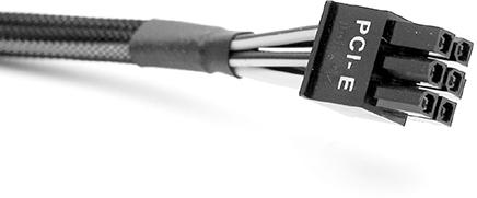
FIGURE 3.7-3 PCIe power connector
Power supplies connect to the motherboard with these connectors: the 20- or 24-pin (wire) P1 connector, the primary power circuit; and a 4-wire P4 secondary power connector or 8-wire EPS12V power connector, which typically supplies power to the CPU (see Figure 3.7-4). The power supply converts AC to DC current, so all power leads from the power supply carry DC current.
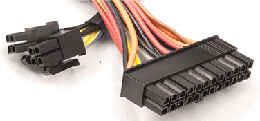
FIGURE 3.7-4 EPS12V/ATX12V connectors (left) and P1 connector (right). These use one 4-pin (P4) connector on motherboards that use a 4-pin ATX12V connector, and both on motherboards that use an 8-pin EPS12V connector.
EXAM TIP The 5-volt orange (sometimes gray) wire on the P1 connector is called power good and is used in the initial boot sequence.
Many modern ATX motherboards use an 8-pin CPU power connector, variously referred to as EPS12V, EATX12V, and ATX12V 2×4. Half of this connector will be pin-compatible with the P4 power connector; the other half may be under a protective cap.
Check the motherboard installation manual for recommendations on when to use the full 8 pins. For backward compatibility, some power supplies provide an 8-pin power connector that can split into two 4-pin sets, one of which is the P4 connector (refer to Figure 3.7-4). Although they look similar, the 8-pin CPU power connector is not compatible with the 8-pin PCIe power connector. Table 3.7-1 lists the common connectors of the ATX12V power supplies—the current standard—with their voltages and uses.
TABLE 3.7-1 Power Connectors and Voltages

CAUTION Power connectors are keyed so that you can’t easily plug them in backward, but some older designs can be forced. Reversing the power on a device will fry it. Don’t force a power connector.
24-pin Motherboard Adapter
To enable the same power supply model to work with older 20-pin ATX motherboards and modern motherboards that use 24-pin connectors, some vendors provide 24-pin motherboard adapters.
Wattage Rating
Power supplies provide a certain wattage that the motherboard, drives, and fans draw on to run. That’s the desired output. Power supplies also produce harmonics, the hum you hear when the power supply runs, that can cause problems with the power supply and other electrical devices on the circuit if not controlled.
EXAM TIP Wattage is the amount of amperage flowing at a specific voltage, usually written as W = VA.
A computer requires sufficient wattage to run properly. Every device in the system also requires a certain wattage to function. For example, a typical magnetic hard drive draws 15 W of power when accessed (SSDs use less), whereas a quad-core Intel i9-9900K CPU draws a whopping 162 W at peak usage—with average usage around 92 W. The total combined wattage needs of all devices is the minimum you need the power supply to provide.
If the power supply can’t produce the wattage needed by a system, that computer won’t work properly. Because most devices in the system require maximum wattage when starting, the typical outcome of insufficient wattage is a paperweight that looks like a computer. The only fixes for this situation are to remove the device or get a power supply with more wattage. Today’s systems require at least 500+ watt power supplies to function.
Good computer power supplies come with active power factor correction (active PFC), extra circuitry that smoothes out high-voltage AC power before passing it to the main power supply circuits to eliminate harmonics. Avoid any older and poorer power supplies without this circuitry.
Most active PFC power supplies are auto-switching, meaning they can detect the voltage coming from the wall and adjust accordingly. You can use an auto-switching power supply anywhere in the world, from the ~115 VAC in New York City to the ~230 in Hong Kong. This is especially important with portable computers!
Number of Devices/Types of Devices to Be Powered
Before purchasing a new power supply, it is essential to determine the number of devices and types of devices it will power. Power supplies vary greatly in the number of Molex, SATA, and mini (Berg) connectors, and some only support only a single PCIe power connector. Molex connectors are no longer used for drives, but are frequently used to power case fans if there are not enough fan ports on the motherboard and can also be adapted to run SATA drives or devices that use mini connectors.
Try to avoid the use of splitters to run more devices than can be connected directly to a power supply. Cheap splitters that use thin wires can overheat, and even the best-quality splitters introduce additional points of potential failure into a system.
Power Supply Installation Notes
Be careful when you work with power supplies or inside a computer. Here’s why: an ATX power supply never turns off. As long as it is connected to AC power, the power supply will feed 5 V DC to the motherboard. Installing cards, chips, or memory modules to a motherboard while power is flowing could damage those components. Remember, always unplug the power supply and wait about ten seconds before you work inside the computer or disconnect the power supply for replacement!
Before you connect the power supply, you’ll need to mount it inside the case with four standard case screws (see Figure 3.7-5). The only exceptions are some small or proprietary cases.

FIGURE 3.7-5 Power supply secured in case
REVIEW
Objective 3.7: Summarize power supply types and features
• Power supplies support ~115 VAC and ~230 VAC inputs, either through a sliding switch or with internal auto-switching.
• The IEC-320 connector is used for the AC plug on the rear of the power supply.
• Power supplies generally provide 5-V or 12-V power to peripherals via the SATA, Molex, and mini (Berg) power leads. PCIe power leads provide 12-V power to PCIe cards.
• P1 provides power to the motherboard using a 24-pin (newer) or 20-pin (older) keyed connector.
• Older motherboards use the P4 4-pin 12-V connector to provide power to the CPU (the power is stepped down by the motherboard); newer motherboards use the EPS12V 8-pin connector for this job.
• Higher wattage ratings in power supplies are needed when the power draw of installed and onboard devices approaches or exceeds the output of the current power supply.
• Active PFC helps eliminate harmonics for better-quality power.
• Splitters can be used to power additional devices, but it’s better to use a power supply that has enough leads of the right types for your devices.
• Power supplies are typically mounted using four screws on the rear that fasten through the case wall.
3.7 QUESTIONS
1. Your client’s 20-pin ATX power supply has failed. Which of the following can be used to enable a modern power supply to be used as a replacement?
A. ATX12V adapter
B. 24-pin motherboard adapter
C. EPS12V adapter
D. Aux adapter
2. Your company is taking several desktop computers to a European country for a long-term project. The power supplies are auto-switching, but a component with a design that varies by location is also needed. That component uses the IEC-320 connector on the power supply. Which of these is it?
A. AUX adapter
B. 115-230VC AC converter
C. Power cord
D. EPS12V adapter
3. You are providing telephone support to a new technician who is using a multimeter to check a power supply. Which of the following voltage/color combinations is incorrect?
A. 12-V DC is yellow
B. Black is 3.3-V DC
C. Orange is 3.3-V DC
D. 5-V DC is red
4. You have received a frantic call at home from a fellow gamer who has swapped her old PCIe video card for a new one and can’t plug the original PCIe power cable into the new card. Which of the following is the best solution?
A. Look for an 8-pin PCIe lead
B. Use the 8-pin EPSV12 lead
C. Cut off some power supply cables and splice in a new header
D. Put the old card back in because the new one can’t be used
5. You are checking out the fans built into a system that is overheating. After verifying that the system is not overclocked, you notice that there are two case fans that can’t be plugged into the motherboard. Which of the following power lead types is the best candidates for use with these fans?
A. Mini
B. ATX12
C. PCIe
D. Molex
3.7 ANSWERS
1. B 24-pin motherboard adapter enables a modern 24-pin power supply to work with an older system and get the benefits of potentially higher wattage.
2. C The power cord varies from country to country, and IEC-320 is the designation for the power supply cable connector.
3. B Black is ground, not 3.3-V DC.
4. A Many (but not all) power supplies have both 6-pin and 8-pin PCIe power leads.
5. D Molex connectors are compatible with most case fans as well as with IDE hard drives and optical drives.
Objective 3.8 Given a scenario, select and configure appropriate components for a custom PC configuration to meet customer specifications or needs
Now it’s time to bring all of this component knowledge together and look at seven types of custom PCs and their typical components and configurations.
EXAM TIP Make sure you can identify the requirements for each custom PC configuration.
Standard Thick Client These systems meet the recommended requirements for running Windows (or selected OS) and standard desktop applications, such as office productivity and networking applications. Network connections are not specifically mentioned, but they are needed for operating system compatibility and updates.
Thin Client Thin clients are low-power computers with network connectivity that run or access an OS and applications housed on a server, leveraging the server’s power. A thin client runs basic applications—to do e-mail and access the Web—and meets minimum OS requirements.
Virtualization Workstation A virtualization workstation is essentially the opposite of a classic thin client as it runs multiple operating systems at once through virtual machines. Correspondingly, it needs maximum RAM and a multicore CPU.
Audio/Video Editing Workstation These media workstations require specialized audio and video cards; a large, fast hard drive; and multiple (dual) monitors.
Graphic/CAD/CAM Design Workstation This mouthful refers to a computer built around specialized computer-aided design (CAD) software, such as AutoCAD, for designing and modeling physical objects. Such a machine needs a fast SSD, high-end video card, and maximum RAM.
Gaming PC A gaming PC has similar needs to a graphics workstation, though the video card should use a high-end/specialized game-oriented GPU rather than a workstation GPU. It also needs a high-definition sound card, high-end cooling, and SSDs for storage
Network Attached Storage Device A network attached storage (NAS) device has several roles, such as central file storage, print server, and streaming media machine. CompTIA specifically lists the following requirements:
• Media streaming
• File sharing
• Gigabit network interface card (NIC)
• Hard drive or RAID array using hard drives
REVIEW
Objective 3.8: Given a scenario, select and configure appropriate components for a custom PC configuration to meet customer specifications or needs
• Standard thick clients meet the recommended requirements for running the selected OS and desktop applications.
• Thin clients require network connectivity and meet the minimum requirements for running the selected OS and basic applications.
• Virtualization workstations have maximum RAM and CPU cores.
• Audio/video editing workstations require specialized audio and video cards, dual monitors, and a large, fast hard drive.
• Graphic/CAD/CAM design workstations are similar to AV editing workstations but use graphics workstation cards and SSD.
• A gaming PC is similar to a graphics workstation but uses a gaming GPU, high-end cooling, and SSDs for fastest storage.
• A network attached storage device is optimized for sharing files and streaming media by using a RAID array, Gigabit NIC, and hard drive.
3.8 QUESTIONS
1. Your client needs to switch the role of an existing computer to be used as an A/V editing workstation. Which of the following is the least suitable candidate for upgrading?
A. Thick client
B. Gaming PC
C. Thin client
D. Virtualization workstation
2. You are examining a computer that was salvaged from a fire to determine its previous use. It contains a Gigabit Ethernet NIC and a RAID array built with four 4-TB hard disk drives. It uses onboard video and sound. What was this computer most likely used for?
A. Thick client
B. Virtualization workstation
C. A/V editing workstation
D. Network attached storage device
3. Your client has a gaming PC that is almost perfect for being used as a graphic/CAD/CAM design workstation. However, one component should be exchanged for a workstation-grade component. Which of these is it?
A. Graphics card
B. RAM
C. Hard disk
D. Keyboard
4. Your client wants to use existing computers as thin clients, so you are going through the client’s excess computer inventory looking for suitable candidates. Which of the following would be the most suitable thin client for use with Windows 10 64-bit edition?
A. Computer with 8 GB of RAM and a 4-TB hard disk
B. Computer with Intel ATOM and 1 GB of RAM
C. Computer with Intel Celeron and 2 GB of RAM
D. Computer with Core i7 and a 2-TB hard disk
5. You are testing a liquid cooling system in one of your personal systems. Which of the following configurations are you most likely developing?
A. Virtualization workstation
B. Gaming PC
C. Audio/video editing workstation
D. Network attached storage device
3.8 ANSWERS
1. C Thin clients have low-power CPUs, minimum RAM, and sometimes lack PCIe slots suitable for video cards, so they’re the least likely candidates.
2. D These are the major features of a network attached storage device. The use of onboard video and sound indicate these features are relatively unimportant to the primary task.
3. A Workstation graphics cards are optimized for 2-D/3-D CAD, while consumer graphics cards are optimized for 3-D gaming.
4. C This computer has the smallest amount of RAM supported for use with 64-bit Windows, as well as a processor that meets minimum requirements.
5. B Gaming PCs are typically overclocked, and liquid cooling is more effective for cooling than most air coolers.
Objective 3.9 Given a scenario, install and configure common devices
As part of your work, you will frequently need to install and configure common computing devices. Understanding these processes is also part of the CompTIA A+ 220-1001 exam, as you will learn in the following sections.
Desktop
Desktop computers can be divided into two classes:
• A thin client is a low-power computer with network connectivity that runs or accesses an OS and applications housed on a server, leveraging the server’s power. A thin client runs basic applications—to do e-mail and access the Web—and meets minimum OS requirements.
• A thick client meets the recommended requirements for running Windows (or selected OS) and standard desktop applications, such as office productivity and networking applications.
Thin Client, Thick Client
Assuming the client computer has already been built and had an operating system installed, the installation and configuration steps for either type of client include
1. Connect AC power to the power supply.
2. For a wired client, connect network cable to the NIC.
3. Connect display, keyboard, mouse, and other peripherals.
4. Turn on the system.
5. Connect to the OS image on the network if the OS is not installed locally.
6. For a wireless connection, connect to the appropriate SSID.
7. Configure the display and other peripherals.
For additional steps, see “Account Setup/Settings.”
Cross-Reference
Account Setup/Settings
With either type of client, you must
• Set up one or more user accounts.
Cross-Reference
• Set up applications.
Cross-Reference
• Configure the desktop and Start menu according to company guidelines.
Cross-Reference
EXAM TIP Make sure you know the steps required to configure desktop thick/thin clients.
Laptop/Common Mobile Devices
Laptops and common mobile devices may require additional configuration beyond what’s necessary with a thin client or thick client.
EXAM TIP Make sure you know the steps required to configure laptop and common mobile devices.
Touchpad Configuration
Use the Settings | Devices | Mouse dialog or the Mouse applet in Control Panel for touchpad configuration. You can change sensitivity and much more in either tool, such as
• Setup for right-hand or left-hand use
• Scroll settings
• Gesture settings
• Settings to avoid phantom touches
Touchscreen Configuration
Depending on the device, the following might need to be checked or configured:
• Multi-touch settings
• Gestures
• Scroll settings
• Calibration
In Windows, open Control Panel | Hardware and Sound | Calibrate | Touch Input to configure these options. In Linux, install the multi-touch framework recommended for your distro (Ubuntu uses uTouch) and any additional apps needed (varies by distro and framework).
Application Installations/Configurations
Applications may need to be installed and configured with options such as
• Paid or free (reduced-feature) version installation
• Installing a standard software image using a Mobile Device Management (MDM) app
• Network and browser settings
Cross-Reference
Synchronization Settings
Keeping local and network files synchronized is critical to trouble-free mobile device function. Settings might include
• Setting up cloud storage and file transfer
• Specifying online/offline file access
• Installing custom file sync apps
• Configuring file sync apps and settings
Cross-Reference
Account Setup/Settings
As with thin and thick clients, you must do the following for laptops and common mobile devices:
• Set up one or more user accounts.
• Set up applications.
• Configure the icon layout or desktop and Start menu according to company guidelines.
Wireless Settings
Wireless settings might include
• Default SSIDs
• VPN installation and configuration
• Firewall setup
Cross-Reference
REVIEW
Objective 3.9: Given a scenario, install and configure common devices
• Thin and thick clients differ in amounts of RAM, hard drive size, and processor performance.
• Both require account setup, application set up, and desktop and start menu configuration.
• Laptop and mobile devices also require touchpad configuration, touchscreen configuration (when equipped), synchronization settings, and wireless settings.
3.9 QUESTIONS
1. Which of the following device types require(s) account and application setup?
A. Thick client
B. Laptops and mobile devices
C. Thin client
D. All of the above
2. Setting up cloud storage and file transfer is an aspect of which type of setting?
A. Account setup
B. Synchronization
C. Wireless
D. Touchscreen
3. Your client formerly used a desktop computer and is having problems with phantom touches moving the cursor on his laptop. Which configuration category needs to be performed?
A. Touchscreen configuration
B. Keyboard configuration
C. Touchpad configuration
D. Synchronization settings
4. You are creating a checklist for setting up laptop and mobile devices. Which of the following doesn’t belong in the wireless settings category?
A. Gigabit Ethernet NIC speed/duplex
B. Default SSID
C. VPN installation and configuration
D. Firewall setup
5. Which of the following is a fast way to configure and install applications on standard and mobile devices?
A. Custom file sync apps
B. Standard software image
C. Firewall
D. Desktop configuration per company standards
3.9 ANSWERS
1. D All of these device types require these settings.
2. B Synchronization includes cloud storage and file transfer as well as file sync apps.
3. C Touchpads can be configured to ignore phantom touches from fingers or thumbs to avoid moving the mouse pointer accidentally.
4. A A Gigabit Ethernet NIC is used in wired networking, not wireless networking.
5. B A standard software image contains the software and settings used by an organization, so installing it rather than making individual changes is much faster.
Objective 3.10 Given a scenario, configure SOHO multifunction devices/printers and settings
One of the most common processes you will perform in a small office/home office (SOHO) environment is the setup and configuration of multifunction devices (MFDs) and printers. This objective guides you through the essential steps required to configure these devices. When “printer” is stated in the following sections, the instructions also apply to MFDs.
EXAM TIP Make sure you know the steps required to install printers and their drivers.
Use Appropriate Drivers for a Given Operating System
Most printers are plug-and-play devices on Windows; just plug in the printer and let Windows automatically detect and install the driver. If the system does not detect the printer, open the Devices and Printers (Windows 7 and up) applet and click Add a Printer to open the Add Printer Wizard, which enables you to install a local printer or a network printer. This distinction isn’t perfect; you can use the local printer option to add network printers manually—it just doesn’t automatically search for them. In Windows 10, you can also use Settings | Devices | Printers & scanners and click Add a printer or scanner.
macOS connects automatically with AirPrint-compatible printers or, in most cases, installs drivers for you. If you don’t have an AirPrint-compatible printer, and you are connecting via USB, make sure you have updated your macOS installation so you have the latest printer drivers, then turn the printer on. Install updated drivers if prompted. To install a Wi-Fi printer that is not AirPrint-compatible, you might need to connect your printer via USB temporarily to configure it.
Linux printer installation varies with the drivers available. Many HP and Brother printers can use manufacturer-provided Linux drivers. To install other printers with typical Linux GUIs, use the Printers or System | Printers option in your desktop environment to select a printer and use the drivers provided with the GUI. The Common Unix Printer Service (CUPS) is used if printer configuration software is not provided; install it using your Linux distribution’s package manager.
Installing a Local Printer
Unless your printer is very new, or very old, you’ll probably never use this option except, surprisingly, to install standalone network printers by IP address or hostname. Even here, Windows will detect most modern printers on its own, so you’ll just use this if it refuses to detect yours.
In Windows 7, click Add a local printer. In the Create a new port drop-down box, select Standard TCP/IP Port. Click Next. Type the IP address here. Windows 8/8.1/10 is even simpler: if Windows doesn’t automatically detect your new printer, click The printer that I want isn’t listed and select Add a printer using TCP/IP address or hostname.
You’ll need to manually select the proper driver (see Figure 3.10-1). Windows includes a lot of printer drivers, but you can use the Have Disk option to install from the printer’s driver disc (Windows will require administrator privileges to proceed). The Windows Update button enables you to grab the latest printer drivers via the Internet.
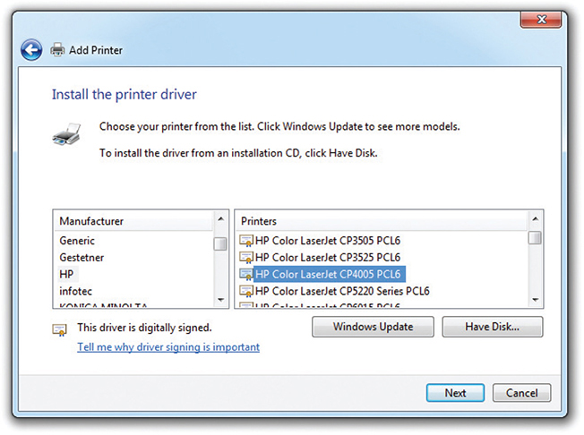
FIGURE 3.10-1 Selecting a printer driver for a manual printer installation
Installing a Network Printer
When you try to install a network printer, the Add Printer Wizard will scan for available printers and usually find the one you want. Just select it, click Next, and follow the procedure just discussed to install drivers and set up the printer. You’ll need to configure it manually if Windows can’t find it, and the options vary if you are connected to a domain or workgroup (in homegroups, all connected printers are shared automatically if printer sharing is enabled).
In a workgroup, you can browse the network, connect to a printer by name or URL, or use a TCP/IP address or hostname. On a domain, you can search and browse by parameters such as printer features, location, and so on. Once you select a printer, you may be prompted to provide drivers using the method described earlier.
EXAM TIP Windows 7 and newer (excluding Home/Basic editions) also include the Print Management console in Administrative Tools. It enables you to view and manage printers, drivers, and Windows print servers on your system or network. Print Management’s advanced features go beyond the CompTIA A+ exams, but know it centralizes (and sometimes enhances) standard Windows printer controls.
Configuration Settings
Once the printer is installed in Windows, find it in the Devices and Printers applet, right-click it, and select Printing preferences to configure how your printer will print documents. To configure a printer in macOS, open the Print dialog, select your printer, click Show Details, and choose the options needed. To configure a printer in Linux, see the documentation for your GUI or distribution.
Options vary by device and features, but here are the ones you need to know for this objective.
EXAM TIP Make sure you know the essential configuration settings covered in this section.
Duplex The duplex setting specifies whether and how to use each side of a printed page. Simple duplexing uses the front and back of each sheet in sequence, but advanced options reorient the print to account for binding on any given edge or reorder pages to support folded booklet layouts.
Collate Enabling the collate option prints a full copy of a multipage document before starting the next copy. When disabled, the printer prints all copies of a page before moving to the next page.
Orientation The orientation setting specifies whether to print in landscape or portrait mode.
Quality Quality settings enable you to manage the tradeoffs between quality and speed, ink use, and memory use:
• The most obvious of these, resolution, specifies what DPI the document should be printed at.
• Some printers may let you choose some mode or quality presets that optimize printing for graphics or text, or choose to manually configure your own advanced settings.
• Some printers may have settings that reduce ink or toner used, for economic and environmental reasons.
NOTE The names and descriptions of settings that influence quality might discuss quality itself, ink or toner use, environmental friendliness, or even cost savings. As a result, quality-reducing settings may be scattered around multiple menus.
Device Sharing
Unless multiple users in an office print documents frequently, there’s no need to have a printer for every computer. There are a variety of ways to share printers, as you will see in the following sections.
Wired
The ports built into typical printers for direct connect to a single device also make sharing possible:
• Use a USB switch to share a printer between two nearby computers without the need for networking; if the computer is on a network, you can share the printer as long as the host computer is running (don’t forget to install file and print sharing services!).
• Very old printers use serial switchboxes to share printers (most of these are in museums or have been recycled, but you might run into it on the exam!).
• Use the Ethernet port to plug the printer into a wired network. It will have its own IP address.
Wireless
Many printers today are ready to connect wirelessly to other computers or networks.
• A printer with Bluetooth is ready to connect to any computer or mobile device with Bluetooth after pairing (just make sure you have a suitable printing app for the mobile device).
• A printer with Wi-Fi onboard (802.11 a, b, g, n, or ac) is ready to join your wireless network, have its own IP address, and be ready to receive print jobs after configuration. The hardest part of the process may be entering the SSID and encryption key using the printer’s control panel.
Infrastructure vs. Ad Hoc
Infrastructure is a long name for the way that normal Wi-Fi networks work: every device, including the printer, uses an SSID to connect to an AP or router.
Ad hoc, on the other hand, allows for direct connection between any two Wi-Fi devices without going through a router or AP. Windows 8 and later do not officially support ad hoc connections, but you can find a variety of methods online for setting up an ad hoc connection to your printer.
Integrated Print Server (Hardware)
You can purchase a standalone print server device to network one or more traditional wired printers—but you may not be able to use all features of an MFD connected this way. First, see if your router has an integrated print server, in which case you can plug your printer into the router’s USB port.
Cloud Printing/Remote Printing
A variety of applications such as Google Cloud Print blur the line between traditional and virtual printing. These apps install a virtual printer on your system that wraps up your document and sends it out over the Internet or other network to a cloud server, which eventually routes it to a real printer for printing—all without your system needing a driver for the target printer.
Public/Shared Devices
Printers that are available to the public, or printers that are shared, add several additional issues to the printing process.
Sharing Local/Networked Device via Operating System Settings
As mentioned earlier in this objective, the computer that will be sharing a printer on the network needs to have the appropriate file and printer sharing software installed before this can take place.
TCP/Bonjour/AirPrint
If the printer will be made available to other operating systems, additional software is needed. For example, a Windows system can use Apple’s Bonjour Print Service (installed alone or with iTunes) to share a connected printer with AirPrint-compatible macOS and Apple iOS devices.
To add a TCP printer in Windows, use the Devices and Printers applet and install the printer manually.
Data Privacy
Data privacy can be enhanced by user authentication, but can be compromised by hard drive caching. Here’s more about these issues.
User Authentication on the Device
A lot of sensitive information gets printed, especially in places like schools and hospitals where strict privacy regulations apply, and safeguards need to be in place to make sure it isn’t leaking out. With some types of network printers, the user must authenticate on the device after sending the print job before the job is printed. This can be done with a user code that is stored in the printer’s address book or by using various authentication servers.
Hard Drive Caching
Even with user authentication, there’s still the potential for information to be taken by unauthorized users. Unfortunately, it’s common for modern devices to cache documents the device prints, scans, copies, or faxes to a hard drive or other storage media (hard drive caching in CompTIA terminology). You may be able to disable this feature, schedule regular deletion of the cache, or manually clear the cache regularly to limit the damage a compromise could cause. It’s also critical to clear this cache before disposing of the device.
REVIEW
Objective 3.10: Given a scenario, configure SOHO multifunction devices/printers and settings
• Use the drivers provided by the manufacturer (preferred) or by the operating system to set up the device.
• The local printer installation process can also be used for network printers, but you must enter the network information manually.
• Layout settings include duplex, collate, orientation, and quality. Other settings might be available on some models.
• Paper settings include paper size, paper (media) type, and paper source.
• Quality settings include resolution, preset options, ink/toner saving options.
• Device sharing can use wired connections (USB, serial, Ethernet), wireless network connections (Bluetooth, Wi-Fi), print servers, or cloud printing.
• Ad hoc is a Wi-Fi alternative to connecting to the printer via an AP or wireless router (aka infrastructure), but recent versions of Windows require complex methods to set up an ad hoc setting.
• Cloud printing apps can be used to send a print job to a remote printer.
• Sharing a local printer via a network requires the use of file and printer sharing software. Bonjour allows Windows printers to be used by macOS and iOS devices.
• Data privacy can be compromised by shared printing unless user authentication is used and hard drive caches in printing devices are periodically deleted.
3.10 QUESTIONS
1. Adding a printer using TCP/IP address or hostname is used to add which type of printer?
A. Laser
B. Local
C. Network
D. All of the above
2. You are setting up an MFD for a user who wants to enable duplex, collating, and reverse print settings. Which category of settings needs to be configured?
A. Paper
B. Configuration
C. Ad hoc
D. Quality
3. You need to share a printer between two computers which, for security, should not be networked. Which of the following is the best solution?
A. USB print server
B. KVM
C. Ad hoc wireless
D. USB switch
4. A user in your department is unable to print to a Bluetooth printer, even though Bluetooth is enabled on the printer and her computer. Which of the following is the most likely cause?
A. Bluetooth devices not paired
B. No Bluetooth router
C. Bluetooth cable is loose
D. Firewall setup
5. After a new departmental MFD is installed, users must enter their assigned code to receive their print jobs. What is this is an example of?
A. Hard drive caching
B. User authentication
C. Firewall
D. Network printing
3.10 ANSWERS
1. C TCP/IP or hostname indicate the printer is a network printer.
2. B The layout category contains these and other settings; they are not always on a single menu.
3. D A USB switch enables the USB device (such as an MFD or printer) to be shared without networking.
4. A A Bluetooth printer (or other device) must be paired with a computer or mobile device before it can be used.
5. B User authentication on the device helps prevent unauthorized users from seeing other users’ print jobs
Objective 3.11 Given a scenario, install and maintain various print technologies
The typical office, warehouse, or SOHO network might use one or more of several print technologies, including laser, inkjet, impact, virtual, and 3-D. In this objective, you learn how to install and maintain these leading printer technologies.
Laser
Laser printers (see Figure 3.11-1) use electro-photographic imaging (known as the EP process) for quick high-quality prints. The process leverages photoconductive compounds that conduct electricity when exposed to precise laser (or cheaper LED) light.
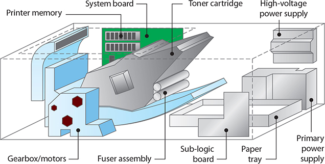
FIGURE 3.11-1 Components inside a laser printer
Laser Printer Components and Features
Here are the most important laser printer components and their functions:
• The imaging drum (or photosensitive drum) is a grounded cylinder with an ungrounded coat of photosensitive compounds. When light hits these particles, their electrical charge “drains” out through the grounded cylinder. Many laser printers use a toner cartridge (see Figure 3.11-2) that contains the imaging drum and, to simplify maintenance, most of the parts that suffer “wear and tear” and need regular replacing.

FIGURE 3.11-2 Laser printer’s toner cartridge contains the imaging drum.
• The fuser assembly is usually near the bottom of (but not included with) the toner cartridge and usually has two rollers (a pressure roller and a heated roller) to permanently fuse the toner to the paper. The heated roller has a nonstick coating such as Teflon to prevent toner from sticking.
• The transfer roller (transfer corona in older printers) applies a positive charge to the paper, so it in turn attracts toner particles from the drum. This positive charge also attracts the paper to the negatively charged drum, so a static charge eliminator removes the charge to keep the paper from wrapping around the drum.
• On single-pass color laser printers, a transfer belt is used to place all four colors (Cyan, Magenta, Yellow, and black) on the page at the same time.
• Paper is grabbed by the pickup roller from the paper tray or paper feed.
• The paper is then passed over a separation pad (CompTIA says separate pads) that uses friction to separate a single sheet from any other that were picked up.
• Printers with double-sided print capabilities also have a duplexing assembly, which flips the paper over after printing on the top side so the back side can be printed.
Laser printers have additional components. We will discuss these in the following section, which covers the laser print process.
Imaging Process
Knowing the imaging process helps you to troubleshoot printing problems. If an odd line is printed down the middle of every page, for example, you know there’s a problem with the photosensitive drum or cleaning mechanism, and the toner cartridge needs to be replaced. Here is the seven-step imaging process you need to know for the CompTIA A+ 220-1001 exam:
1. Processing
2. Charging
3. Exposing
4. Developing
5. Transferring
6. Fusing
7. Cleaning
Step 1: Processing the Image
When you click Print in an application, the CPU processes your request and queues the print job with the print spooler (an area of memory), causing the spooler’s printer icon to appear in the notification area. The operating system sends these jobs sequentially as the printer becomes available. Larger jobs must be broken into chunks first (which can take a while for huge documents), leaving documents further back in the queue waiting. The notification icon will go away when all jobs have gone to the printer—but you aren’t out of the woods yet.
Raster Images Impact printers receive data one character at a time, inkjet printers receive data one line at a time, but laser printers receive complete pages. If the page isn’t already a raster image, the printer’s raster image processor (RIP) rasterizes it to obtain a format the laser imaging unit can “paint” on the photosensitive drum. To accomplish this, the RIP needs enough memory (RAM) to process a full page.
EXAM TIP Insufficient memory usually causes memory overflow (“MEM OVERFLOW”) errors, in which case you can try reducing the resolution, printing smaller graphics, or turning off RET (see the following section for more on RET). Of course, the best solution is adding RAM to the printer.
Adding more RAM won’t solve every laser printer memory problem. Some data is just too complex for a RIP, as with a “21 ERROR” on an HP LaserJet, which indicates “the printer is unable to process very complex data fast enough for the print engine.” If the RIP is the limiting factor, reduce the complexity of the page image (use fewer fonts, less formatting, lower-resolution graphics, and so on).
Resolution Just like monitors, laser printers support different resolutions (adjusted down from the maximum the printer physically supports), with higher resolutions improving quality but requiring more memory. Common resolutions are 600 × 600 dpi and 1200 × 1200 dpi. The first number (horizontal resolution) reflects how finely the laser can focus, while the second number (vertical resolution) reflects the smallest increment the drum can turn.
Even at 300 dpi, laser printers produce far better quality than dot-matrix printers by using resolution enhancement technology (RET) to insert smaller dots that smooth out jagged curves (see Figure 3.11-3). RET uses more of the printer’s RAM, so disabling RET may free enough memory to complete the print job if you get a MEM OVERFLOW error.

FIGURE 3.11-3 RET fills in gaps with smaller dots to smooth out jagged characters.
CAUTION Printers may convert complex memory-intensive images to lower resolutions.
Steps 2–7: Printing the Image
Once processing (Step 1) is complete, the physical printing process can begin.
Step 2: Charging The primary corona wire or primary charge roller applies a uniform negative charge (usually between ~600 and ~1000 volts) to the entire surface of the drum (see Figure 3.11-4) so it can receive a new image.

FIGURE 3.11-4 Charging the drum with a uniform negative charge
Step 3: Exposing A laser (or LED) writes a positive image on the surface of the drum by forcing the photosensitive particles to release most of their negative charge.
Step 4: Developing Toner is a fine powder made up of plastic particles bonded to pigment particles. These less-negative particles attract toner because they are relatively more positive than the toner particles (see Figure 3.11-5).

FIGURE 3.11-5 Developing the image and applying the toner
Step 5: Transferring The transfer corona or transfer roller gives the paper a positive charge so that the negatively charged toner particles will leap from the drum to the paper.
EXAM TIP Color laser printers must apply four toner colors (CMYK), which they variously accomplish by sending each page through four one-color passes, or by placing all colors onto a special transfer belt before transferring them to the page in one pass.
Step 6: Fusing The mostly plastic toner particles are only attracted to the page—they still need to be fused to it. Two rollers—a heated nonstick roller and a pressure roller—melt the toner permanently into the paper. At this point, a static charge eliminator removes the paper’s positive charge (see Figure 3.11-6) so the printer can eject the page.
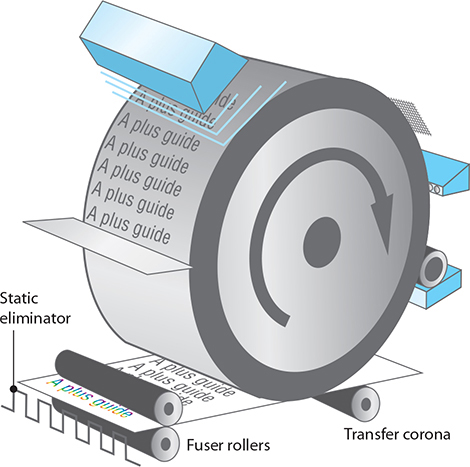
FIGURE 3.11-6 Transferring the image to the paper and fusing the final image
CAUTION The heated roller is hot enough to melt some plastic media such as overhead transparencies, which could damage your laser printer (and void your warranty); make sure to use media designed for laser printers.
Step 7: Cleaning Before a new page can be printed, the drum must be returned to a clean, fresh (physical and electrical) state (see Figure 3.11-7). A rubber cleaning blade carefully scrapes residual toner from the drum and deposits it in a debris cavity or returns it to the toner cartridge, and one or more erase lamps bombard the drum with light to neutralize all surface particles by draining any remaining charge into the drum.
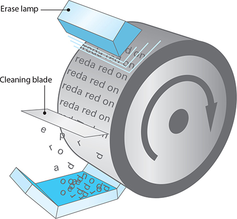
FIGURE 3.11-7 Cleaning and erasing the drum
NOTE Any damage done to the drum will show up on all prints until it is replaced.
Laser Printer Maintenance
Unlike computer maintenance, laser printer maintenance follows a fairly well-established procedure oriented around keeping it clean and following the maintenance schedule: replace the toner, apply the maintenance kit, and clean.
CAUTION All of the devices described in this objective have power supplies, but the corona in a laser printer requires extremely high voltage, making a laser printer power supply one of the most dangerous devices in computing! Turn off and unplug the printer as a safety precaution before performing any maintenance.
Over time, your laser printer builds up excess toner and paper dust or paper dander. Toner is hard to see—so the amount of paper dust is the best indicator a printer needs cleaning. If you can, take the printer outdoors and blow it out with a can of compressed air. If you must do it indoors, use a low-static vacuum designed for electronic components.
The printer’s manual will specify a cleaning process, but it often leaves out the rubber rollers that guide paper through the printer; these can slip and cause jams as they build up dirt and dust. Clean them with a small amount of 90 percent or better denatured alcohol on a fibrous cleaning towel. You can also re-texture slipping rollers and separator pads by rubbing them with a little denatured alcohol on a nonmetallic scouring pad.
CAUTION The photosensitive drum, usually inside the toner cartridge, can be wiped clean if dirty, but be very careful—a scratch will appear on every page printed until you replace the toner cartridge.
Replacing parts according to the manufacturer’s maintenance guidelines will help to ensure years of trouble-free, dependable printing from your laser printer. Here are the common tasks:
• Many laser printers or MFDs have maintenance kits that include everything you should replace on the same regular schedule, such as a fuser and one or more rollers or pads. You’ll typically reset the page counter so the printer can prompt you when it’s time again.
• Depending on the printer, you may clean (with an anti-static vacuum) or replace the ozone filter.
• Clean the fuser assembly with 90 percent or better denatured alcohol.
• A number of conditions require replacing the fuser assembly: pits or scratches on the heat roller (the Teflon-coated one containing a light bulb), an error code indicating the fuser is damaged or overheating (or merely that you’ve hit a preset replacement copy count), and failure of the thermal fuse that prevents overheating.
CAUTION The fuser assembly melts stuff for a living; always let it cool down first.
• Clean the transfer corona with a 90 percent denatured alcohol solution on a cotton swab. If the wire is broken, you can replace it; most snap in or are held in by screws.
• Paper guides can also be cleaned with alcohol on a fibrous towel.
Inkjet
Inkjet (or ink-dispersion) printers use a printhead connected to a carriage containing the ink cartridges (see Figure 3.11-8) or, on models that use refillable tanks, the printheads, to print on a staggering array of paper types.
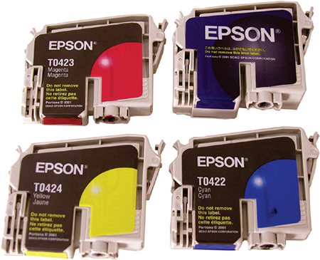
FIGURE 3.11-8 Inkjet ink cartridges
A belt and motor move the assembly back and forth to cover the page. A roller grabs paper from a paper tray (usually under or inside the printer) or feeder (on the top or back of the printer) and advances it through the printer (see Figure 3.11-9). The printhead uses tiny tubes with resistors or electroconductive plates at the end to boil the ink, creating a tiny air bubble that ejects a droplet onto the paper (see Figure 3.11-10). Print resolution, measured in dots per inch (dpi), indicates how densely the printer lays these droplets down, and high resolution is particularly important for images. Print speed is measured in pages per minute (ppm), and printers with monochrome and full-color modes typically indicate two speeds.

FIGURE 3.11-9 Inside an inkjet printer
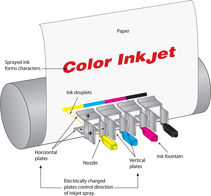
FIGURE 3.11-10 Detail of the inkjet printhead
NOTE A duplexing assembly is a built-in or add-on device that flips paper to enable automatic two-sided prints. It is a common feature in inkjet and laser printers and MFDs.
Calibrate
The term calibrate has two meaning with ink jet printers. In this section, calibrate refers to color matching the monitor output and printer output. When what you see on your monitor and what prints differ significantly, monitor color calibration hardware generates an International Color Consortium (ICC) color profile that defines the color characteristics of the hardware so the OS can correct for any difference between the intended and displayed colors. Color profiles can also document the quirks of a specific printer; you can find them on the installation media, purchase one separately, or generate your own. Combined, calibrating all of your imaging devices helps harmonize what you see onscreen and on paper with the file’s image data.
NOTE Windows includes Windows Color System (WCS) to help build color profiles for use across devices. WCS is based on a newer standard Microsoft calls color infrastructure and translation engine (CITE).
Inkjet Maintenance
Inkjet maintenance includes cleaning heads, replacing cartridges, calibrating, and clearing jams. Inkjets generally have built-in maintenance programs that you should run from time to time to keep your inkjet in good operating order (see Figure 3.11-11). It may be hard to find; check Printing Preferences, the Start menu, and any printer management web page.

FIGURE 3.11-11 Inkjet printer maintenance screen
• When do you need to clean printheads? Ink inside the printhead nozzles has a tendency to dry out and plug them. If your printer is telling Windows that it’s printing and feeding paper through, but either nothing is coming out (usually the case if you’re just printing black text) or only certain colors are printing, the culprit is almost certainly dried ink clogging the nozzles. You can start the process by pressing hardware buttons or through the printer preferences menu—but just do this as needed because it uses a lot of expensive ink.
• Inkjet cartridge replacement varies widely from printer to printer—refer to the printer’s documentation (some printers use ink reservoirs rather than cartridges). Typically you’ll open a compartment on the printer and see one or more cartridges attached to the printhead. If you can’t reach them, the printhead should move into an accessible position if the printer is on (don’t try to force it out). They may just slide into place, but many printers have clips or slots (along with indicators for which cartridge goes where). Check the new cartridge for a piece of tape or other covering on its nozzles and contacts. Make sure you have everything properly seated and clipped before you close the lid—these parts can catch on other components when the printhead moves.
• Inkjets typically have a routine to align or calibrate the printheads, which can fix poor output; the printer spits out a test page, and you either manually select the best result or, on an MFD, place it on the scanner as instructed.
• Aside from the usual suspects, an inkjet may pick up too many sheets if it is overheating, so let it cool down if you have been cranking out documents.
• If your printer has an ink overflow tank or tray to catch excess ink from the cleaning process, check it from time to time—an overflow onto electrical components is predictably bad. Put on some latex or vinyl gloves and stick a twisted paper towel into the tank to soak up most of the ink. The ink is water based, so dampen a paper towel with distilled water to clean any spilled ink.
EXAM TIP Make sure you understand how inkjet printers operate and how to maintain them.
Thermal
Thermal printers use a heated printhead to create a high-quality image on special or plain paper. Two types exist:
• Direct thermal printers Use a heating element to burn dots into the surface of special thermal paper; these are often seen in retail receipt printers with large rolls of thermal paper housed in a feed assembly that automatically draws the paper past the heating element.
• Thermal wax printers Work like dye-sublimation printers, but the film is coated with colored wax—no special paper required (though quality suffers because they use dithering, unlike dye-sublimation printers).
Thermal Printer Maintenance
Direct thermal printers only need occasional cleaning and paper replacement. Turn off the printer and open it according to the manufacturer’s instructions; remove debris and then use denatured alcohol and a lint-free cloth to clean the heating element. Clean the rollers with a cloth or compressed air so they can properly grip the paper. To replace the paper, slide off the old roll, slide on the new one, and feed the paper through the heating element.
Thermal wax printers also need wax ribbon replacement, which is similar to replacing the roll of paper; make sure to feed it past the heating element. Your printer should include instructions for installing a new ribbon.
Impact
Impact printers create an image by physically striking an ink ribbon against the paper’s surface, making them relatively slow and noisy. Impact printers are largely gone from our homes, but one kind—dot-matrix printers—are still common in businesses because they can print to multipart forms. Point-of-sale (POS) machines, for example, use special impact paper that can print two or more copies of a receipt. Dot-matrix printers (see Figure 3.11-12) have a printhead holding pins or print wires that strike the inked ribbon, and many use tiny sprockets to advance tractor-feed impact paper. Draft-quality printheads use 9 pins (some high-speed models use 18-pin printheads), whereas near-letter-quality (NLQ) printheads use 24 pins.

FIGURE 3.11-12 Inside of an impact printer
Impact Printer Maintenance
Impact printers are near-immortal with diligent regular maintenance:
• Keep the platen (the roller or plate the pins strike against) and printhead clean with denatured alcohol.
• Lubricate gears and pulleys (but never the printhead) to specification.
• Replace the ink ribbon every so often.
• Replace the printhead if it becomes damaged.
Most impact printer paper feeds continuously from a roll or ream, so to replace the paper, you’ll need to swap out the rolls or move the new ream into position, feed out any remaining paper, and feed in the new paper. Paper quality, debris, and improper feeding can lead to jams, which you typically clear by feeding the paper one way or the other.
CAUTION Check the printer’s documentation first; steps to feed paper on one impact printer can easily break the feeding system on another.
Virtual Printers
The virtual printer doesn’t look like much, but it’s still pretty similar to “real” printing. When you print to one, your system goes through all the steps to prepare the document for printing and then sends it off to a virtual printer program that converts the output from your computer into some other format and saves the result to a portable file that looks like the printed page would. It’s a quick way to save anything you can print. Let’s look at the virtual printers that CompTIA expects you to know for the exam.
EXAM TIP Make sure you understand the differences between the different virtual printer methods.
Print to File
Print to file, which produces a file that can be later printed without access to the program that created it, but this is a legacy option (you’ll often see it as a checkbox on your print screen) that may not work well with USB printers and produces files that are hard to work with. Use one of the other options instead.
Print to PDF
Almost every OS can print to PDF files out of the box these days. However, Windows didn’t join the party until Windows 10, so you’ll need to install a virtual PDF printer on older versions of Windows. You can get one through official Adobe software or a third party.
Print to XPS
Windows versions since Vista include the Microsoft XPS Document Writer, which creates an .xps file you can later open with the included XPS Viewer. Support in other operating systems varies, but most have third-party software available for working with XPS files. Unless you need an XPS file, a PDF file is a lot more useful with a lot more programs.
Print to Image
This lets you save a regular image file, such as BMP, GIF, JPG, PNG, TIFF, and more. Image formats aren’t the best for documents—text won’t scale well and can’t be easily searched/selected/copied, for example—but they are very portable. You will generally need a third-party virtual printer to print to the desired image format on a given OS.
3-D Printers
A new topic introduced in the CompTIA A+ 1001 exam objectives, 3-D printers are showing up in more and more places. 3-D printers turn 3-D designs into physical objects. They are used for prototyping, custom manufacturing, and modeling of 3-D objects for classrooms and for recreation.
3-D printers use melted material to create prints of three-dimensional objects. Although some 3-D printers use metal powders, the ones you are most likely to encounter in classrooms, maker spaces, and libraries use plastic filament.
3-D Printer Maintenance
The most obvious maintenance issue for a 3-D printer is the installation of the appropriate plastic filament for the printer and the print job.
ADDITIONAL RESOURCES To learn more about filament types, check out the https://3Dprintmanual.com website.
Beyond filament replacement, there are maintenance kits available from many 3-D printer vendors to help keep their printers working properly. Some maintenance kit features include
• Replacement Bowden tube (used by 3-D printers that have the stepper motor on the frame rather than on the printhead itself)
• Lubricant for moving parts
• Calibration card
• Nozzles
• Cooling fans
REVIEW
Objective 3.11: Given a scenario, install and maintain various print technologies
• Laser printers use electro-photographic imaging (known as the EP process) to print.
• The key components of a laser printer are imaging drum, fuser assembly, transfer belt, and transfer roller.
• Paper feed components on a laser printer include pickup roller, separation pad, and duplexing assembly.
• The laser printer imaging process has the following seven steps in order: processing, charging, exposing, developing, transferring, fusing, and cleaning.
• Laser printer maintenance includes replacing toner, applying a maintenance kit, calibrating the printer, and cleaning it.
• Inkjet printers use heated ink to place droplets on paper or media to print.
• Key inkjet printer components include ink cartridge, printhead, roller, feeder, duplexing assembly, carriage, and belt.
• Calibrate has two meanings: color matching between displays and the printer (in the context of inkjet printing), or the alignment process that is periodically recommended to make sure the printhead is printing straight vertical lines and properly formed text.
• Third-party ink should be evaluated carefully for color quality, durability, and whether it clogs printheads.
• Test prints and printhead cleaning routines help find and fix clogged printheads.
• Thermal printers use a heated printhead to print using special thermal paper or to transfer an image from a thermal wax ribbon to standard paper.
• Key components of a thermal printer include feed assembly and heating element.
• Thermal printer maintenance steps include replace paper, clean heating element, remove debris.
• Impact printers print from an inked ribbon onto single-part or multipart paper using printhead pins or wires to make a dot-matrix grid that forms letters, numbers, and shapes.
• Key impact printer components include printhead, ribbon, and tractor feed.
• Maintenance steps for impact printers include replace ribbon, replace printhead, replace paper.
• Virtual printers are software programs accessed through the printer (or occasionally the File | Save As) menu. They can save print jobs as files in PDF, XPS, and popular graphics formats such as TIFF, JPEG, and others.
• 3-D printers use a variety of plastic filament or other thermal materials to turn 3-D images into physical objects.
• The most common 3-D printer maintenance issue is filament replacement, but lubrication and replacement of tubes and print nozzles are also needed periodically.
3.11 QUESTIONS
1. Your client asks you to pick up some filaments before coming over to service the printer. What type of printer does your client have?
A. Laser
B. 3-D
C. Inkjet
D. Virtual
2. A direct thermal printer does not use which of the following in the print process?
A. Ribbon
B. Special thermal paper
C. Feed assembly
D. Heating element
3. You are trying to determine why a laser printing is leaving loose toner on the paper that looks like the print job but falls off the paper. Which of the following is the most likely cause?
A. Processing failure
B. Defective toner cartridge
C. Fuser failure
D. Paper feed failure
4. A user in your department is frustrated because his 20-page report is only printing on one side of the paper, and he must make 40 copies. Which component in the printer is either not enabled or not working?
A. Paper feed
B. Duplexing assembly
C. USB
D. Toner cartridge
5. A bottle of 90 percent or better denatured alcohol is a versatile cleaning product for printers. However, it should not be used to clean everything. From the following list, which item should not be cleaned with denatured alcohol?
A. Transfer corona
B. Platen
C. Impact printhead
D. Ink ribbon
3.11 ANSWERS
1. B Filaments are used in 3-D printers.
2. A A direct thermal printer prints directly onto special thermal paper. A thermal transfer printer uses a heat-sensitive ribbon to print onto plain paper.
3. C A fuser failure will cause the printed image to not stick to the paper.
4. B The duplexing assembly is used to print on both sides of the paper.
5. D If the ink ribbon is worn or faded, replace it.