
Chapter 12
Multifunction Airborne Antennas1
12.1. Introduction
In the areas of detection, communications and electronic warfare, the various functions that modern airborne platforms should fulfill require the installation of numerous antennas on carriers with reduced size and limited available space.
It should also be noted that these functions operate on a frequency band globally spreading from the VHF band to the Ka band, and that the Fields of View around the carrier, the radiation patterns and the polarizations to radiate are specific to each of these functions. The physical integration of these aerials into the carrier is therefore an extremely difficult challenge, emphasized by the requirements regarding constraints on couplings between aerials (EMC) and by financial considerations.
One possible way to overcome this complexity is to gather a maximum number of radiating functions over a minimum number of aerials optimally positioned on the aircraft. This operation of gathering functions is evidently only possible if there is no simultaneity for functions shared on a single aerial, and if the radio-electric performance of any aerial is adequate to fulfil the different requirements for each radiating function it is supposed to serve.
The technique of active array antennas, which consists of distributing the RF amplifiers in proximity of the radiating elements, is particularly adapted to the design and development of multifunction antennas, as it gives way to the realization of extremely complex microwave functions.
After a brief summary of present and future needs for airborne platforms, we give the main characteristics for the technique of active antennas (active electronically scanned array – AESA – antennas) developed for airborne applications. We describe subsequently the evolutions this technique should follow in order to provide a multifunction capacity (MAESA) for radar, electronic warfare and communication.
Finally, before concluding, a section succinctly describes the main axis future work and research should follow.
12.2. Functions performed by the principal sensors of a fighter aircraft
The perfect execution of missions devoted to fighter aircrafts requires sensors ensuring active and passive detection of menaces, means for target identification, and means for self-protection as well as means for navigation and for short and long range communication.
It should be noted that these various means have specific requirements in terms of:
– frequencies and frequency bandwidths;
– radiated power;
– sensitivity;
– radiation patterns, angular coverage and polarization;
– operational time periods and durations (while in mission).
But it should also be noted that they all require antennas with directive and agile radiation beams, which are complex and usually uneasy to implement on fast and/or small size aircrafts.
Moreover, present and future evolutions for systems generate new requirements and needs, among which:
– detection of small RCS low profile and low contrast targets;
– management of radiated power;
– operation of bistatic or multistatic modes;
– operation of mono- and/or multi-carrier passive modes;
– active control of carrier signature;
– protection against high power RF signals;
– etc.
These new requirements lead to the improvement of the capacities of present sensors, and to an increase in their number.
12.3. Technique of active antennas
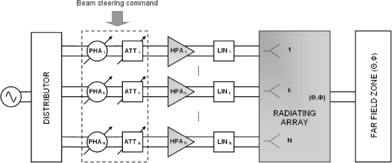
The definition of the technique for active antennas integrated in the development of modern radars is illustrated in Figure 12.1.
Figure 12.1. Block-diagram of an active antenna
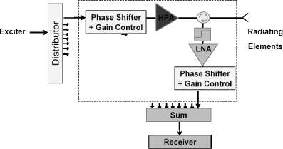
The RF signal to be transmitted is divided into N microwave channels, each of which is equipped with an amplitude and phase control device for the signal which is then amplified right before being sent toward the radiating element of this channel.
The N reception channels are isolated from transmission channels by circulators positioned between the radiating element and the high power (HPA) and low noise (LNA) amplifiers.
The technique of active antennas present numerous advantages compared to mechanically scanned antennas, namely: the capacity to radiate high RF power, the high flexibility for radar modes (management of radiated power, bandwidth, management of radiation patterns in transmission and/or reception, polarization control, etc.) as well as the reliability brought, on the one hand, by the suppression of all mechanical movement, and on the other hand by the parallelization of a high number of active channels (notion of soft degradation).
However the drawbacks of this technique are closely linked to the complexity of its structure, giving way to antennas with possible high mass and volume.
Figure 12.2 shows the structure of an active antenna for a fighter aircraft, designed to be positioned in the front position behind a radome which must exhibit a high degree of radio-electric transparency and good aerodynamic characteristics.
Figure 12.2. Active antenna for fighter aircraft
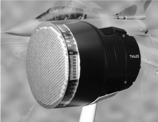
The introduction of additional functions complementary to those of the aircraft front nose will only be possible if they involve antennas with depths compatible with installation on the final carriers. Hence a supplemental major constraint is to design antennas with reduced thickness.
12.4. Multifunction antennas
The need to integrate an ever greater number of complex antennas, under the constraints of:
– performance of the various equipments;
– operational agility bandwidth and instantaneous bandwidth;
– operational angular coverage around the carrier;
– control of costs;
– reduced available locations (balconies) on the aircraft;
– control of radar signature;
– compatibility with other equipments;
supports the design and development of multifunction antennas, i.e. antennas no longer dedicated to a single application, but that could be shared and used simultaneously or not by various equipments for radar, electronic warfare and communication.
Figure 12.3. Concept of multifunction antenna for fighter aircraft
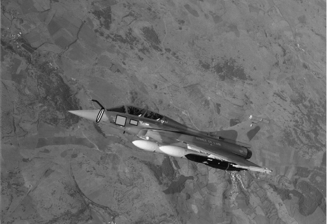
An example of what could be a multifunction antenna is illustrated in Figure 12.3 with the two lateral panels at cockpit level. Such an antenna covering a broad frequency band, e.g. the 6 GHz – 18 GHz bandwidth, could provide the following functions:
– extension of the angular coverage for the air-to-air modes of the front radar;
– air-to-ground modes: SAR/MTI;
– self-protection jamming;
– high sensitivity ELINT;
– aircraft-to-missile links;
– intraflight and/or Satcom links.
Hence, it is the design and development of a technique for active broadband multi-polarization and compact antennas which is at stake. The choice for architectures and technological solutions will have to answer these requirements.
12.4.1. Antenna architecture
12.4.1.1. Assembling technology
Wideband active antennas have been developed for some years with a “brick” architecture, i.e. making use of printed circuits positioned orthogonally to the radiating aperture and longitudinally with respect to the propagation of the RF signal to radiate. This disposition favors the design of broadband antennas, but presents the inconvenience of leading to bulky antennas.
Instead we will use another assembling technology, the “tile” architecture, making the antenna a multilayer printed circuit sandwich.
It is then possible to design and develop very compact antennas, albeit with a maturity level way behind that of “brick” architecture.
In addition to the difficulties generated by the high density of circuits inherent to this disposition, a further difficulty arises from the necessity to ensure the routing of the various signals (microwave, DC supplies, logic) between the different layers of the sandwich.
12.4.1.2. Allocation of transmit/receive functions
Another important criterion lies in the allocation of transmission and reception functions among the various antennas of the different equipments corresponding to the different functions. The classic solution consists of using one transmit/receive antenna for each sensor, and positioning all these antennas on the carrier.
In the case of a multifunction antenna, the analysis shows that it is preferable to gather every transmission function within a transmission antenna, and every reception function within a reception antenna. This new kind of allocation presents many advantages, the most important ones being:
– the sizes of transmission and reception antennas may be different;
– the frequency bandwidths for transmission and reception may be different;
– the cooling system may be designed for each function;
– the possibility to simultaneously transmit and receive;
– the reduced density of microwave circuits inside each antenna;
– the devices used to separate transmit and receive channels are no longer necessary;
– the isolation problems between transmission and reception are greatly reduced.
This kind of allocation should offer more possibilities/opportunities to manage the various modes of the MAESA antenna, as it removes the strong constraint for a classic antenna which cannot receive while transmitting. It should finally be noted that this disposition seems more favorable to the application of bistatic or multistatic modes in scenarios with multiple carriers.
A disadvantage lies however with the necessary duplication of some microwave functions (components, PCBs, surface on the platform, etc.), which may become a difficulty for the design case of small antennas to be located on small carriers (UAV).
12.4.1.3. Multiple polarization
In order to answer a maximum number of needs, the multifunction antenna should be able to radiate two orthogonal independent polarizations: (H, V). Generally, this requirement is a strong constraint as it necessitates the fitting of two transmit/receive channels within the elementary mesh of the active array antenna. This is a strong cost driver, and may even become impossible to design at high frequencies.
Figure 12.4. Dual-polarization architectures
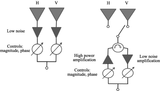
It should be noted however that separating transmission and reception functions liberates room within the elementary mesh, and that it is not always mandatory to operate simultaneously on both polarizations, even in multifunction operation. Candidate solutions to diminish these constraints would either be the use of a switch to select the appropriate polarization, or the separation of the transmission and reception channels according to the diagrams in Figure 12.4.
12.4.2. Dual-polarization antenna
Figure 12.5 shows the picture of a “checkerboard” antenna mock-up operating in a broad frequency band (Fmax/Fmin=3) with dual linear polarization, and achieved in tile technology [HER 03, DRA 88].
Figure 12.5. Wideband antenna with dual linear polarizations
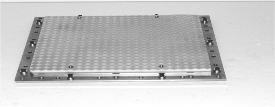
The radiating face consists of a self-complementary pattern of metal patches arranged as a “checkerboard”. The excitation of the radiating plane is performed with dual linear wires positioned on either side of each vertex of the patches, generating two orthogonal and independent polarizations (±45°). This type of radiating structure presents the prominent advantage of exciting each polarization at different places on the antenna, which significantly simplifies its design, particularly at high frequencies.
Note that, unlike classic solutions, all radiating patches of this antenna are connected to each other, and therefore cannot be considered as isolated radiating elements. It is this property that allows in particular the excitation of wavelengths way above the size of an elementary patch, and therefore the design of arrays operating over a wide frequency band. This property is also exhibited by other structures, under the generic name “connected arrays” [TAY 03].
The cross-section view of the complete active antenna is presented in Figure 12.6. Besides the radiating plane, it exhibits two multilayer circuits (baluns) ensuring impedance match between radiating patches and active circuits, and balancing the excitation towards the patches.
Figure 12.6. Cross-section view of a wideband dual polarization antenna
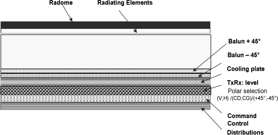
Then there is a cooling plate ensuring heat control for the RF active modules, the transmission (Tx) and reception (Rx) active channels, and the circuits used to tune the amplitude and phase for each channel in order to calibrate the antenna, select the polarization and steer the radiated beam in the appropriate direction. Finally, one or multiple RF manifolds are used to combine the microwave signal, collected by radiating elements, amplified and phase shifted, at sub-array level (notion of building block). According to the detailed design of the multifunction sensor (frequency bandwidth, angular scan coverage, spatial resolutions, etc.) this signal may then be digitized and exploited in the different reception channels.
The design of very wideband array antennas deals with two contradictory constraints regarding the size of the radiating elements.
As a matter of fact, one major constraint for an array antenna is the necessity to respect a mesh size (distance between radiating elements) less than half a wavelength at the maximum frequency of operation, in order to avoid the appearance of grating lobes. The capacity to respect this constraint directly depends on the technologies used for the active and passive microwave circuits equipping each channel.
This reduced mesh size infers the use of radiating elements with excessively small dimensions for the lower part of the frequency band, leading to poor efficiency. The “connected array” architecture mentioned above gets rid of this limitation by having many radiating elements involved in the radiation.
Figure 12.7. Radiating face of a 2.5 GHz – 10 GHz antenna

The radiating face of a 2.5 GHz – 10 GHz antenna (Fmax/Fmin=4) is presented in Figure 12.7. The grey squares represent the metal radiating patches, while the red and blue arrows respectively indicate the feeding points for −45° and +45° polarizations. The continuous line frame indicates the dimensions of the elementary mesh, inside which the microwave circuits should fit, if necessary positioned on different layers.
12.5. Model for the antenna
The design and development of such an antenna can only be accomplished with high-performance electromagnetic simulation software tools, able to take into account the entire multilayer structure forming the antenna.
It was mentioned previously that the mesh size, which can be allowed for upper frequencies, makes up a major limitation. It was also noticed that partitioning the transmission and the reception functions of a multifunction sensor over two distinct antennas offered many benefits. In these conditions, the presence of an otherwise bulky circulator is no longer necessary. However the role of a circulator is not only to separate transmission and reception channels, but also to isolate active elements from the effects of the antennas active VSWR. Hence, it is important to be able to predict and estimate the appropriate isolation level between the radiating array and the RF amplifiers for the correct operation of a large size active array antenna, particularly when the amplifiers operate in nonlinear regime. This subject has been treated in Romier’s PhD thesis [ROM 08].
Figure 12.8. Model used in transmission
The diagram in Figure 12.8 represents the model used in transmission. It allows us to take into account the couplings between the radiating elements of the array, the saturation level of the amplifiers and the potential mismatch of the amplifiers due to the active VSWR presented by the radiating array with respect to frequency and angular scan command.
The development of such a model first requires the use of a model for HPAs valid in the nonlinear regime. In this perspective, we have relied on the poly-harmonic distortion model, in which incoming and outgoing waves to and from the amplifier are linked by the following relations [VER 06]:
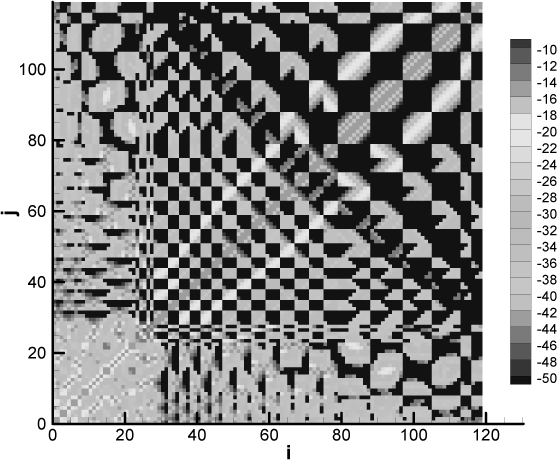
The various elements of this matrix have been measured in a nonlinear regime. The S matrix of the array, indicating in particular the couplings between the radiating elements, is presented in Figure 12.9 for an array restricted to 119 radiating elements. The greyscale code indicates in dB the square of each Sij modulus.
Figure 12.9. S matrix for an array of 119 radiating elements
An iterative computation process has therefore been developed in order to solve the global problem. It makes use of the partial matrices of all the elements indicated on the model in Figure 12.8, and in particular the adjustable elements controlling the amplitude and phase of each channel. Once this matrix is obtained, the radiation pattern of the array with respect to frequency, scan angle, etc. may be calculated. Figure 12.10 compares the radiation patterns, which would be obtained in linear regime and in saturated regime (3 dB), for a 30° scan angle referenced in the broadside direction.
Figure 12.10. Radiation patterns
12.6. Potential prospects
The aforementioned concepts will still have to undergo many developments before they may be implemented in airborne equipments. In order to do so, there should be further work in the domain of very wideband arrays: architecture of the arrays, reconfiguration of the antennas, optimization of the multilayer dielectric stack, active baluns, polarization control, etc. As an example, the dielectric substrates used in wideband printed antennas might generate propagating surface waves at the origin of scan blindness for some scan angles and frequencies. Passive or active metamaterials should eventually bring worthwhile development capacities.
The architecture of such antennas relies on the availability of very compact but numerous microwave circuits, as they must fit the elementary mesh size designed for the upper operating frequency of the antenna. Within this framework, optimal integration of active functions should be pursued in order to obtain correct operation at high frequencies while controlling costs.
Finally, it is of prime importance to carry on developing electromagnetic simulation tools, essential to the design of active antennas and particularly multifunction active antennas.
12.7. Conclusion
Active antennas have proven a high level of radio-electric performance, in terms of EIRP and capacity for beam agility and flexibility of operation modes. As such, they are an invaluable and necessary technology.
However their performance may still be largely improved with additional developments in the following domains:
– cost reduction with integration of functions;
– reduction of mass, volume and power;
– broadening of radio performance: frequency bandwidth, agility, etc.;
– improvement of physical integration inside the carriers superstructures (drones);
– RF signature control, etc.
In this context, the development of MAESA antennas aims at:
– reducing the mass and volume of AESAs;
– improving the performance of airborne sensors;
– allowing the introduction of new functions otherwise impossible to fit on small size carriers (UAV).
12.8. Bibliography
[DRA 88] DRABOVITCH S.S., CASSEAU D., RÉSEAU d’éléments rayonnants à topologie autocomplémentaire, et antenne utilisant un tel réseau, French Patent 88–12955, October 4, 1988.
[HER 03] HERAULT J., “Antennes conformes aéroportées”, STTC (French MoD) contract, 2003.
[ROM 08] ROMIER M., “Simulation Electro-Magnétique des antennes actives en régime non linéaire”, PhD Thesis, Institut National Polytechnique Toulouse, France, 2008.
[TAY 03] TAYLOR R.C., MUNK B., DURHAM T., Wideband phased array antenna and associated methods, US Patent 6,512,487 B1, January 28, 2003
[VER 06] VERSPECHT J., ROOT D., “Polyharmonic distorsion modeling”, IEEE Antennas & Propagation Magazine, June 2006.
1 Chapter written by Christian RENARD, Maxime ROMIER and Michel SOIRON.