
Chapter 8: Virtual Private Networking
This chapter will explore the Virtual Private Network (VPN) technologies available on the OPNsense core: IPsec and OpenVPN. With OPNsense, you can connect securely to remote sites and users using site-to-site and remote user deployments, and we'll learn how to do it in this chapter. After reading this chapter, you will be able to deploy VPNs using OPNsense, connecting remote networks and users in a secure manner.
We will explore the following topics in this chapter:
- OPNsense core VPN types
- Site-to-site deployments using IPSec
- VPN deployments using OpenVPN
Technical requirements
For this chapter, you need to know how to create firewall rules on OPNsense and read logs using a Command-Line Interface (CLI). Practicing the example configurations will require knowledge about creating virtual machines on VirtualBox, or other virtualization environments, to connect to OPNsense. Basic knowledge about certificates and cryptography is recommended.
OPNsense core VPN types
Virtual private networking enables remote networks to connect through WAN connections using cryptography to protect data exchanged inside a tunnel. It is a fundamental concept of VPNs, but we can extend it in scenarios that demand data protection using cryptographic mechanisms.
OPNsense in a stock installation supports two types of VPN technologies: IPsec and OpenVPN.
IPSec
The Internet Protocol Security (IPsec) protocol implements authentication and encryption of data over the IP protocol. It is a prevalent protocol when compared with other VPN technologies such as OpenVPN, for example. So, while connecting OPNsense with other firewall technologies, especially the closed source ones, IPsec will be the first option you should consider. This type of VPN is most commonly used to connect remote networks utilizing a site-to-site deployment. We will explore the possible deployments on OPNsense later in this chapter.
OpenVPN
OpenVPN is an open source protocol that uses the OpenSSL library to implement cryptography. It is a popular solution for open source projects, so with OPNsense, it isn't different than other open source firewall projects. As a flexible protocol, it is based on Transport Layer Security (TLS) and is commonly used in both site-to-site and remote user deployments.
IPsec versus OpenVPN
If you are not familiar with these technologies, you are probably thinking, When should I choose one or another VPN technology? Let's explore this by getting to know the pros and cons of each protocol.
The pros of the IPsec protocol are as follows:
- As fast as it gets: An IPsec tunnel doesn't demand powerful hardware to get a good connection performance once it runs on the IP protocol (layer 3). This protocol will work well once both VPN tunnel sides have a WAN connection with decent speed and network latency.
- Compatibility: Most modern firewalls support IPsec, so it is a widespread protocol for VPNs.
The cons of the IPsec protocol are as follows:
- Tricky configuration: It isn't rare to spend hours and hours getting an IPsec tunnel up and running. It's common for it to happen while trying to connect different firewall technologies.
- NAT unfriendly: Some devices don't support IPsec traversing NAT, so when traffic goes through connections using NAT, you will probably face issues while using IPsec. For this reason, connecting remote users using IPsec will likely be more complex than using OpenVPN. This is actually a NAT issue that breaks transported protocols by manipulating packet headers.
- Different Internet Key Exchange (IKE) versions (v1 and v2): If both devices aren't using the same IKE version, getting the tunnel up and running will not be possible.
Note
You can read more about IPsec NAT issues here: https://www.uninet.edu/6fevu/text/IPSEC-NAT.SGML.html.
Now, let's look at OpenVPN's pros and cons.
OpenVPN's pros are as follows:
- Flexibility: OpenVPN can operate in most WAN connection scenarios without issues no matter what connection technology is being used, given that it has a decent speed and latency. Even with several NAT rules being applied to the traffic, it is a good option, especially while connecting remote users. The client-server design permits better support to multi-WAN connections or those that don't have public IPs on one of the VPN endpoints.
- Better control features: OpenVPN has more control features while using remote users' connections than IPsec has. The client-server design used by OpenVPN allows controls to be applied on the client (user) side. It is possible to push routes and other commands to clients without any user-required action; this is a considerable advantage while managing hundreds, or even thousands, of users.
- Cost-effective and better security: There are free OpenVPN clients for the most common operating systems (Windows, Linux, macOS, FreeBSD, and mobile platforms such as Android and iOS). So, if you need to implement a VPN solution with excellent security at a low cost, OpenVPN will probably be the best option. For remote user (also known as road warrior) deployments, OPNsense even supports Two-Factor Authentication (2FA) natively.
Note
An excellent example of fine-grained control of the client side using OpenVPN is blocking Windows users from using an external DNS server while connected to an OpenVPN tunnel. Details about this feature and how it was implemented on OPNsense can be found here: https://github.com/opnsense/core/issues/4422.
OpenVPN's cons are as follows:
- Hardware consumption on high loads: OpenVPN needs decent hardware with some crypto acceleration onboard to perform well on high-speed demanding tunnels. You must pay this price to have OpenVPN as a VPN solution in larger network environments; otherwise, if you connect small networks with low-speed demanding traffic on a tunnel, any modern hardware will work very well.
- Requires additional software installation: Compared to IPsec, which has a native client on Windows, Android, macOS, and iOS, for example, OpenVPN demands software installation to work, which can become an issue at the deployment phase with dozens of users; it may require a lot of work and planning to deploy access to all users.
As we can see, there are pros and cons for both VPN technologies, and based on my personal experience, I can tell you that you'll need both running on your OPNsense installations most of the time so you will be able to choose which one better suits your network demands.
Now, let's look at the possible deployments we can do using these two protocols.
Site-to-site deployments using IPsec
This deployment type is commonly used to connect remote networks: for example, a branch office to a head office. In the past, it was common to use private lines/WAN connections based on Multiprotocol Label Switching (MPLS) and frame relay, for example. Nowadays, with large offers from ISPs of high-speed WAN connections, it is cost-effective to use a site-to-site VPN solution rather than contracting a private line service.
An example of multiple site-to-site VPN tunnels connecting branch offices to a head office is shown in the following diagram:

Figure 8.1 – Site-to-site VPN topology example
As we can see in the preceding diagram, the communication between the company offices is made by using the internet but protected by a VPN tunnel.
On OPNsense, we can use IPSec or OpenVPN to create a site-to-site tunnel. Let's see what the options are while creating an IPsec tunnel using the webGUI.
Note
We won't cover a complete lab setup here, but you can create two OPNsense virtual machines using VirtualBox or try any other public cloud service to practice it. Many cloud providers offer a free trial period, which you can use to create a lab and practice some of the steps shown in this book.
The OPNsense official documentation has many recipes for configuring site-to-site and remote users (called Road Warriors in OPNsense documentation). You can find it here: https://docs.opnsense.org/manual/vpnet.html#ipsec.
A typical IPsec site-to-site topology will look as follows:

Figure 8.2 – Typical site-to-site IPsec topology
Before starting to investigate the OPNsense webGUI options, let's review some essential concepts about IPsec tunnels:
- Phase 1: In this first phase, the IKE protocol will exchange messages between the two gateways (also known as peers) to ensure an encrypted channel to start the phase 2 negotiation. On the OPNsense, webGUI will be in the phase 1 parameters that the gateways IP addresses will be defined.
- Phase 2: After phase 1 is successfully completed, the IPsec gateways start to negotiate phase 2, where the gateways define which networks will be allowed to send traffic into the tunnel, and how to authenticate and encrypt traffic, for example.
Now that we have explored the IPsec basics, let's see how to set a tunnel using the OPNsense webGUI:
- Go to VPN | IPSec | Tunnel Settings.
- Click on the + button to create a new IPsec phase 1 tunnel. After clicking on it, a new page will be shown with the tunnel settings.
- Disabled: Click on this option to disable this phase 1 tunnel.
- Connection method: Select one of the following options:
- Default: This, by default, will behave like the Start on traffic option, as explained later in this list.
- Respond only: This option will load the phase 1 connection without starting it. This option is recommended while using the Common Address Redundancy Protocol (CARP).
- Start on traffic: This option tells the IPsec service to load this phase 1 connection and as soon as traffic is detected between gateways, the connection is established.
- Start immediate: When set, this will start up the tunnel immediately, ignoring the connection.
- Key Exchange Version: Set the IKE protocol version that will be used in this connection. You can select auto, which will use IKEv2 (V2) as default, V1 to force the use of IKEv1, or V2, which will set it to IKEv2.
- Internet Protocol: Select which IP protocol family will be used in this phase 1 tunnel: IPv4 or IPv6:
- Interface: Select which network interface or virtual IP will be used for this IPsec tunnel.
- Remote gateway: Type the IP address or hostname of the remote gateway the tunnel is connecting to. You will probably want to choose the OPNsense WAN interface here.
- Dynamic gateway: Check this option when another tunnel endpoint is using a dynamic IP address. This option will usually be required when the remote gateway option is set with a dynamic DNS hostname.
- Description: Provide a description of this IPsec tunnel.
- Phase 1 proposal (Authentication): The following options are authentication-related. Pay attention to specify precisely the same on both tunnel gateways:
- Authentication method: Select which authentication method will be used by both tunnel sides. For site-to-site tunnels, you'll want to choose a mutual Pre-Shared Key (PSK) here. For better security, prefer using certificates instead.
- My identifier: This option will be used to identify the peer and associate it with this tunnel on the remote side.
- Peer identifier: This option will define how the remote peer will be identified in this tunnel by OPNsense. It is common to use the default option, Peer IP address, but it will depend on the configuration used by both tunnel sides.
- Pre-Shared Key: This is the string used by both tunnel sides to authenticate, so choose something strong to keep this tunnel safe. It is a good practice to exchange this string out of band (by phone call, for example).
Tip
You can use the OPNsense CLI to generate a strong PSK; an example is using the openssl rand -base64 48 | tr -dc '[:alnum:] ' OpenSSL command.
Phase 1 configuration
Phase 1 proposal (Algorithms) contains the following options that will define which encryption algorithms will be used in the tunnel proposal phase. Always check on both tunnel endpoints whether the options are precisely the same:
- Encryption algorithm: This option must specify which encryption algorithm will be used by both tunnel endpoints. It is recommended to use strong algorithms such as Advanced Encryption Standard (AES 256) instead of deprecated ones such as Triple Data Encryption Algorithm (3DES).
- Hash algorithm: Select which hash algorithms will be used in this tunnel. You can select multiple algorithms. Using more robust hash algorithms such as SHA256 or higher is recommended to have a good level of security.
Note
Avoid using deprecated hash algorithms such as MD5 and SHA-1. More details can be found at the following page:
3DES deprecation NIST: https://csrc.nist.gov/news/2017/update-to-current-use-and-deprecation-of-tdea
Consider not using deprecated algorithms to avoid data leaking in your IPsec tunnels. Let's carry on with the phase 1 options.
- DH key group: The Diffie-Hellman (DH) key exchange groups that will be used in this authentication phase. Consider using higher bit numbers to have a solid key to increase the security level on the key exchange process.
- Lifetime: The IKE Security Association (IKE SA) lifetime in seconds; after that time, IKE SA will expire, starting the rekeying process.
- Advanced Options: The following options define advanced parameters that will be necessary for specific scenarios. Some IPsec tunnels won't be connecting using the same operating system or firewall appliance, so sometimes you need to fine-tune the tunnel using these options:
- Install policy: This option will be checked by default, which means that the IPsec daemon (charon) will execute the tunnel routes installation in the kernel. Otherwise, if you need to use a routed IPsec tunnel (IPsec Virtual Tunnet Interface (VTI)), uncheck this option.
- Disable Rekey: Disable the IKE SA rekey process.
Note
An SA is a set of shared attributes (such as a cryptographic algorithm and encryption key) between the two IPSec gateway nodes.
- Disable Reauth: Disable the IKE SA reauthentication process on IKEv2, while in IKEv1 the reauthentication is always enabled by default.
- Tunnel Isolation: This option should be required with some firewall vendors such as Fortinet. It will create a tunnel for each phase 2 tunnel when the IKEv2 is in use.
- NAT Traversal: IPsec uses the Encapsulating Security Payload (ESP), and a NAT implementation will break this if the NAT traversal technique isn't used. So, if this tunnel traverses devices that implement NAT, you'll probably need to change this option to Enable or Force. To learn more about NAT traversal and how it is related to IPsec, go to https://en.wikipedia.org/wiki/NAT_traversal.
Note
Remember to create rules allowing traffic for port 4500/UDP on both sides.
- Disable MOBIKE: The Mobility and Multihoming protocol (MOBIKE) is supported by IKEv2, and it helps IPSec manage IKE SAs efficiently. An example is when an IPsec endpoint has multiple IP addresses or changes frequently due to user mobility. If you don't need MOBIKE, check this option to disable it.
- Dead Peer Detection: Also known as DPD, it implements a periodic check to determine whether the tunnel is still alive.
- Inactivity timeout: Specifies in seconds how much time to wait before closing the tunnel due to inactivity.
- Keyingtries: Specifies how many times the IPsec tunnel will try to be negotiated. The default value is 3 (if left blank), and -1 will try forever.
- Margintime: Specifies how much time (in seconds) to wait for IKE SA to expire and start a rekeying process.
- Rekeyfuzz: Based on the Margintime defined time (seconds), define a percentage number in this option to increase it (Margintime) randomly. This is used to avoid both tunnel sides rekeying while creating many SAs that can break tunnel communication. Please refer to the following site: https://linux.die.net/man/8/ipsec_pluto.
After you have filled in all the necessary options to bring your tunnel up, just click on the Save button. You should see your newly created tunnel as in the following figure:

Figure 8.3 – IPSec phase 1 tunnel example
While using IPsec, be sure Enable IPsec is checked. Due to the position of this option on the page, sometimes it can lead some users to leave the service disabled by mistake.
Phase 2 configuration
It is in phase 2 where it is defined which networks will communicate using the IPSec tunnel. To start the phase 2 configuration, click on the + button, as indicated in the preceding screenshot.
A new page will be shown with the following options:
- General information: Following the general setting of Phase 2, a single Phase 1 can have several Phase 2 settings:
- Disabled: Check this option to disable this Phase 2.
- Mode: Select which mode this Phase 2 will operate. For deployments using IPv4 select Tunnel IPv4, or Tunnel IPv6 for IPv6-based networks. Route-based is used while configuring IPSec VTI-based tunnels. Transport Mode is often used for protecting non-encrypted protocols such as Generic Routing Encapsulation (GRE) tunnels or transfer data without an additional hop (direct connection between two networks).
- Description: Fill with a description for this Phase 2 network.
- Local Network: Specifies Phase 2's local network options.
- Type: You can choose the available local network interface subnet options or select Network to type a custom network address. You can also select Address for a tunnel including just a host (/32 CIDR).
- Address: Fill with the network or address, respectively, if defined as Address or Network in the preceding option.
- Remote Network: The same Phase 2 options, but for the remote site network.
- Type: For the remote network, just two options are available, Network and Address; you can choose and fill it as defined by the remote side.
- Address: Fill with the network or address, respectively, depending on what is defined in the previous option.
- Phase 2 proposal (SA/Key Exchange): The following options will define the proposal parameters for this Phase 2:
- Protocol: Select between ESP for an encrypted tunnel and AH for authentication only. In most tunnels, you'll want to leave this option in the ESP protocol.
- Encryption algorithms: Select which encryption algorithms this Phase 2 will support. As we explored in Phase 1, remember to select robust algorithms for a good security level.
- Hash algorithms: Select hash algorithms will be supported by Phase 2. The algorithms' good practices apply here too.
- PFS key group: Perfect Forward Secrecy (PFS) will guarantee that an already used key will not be used again. By default, this option is disabled, but you can select which group and how many bits will be employed while using PFS. Notice that the bigger the number of bits, the more CPU power is needed.
- Lifetime: How much time (in seconds) before the Phase 2 SA expires.
- Advanced Options: Phase 2 advanced options are described here.
- Automatically ping host: Specifies a remote host to send Internet Control Message Protocol (ICMP) packets (the ping command). This option might be helpful when an IPsec tunnel keeps going down for inactivity. Some firewalls close the tunnel due to traffic inactivity. It is useful for keeping the state alive; this is a common issue while using NAT.
- Manual SPD entries: Security Policy Database (SPD) is created using the network defined in this Phase 2 tunnel. Sometimes you need to send traffic through the tunnel from a network that is not specified or allowed on the remote side. You can add these networks or addresses here for a workaround on situations like that. This option is required while using IPSec with NAT/BINAT scenarios.
To add a new Phase 2 tunnel, we finish by clicking on the Save button:

Figure 8.4 – Newly added Phase 2
As we can see, the newly added Phase 2 tunnel will be below the respective Phase 1 configuration.
IPSec Remote User Deployment Note
In this book, I will try to cover the most common deployments using OPNsense VPN-supported protocols. So, for the IPsec protocol, we will cover only the site-to-site deployment; the remote users scenario will be explored in the OpenVPN topic. In my personal experience of managing OPNsense and pfSense firewalls, I can tell you that a customer never asked me to set an IPsec remote user's deployment, using OpenVPN instead after comparing both protocols' pros and cons. I am not saying that IPSec shouldn't be used on a remote user's deployment, but I can't just ignore years of experience and advise you to use it.
There are two relevant points we need to explore before finishing this site-to-site topic using IPSec: BINAT and VTI.
IPSec BINAT
Sometimes, you receive a call from a customer or a work colleague asking you to connect two remote networks using IPsec with overlapping addresses, which can become a big headache if you don't use OPNsense as the network's firewall.
Let's explore an example through the following diagram:
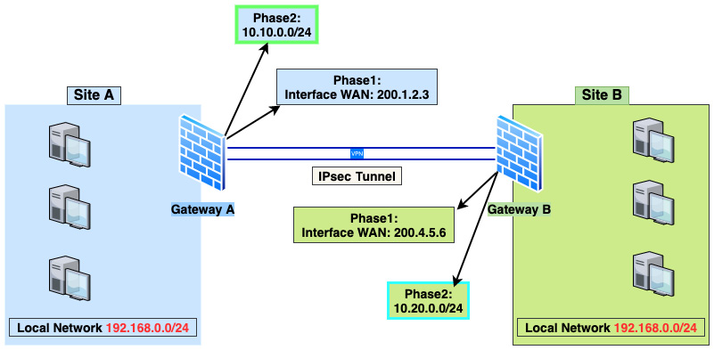
Figure 8.5 – IPSec BINAT example
As shown in the preceding diagram, both Site A and Site B have the same local network address, 192.168.0.0/24, which is a problem while connecting both sites using an IPsec tunnel. How could we fix this issue and connect these networks without changing the network address on one of the sites? The short answer is we can apply a NAT rule before packets enter the tunnel. Let's see how to do that.
To achieve our goal, we first need to define two new network addresses that don't exist on both sides. In our example, these are as follows:
- Site A: 10.10.0.0/24
- Site B: 10.20.0.0/24
These two new network addresses will be only used in Phase 2 and NAT configuration. Let's go through the steps needed to make it happen.
Note
Let's assume here we are doing all the steps on Site A.
Let's move on to create our first NAT rule.
Creating a NAT one-to-one rule
To masquerade the traffic from the local network to the IPsec tunnel, we need to create a one-to-one NAT rule.
To create a new NAT one-to-one rule, go to Firewall | NAT | One-to-One and click on the + button. Fill the new rule with the following options:
- Interface: IPsec.
- Type: BINAT.
- External network: 10.10.0.0/24.
- Source: Single host or Network – 192.168.0.0/24.
- Destination: Single host or Network – 10.20.0.0/24.
- Description: IPSec BINAT example.
- Click on the Save button.
After that, the new rule is created as shown in the following screenshot:

Figure 8.6 – NAT one-to-one BINAT example rule
As we can see in the preceding screenshot, the new network is configured as External IP while the actual network address is Internal IP. Now let's take steps to add the configuration on the IPSec tunnel.
Creating a new IPSec tunnel
Next, we'll create an IPsec tunnel to work with the previously created BINAT rule through the following steps:
- Go back to VPN | IPSec | Tunnel Settings to create new Phase 1 and Phase 2 configurations.
- Add a new Phase 1 configuration. I will provide some example configuration options, but you can change or adapt to your lab or network environment settings (leave the not mentioned options with default values or empty):
- Connection method: default.
- Key Exchange version: auto.
- Internet Protocol: IPv4.
- Interface: WAN.
- Remote gateway: Type the Site B/other firewall's IP address.
- Description: Site A Phase 1 configuration.
- Authentication method: Mutual PSK.
- My identifier: My IP address.
- Peer identifier: Peer IP address.
- Pre-Shared Key: Create a strong PSK here.
- Encryption algorithm: AES 256.
- Hash algorithm: SHA 256.
- DH key group: 14 (2048 bits).
- Lifetime: 28800.
- Install policy: Checked.
- To finish, click on the Save button.
- Add a new Phase 2 configuration (leave the not mentioned options with default values or empty):
- Mode Tunnel: Tunnel IPv4
- Description: Site A Network
- Local Network:
- Type: Network
- Address: 10.10.0.0/24
- Remote Network:
- Type: Network
- Address: 10.20.0.0/24
- Protocol: ESP
- Encryption algorithms: AES auto
- Hash algorithms: SHA256
- Lifetime: 3600
- Manual SPD entries: 192.168.0.0/24
Note
The Manual SPD entries option ensures that the previously created NAT rule works with the IPsec tunnel.
- Click on the Save button to finish adding this Phase 2 configuration.
After creating both phases, the new IPSec configuration should look as follows:

Figure 8.7 – IPsec example configuration
The preceding screenshot shows the Site A configuration. To create the Site B configuration, repeat the preceding steps, swapping the networks and gateway-related options on firewall B to get it working.
As you can see, OPNsense has powerful features to help with tricky scenarios such as in the preceding example. To finish our IPsec site-to-site expedition, let's look at the routed IPsec tunnel.
IPsec routed tunnel (VTI)
The routed tunnel configuration uses a Virtual Tunnel Interface (VTI), so you will probably hear people calling this IPsec configuration just VTI. The main difference with this kind of configuration is that instead of using a policy based on routes managed by the IPsec daemon and the kernel, it will use installed routes on the operating system using the virtual interface. If you already use OpenVPN tunnels, it will sound familiar to you; the working principle is almost the same.
Following the steps from the IPsec BINAT example, you can alter a few steps to change it from a policy-based to a route-based tunnel. You don't need to follow the NAT rule steps and change the network address to the existing local networks configured in Site A and B firewalls.
Let's go through the steps:
- Follow the steps for Phase 1 as discussed in the Creating a new IPSec tunnel section, leaving the following options unchecked:
- Install policy
- Disable Rekey
- Disable Reauth
- Dead Peer Detection
- Disable NAT Traversal: NAT Traversal: Disabled
- In Phase 2, we must create a tunnel IP for each tunnel side instead of defining the local network as we did before while configuring a policy-based tunnel. Follow the steps and change the following options (assuming Site A as an example):
- Local Network:
- Type: Address
- Address: 10.254.1.1
- Remote Network
- Type: Network
- Address: 10.254.1.2
- Local Network:
Leave the Manual SPD entries option empty.
- Go to System | Gateways | Single and create a new gateway:
Click on the Save button to add the new IPsec gateway.
- Go to System | Routes | Configuration to add the tunnel route.
Click on the + button and fill in the options as follows:
- Network Address: Site B's network (for example, 192.168.1.0/24)
- Gateway: IPSecGW
- Description: IPSec Site B route
Click on the Save button to finish adding the new route. Congratulations! You just set your new IPSec routed tunnel!
Now that we have explored IPSec site-to-site configurations, let's look at some diagnostics tools that we can use while checking everything is OK with our tunnels.
IPSec diagnostics
Sometimes IPSec issues can be tricky, but OPNsense has some helpful diagnostic resources to help to identify and solve IPSec issues. If you need to check whether a tunnel is up and running, go to VPN | IPsec | Status Overview:

Figure 8.8 – A running IPsec tunnel status
As shown in the screenshot, you can check that Phase 1 is up (green play icon). To check Phase 2, you must click on the i button, and the defined local subnets will be shown with some extra information such as statistics, state, and remote subnets.
To check log files on the webGUI, go to VPN | IPsec | Log file. On this page, you can check all logs generated by the IPsec daemon. You can also check the log file using the CLI:
#tail -f /var/log/ipsec.log
To list all current IKE SAs, you can go to VPN | IPsec | Security Association Database.
To list the SPD, check VPN | IPsec | Security Policy Database.
To manage the IPsec daemon on the CLI, use the ipsec command. Some examples of its usage are the following:
To list routed connections and security associations, use the following command:
#ipsec status
If you want to see a specific tunnel output, add the connection name (con, for example) and use the following command:
#ipsec status con1
To list the daemon's listening IP addresses, connections, routed connections, and security associations, use the following command:
#ipsec statusall
To list all the available options, type the following:
#ipsec --help
As you may notice, the IPsec topic has content that could fill an entire book, so I tried to cover the most relevant subjects related to it in this chapter. As mentioned earlier in this chapter, I recommend you take a look at the official OPNsense documentation to explore other IPsec topics: https://docs.opnsense.org/manual/vpnet.html#ipsec.
Firewall rules
Finally, remember to create all the firewall rules to allow traffic to pass through each firewall. In the previous examples, we'll need to add rules on local networks and IPsec interfaces. The official OPNsense documentation recommends creating rules on WAN interfaces to allow ESP, ISAKMP, and NAT-T traffic. Still, I have seen many OPNsense firewalls without those rules, working with IPsec tunnels. So why should you create those rules? First, it's good practice! Another reason is that with OPNsense's evolution, this behavior can change in the future, and your tunnels could stop working after an update. You can check the rules out here: https://docs.opnsense.org/manual/how-tos/ipsec-s2s.html#firewall-rules-site-a-site-b-part-1.
Now let's move on with OpenVPN and see how to employ it in different VPN deployments.
VPN deployments using OpenVPN
As discussed previously, OpenVPN is a versatile VPN protocol and works well both in site-to-site and remote user deployments. Let's assume a similar scenario to the one we used in the IPsec site-to-site topic as an example to start this section.
Site-to-site deployment
In the following topology, you will notice that the tunnel network has a 10.10.10.0/30 address with just two usable addresses, one to each firewall:

Figure 8.9 – OpenVPN site-to-site topology example
We will configure this tunnel using a shared key to stay on the same track as our previous IPsec example. OpenVPN supports authentication using certificates for site-to-site deployments, although this chapter will look at it later, in the remote user deployment topic.
OpenVPN uses a client-server approach, so to define which side of the tunnel should be set as a server or client, you should take these things into consideration:
- MultiWAN OPNsense as OpenVPN client: Sometimes, a site is set as a client even if it is the only one with the multi-WAN configuration. The reason? A well-configured multi-WAN OPNsense firewall will switch the default gateway quickly if a WAN link goes down. Otherwise, if it is set as the server on the OpenVPN deployment, changing from one downlink to another online can take longer once the client side waits for a timeout before reconnecting to another configured WAN link.
- Dynamic IP firewall/NATed IP address: In this case, you'll probably want to set this firewall as the OpenVPN client, especially if the other firewall has a static public IP configured. The client side needs to find the server to bring the tunnel up, hence, it is better to have the client side using a dynamic or NATed IP address; otherwise, setting the tunnel wouldn't be possible.
Considerations made, let's see how to configure a site-to-site tunnel using OpenVPN:
- Go to VPN | OpenVPN | Servers.
- Click on the + icon to create a new OpenVPN server.
A new page will open with the following options. Please refer to the preceding example topology to fill in these options:
- General information: This section refers to general tunnel information.
- Disabled: Leave this unchecked to enable this server.
- Description: Fill it with something that describes this server.
- Server Mode: This option will set which operation mode the server will be configured in. The following are the operation modes:
- Peer to Peer (SSL/TLS): Choose to set a site-to-site tunnel using a certificate as the authentication method.
- Peer to Peer (Shared Key): Choose to set a site-to-site tunnel using a shared key string. We'll select this for our example.
- Remote Access (SSL/TLS): This option is used for remote user tunnels using a certificate as the authentication method.
- Remote Access (User Auth): When selected, this will configure a remote user tunnel using only a username and password as the authentication method.
- Remote Access (SSL/TLS + User Auth): Sets a remote user tunnel utilizing a combination of both previous options, that is, certificate and username/password authentication. It is the safer option for remote user tunnels but isn't easy to configure while using an external authentication backend such as RADIUS or LDAP (Active Directory, for example).
- Protocol: The available options are UDP4, TCP4 for IPv4 and UDP6, or TCP6 for IPv6. To use both IP versions, select one of the UDP or TCP options. For our example, we'll choose UDP. Using TCP could impact the tunnel's throughput performance.
- Device Mode: Then, you can choose which operation mode the virtual network will use:
- tun: Select for a route-based tunnel. Select this one.
- tap: Select for both a route-based and a capable bridge tunnel (layer 2).
- Interface: Select which interface OpenVPN will listen to for connections. To enable all, select any. Leave the default option: any.
- Local port: Choose which port the server will listen to for incoming connections. Leave the default 1194.
- Cryptographic Setting: All related cryptographic settings will be set in this section, some of which are discussed here:
- Shared Key: Check Automatically generate a shared key to generate a shared key, or uncheck this option to paste a shared key if you already have one. Leave the default: checked.
- Encryption algorithm: Select which encryption algorithm you want to use. For our example, select AES-256-CBC.
- Auth Digest Algorithm: Select which authentication digest algorithm to use in this tunnel. For our example, select SHA 256.
- Tunnel Settings: In this section, the tunnel's networks and routes will be configured:
- IPv4 Tunnel Network: Defines the tunnel's virtual network for the peer-to-peer connection. We will fill it with 10.10.10.0/30.
- IPv6 Tunnel Network: Define the network, if you want to set the tunnel's virtual network using IPv6.
- Redirect Gateway: Check this option to force all clients' traffic to be routed to the tunnel. Use it with caution!
- IPv4 Local Network: Defines which networks will be routed through the tunnel. You can add more than one network, filling in the addresses separated by a comma. For our example, fill it with 192.168.0.0/24.
- IPv6 Local Network: The same as the previous option, but using IPv6 networks instead.
- IPv4 Remote Network: Defines which remote networks will be reachable through the tunnel. You can add more than one network by filling in the addresses separated by a comma. For our example, fill it with 192.168.1.0/24.
- IPv6 Remote Network: The same as the previous option, but using IPv6 networks.
- Concurrent connections: Defines the maximum number of concurrent clients connected in this tunnel.
- Compression: Defines which compression algorithm will be used in this tunnel. Leave No preference for no compression.
- Type-of-Service: Check this option to enable TOS on traffic going through the tunnel. This may be desirable while using VoIP traffic inside the tunnel.
Note
Using the Type-of-Service option can leak information about the traffic.
- Duplicate Connections: If this option is checked, the OpenVPN server will allow clients to connect with the same Common Name (CN). It is not recommended!
- Disable IPv6: Checking this option means it doesn't send IPv6 through the tunnel.
- Client Settings: This section will define client-related options.
- Dynamic IP: Check this option for better stability for roaming users with frequent IP address changes.
- Address Pool: This option will automatically set the IP addresses pool to be leased to clients. In our example, you can uncheck it.
- Topology: If checked, this will assign one IP instead of a /30 subnet per connected client. Using a topology can save IP addresses from the tunnel network pool once all usable addresses from the subnet have been allocated. According to the OpenVPN official documentation, Windows clients with old OpenVPN versions (before 2.0.9) will not work with the Topology option enabled, so take care before enabling it.
- Client Management Port: Select this option to change the default client's management port (166).
- Advanced configuration: From this point forward, you must go with caution. Advanced options, when set without proper knowledge, can break things!
- Advanced: You can set OpenVPN server-compatible options separated by a semicolon (;). Everything you type here will be written on the server's configuration file. Caution!
- Verbosity level: Select which log verbosity level you want to set. The levels are as follows (extracted from the OPNsense webGUI):
- 0: No output except fatal errors.
- 1: Startup information, connection-initiated messages, and non-fatal encryption and network errors.
- 2 and 3: Show TLS negotiations and route information.
- 4: Normal usage range.
- 5: Output R and W characters to the console for each packet read and write. Uppercase is used for TCP/UDP packets and lowercase is used for TUN/TAP packets.
- 6-11: Debug information range.
- Force CSO Login Matching: Client-Specific Overrides (CSO) is a way to set custom configurations to clients based on CN. To use the username to match a client instead of CN, check this option.
- To add the new OpenVPN server configuration, click on the Save button.
After creating the Site A OpenVPN server, we'll need to set the Site B OpenVPN client:
- On the Site B firewall, go to VPN | OpenVPN | Clients and add a new client configuration, clicking on the + button.
- Configure the options as follows (leave not mentioned options as the default):
- Server Mode: Peer to Peer (Shared Key)
- Protocol: UDP
- Device mode: tun
- Interface: any
Remote server:
- Host or address: Fill with the OpenVPN server address (probably the WAN interface address).
- Port: Fill with the configured server's port (1194 in our example).
- In Cryptographic Settings, uncheck the Shared Key option Automatically generate a shared key, go back to the OpenVPN server settings, and copy/paste the shared key here. In the other options, select the same configuration as the server.
- In Tunnel Settings, fill IPv4 Tunnel Network with 10.10.10.0/30, and fill IPv4 Remote Network with the Site A local network address: 192.168.0.0/24.
- Click on the Save button to add the new OpenVPN client configuration.
Note
OPNsense must have a firewall rule on the WAN interface permitting traffic on UDP port 1194 to allow connections on the new OpenVPN tunnel on the server side.
- To check whether the new OpenVPN tunnel is up, go to VPN | OpenVPN | Connection Status.
- You will see something like the following:
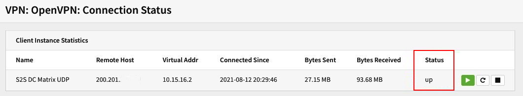
Figure 8.10 – OpenVPN Connection Status page
In the preceding screenshot, we can see the status on the OpenVPN client side with the tunnel up. If you did everything right, you should see the tunnel up on both sides of your OPNsense firewalls.
Remote user deployment
The remote user deployment is often used to provide secure access for remote employees and their companies. In this topic, we'll explore an example connecting remote users to a company's local network using user authentication. Let's go through the steps to set up our remote user deployments.
The following topology shows a typical client-to-site OpenVPN scenario, in which each user can have their own rules and routes controlled by the OPNsense firewall. We'll go through the steps to configure an OpenVPN tunnel based on the screenshot in Figure 8.10.

Figure 8.11 – OpenVPN remote users topology example
The first step is to create a Certificate Authority (CA) that will be used in an OpenVPN tunnel configuration. We'll need it to create a certificate later. To start, go to System | Trust | Authorities and click on the + button.
Fill in the options as follows:
- Descriptive name: OpenVPN CA.
- Method: Select Create an internal Certificate Authority.
- Key Type: Select RSA.
- Key length (bits): Select 4096.
- Digest Algorithm: Select SHA512.
- Lifetime (days): You can leave the default value as 825.
Note
It is recommended to create a CA with a longer lifetime. Otherwise, you would have to exchange all VPN connections that rely on certificates based on it.
- Country Code: Select your country; in this example, we'll choose Portugal.
- State or Province: Fill with yours; for the example, we'll use Lisboa.
- City: Fill with yours; for the example, we'll use Lisboa.
- Organization: Fill with yours; for the example, we'll use Cloudfence.
- Email Address: Fill with your company department or server administrator address; for the example, we'll use [email protected].
- Common Name: internal-openvpn-ca.
- To finish creating the CA click on the Save button.
Next, we need to create the certificate that we'll also use in our OpenVPN tunnel configuration. It will be required to sign the client certificates. Follow the given steps:
- To create the certificate, go to System | Trust | Certificates and click on the + button.
Use the following points to guide you through creating a certificate, which will be required to set up your OpenVPN tunnel:
- Method: Select Create an internal Certificate.
- Descriptive name: OpenVPN certificate.
- In the Internal Certificate section, set the options as follows:
- Certificate authority: Select the previously created CA.
- Type: Select Server certificate.
- Key Type: Select RSA.
- Key length (bits): Select 4096.
- Digest Algorithm: Select SHA512.
- Private key location: Save on this firewall.
- In the Distinguished name section, set the options as follows:
- Country Code: Select your country; in this example, we'll choose Portugal.
- State or Province: Fill with yours; for the example, we'll use Lisboa.
- City: Fill with yours; for the example, we'll use Lisboa.
- Organization: Fill with yours; for the example, we'll use Cloudfence.
- Email Address: Fill with yours; for the example, we'll use [email protected].
- Common Name: OpenVPN server certificate.
- To finish creating the certificate, click on the Save button.
The following are the steps for creating the OpenVPN server:
- Go to VPN | OpenVPN | Servers and click on the + button. Set the options as described in the following. (Options that are not mentioned here can be left as the default.)
On the General information page, set the options as follows:
- Description: For example, Remote users server.
- Server Mode: Select Remote Access (SSL/TLS + User Auth).
- Backend for authentication: Select Local Database.
- Protocol: Select UDP.
- Device Mode: Select tun.
- Interface: Select any.
- Local port: Leave the default value; for this example, it is 1195.
- Next, we'll define the cryptographic settings:
- TLS Authentication: Both options must be checked – Enable authentication of TLS packets and Automatically generate a shared TLS authentication key.
- Peer Certificate Authority: Select the CA we created before.
- Server Certificate: Select the server certificate we created before.
- DH Parameters Length: Select 4096 bit.
- Encryption algorithm: Select AES-256-CBC.
- Auth Digest Algorithm: Select SHA512.
- Certificate Depth: Select One (Client+Server).
- IPv4 Tunnel Network: 10.10.10.0/24.
- Disable IPv6: Check this option.
- To finish the OpenVPN server creation, click on the Save button.
- Now, we need to create the users to connect to this OpenVPN server. Go to System | Access | Users and click on the + button to create a user.
- Fill in the Username and Password fields, check the Certificate option Click to create a user certificate, and click on the Save and go back button to add the user.
- A new page will open to create the user's certificate. Change the Method option to Create an internal Certificate and check whether the CA we have created is selected. It might be selected by default; if not, do it.
- Click on the Save button to create the user's certificate.
Note
OPNsense must have a firewall rule on the interface that will receive the OpenVPN connections permitting traffic on UDP port 1195 (set in Local Port) to allow connections to the newly created OpenVPN tunnel on the server side.
- To test our tunnel, you will need to export the client configuration. To do that, go to VPN | OpenVPN | Client Export.
- Remote Access Server: Select the tunnel you have created.
- Export type: Depending on the client's operating system and OpenVPN client version, you can choose the right option. For example, on a Windows-based client, you can select the File Only or Archive option.
- Hostname: Type in your firewall's WAN address or an FQDN hostname (published on the internet).
- Port: Use the port of the OpenVPN server; in our example, it is 1195. You can set some extra options, including custom options, in the Custom config field. For this example, we'll use the default configuration. To download the user config file, click on the download button as shown in the following screenshot:

Figure 8.12 – Exporting OpenVPN client configuration
- Create a firewall rule on the OpenVPN server permitting all the traffic for testing purposes.
- After downloading the client's configuration, you can connect to the newly created OpenVPN tunnel using your favorite client:
- Windows: https://openvpn.net/community-downloads/
- macOS: https://tunnelblick.net/downloads.html
- Linux: Most distributions have the OpenVPN package as default. You will be able to install it without significant problems. Some Linux distributions allow you to configure using the network manager, which will ease the usage a lot. For example, after a connection is made to a hotel WLAN, autostart the VPN.
- Android and iOS: Search on Google Play and App Store for OpenVPN, and you'll find the client for your favorite mobile platform.
- To configure each OpenVPN client, I suggest you consult the official documentation of the client you'll use. The OPNsense official documentation has some guides for each platform as a starting point: https://docs.opnsense.org/manual/how-tos/sslvpn_client.html#step-3-export-client-configuration.
- Once you have downloaded the OpenVPN client and imported the configuration, you can try connecting to your new OpenVPN server. Once you do so from VPN | OpenVPN | Connection Status, your client's connection will look like this:
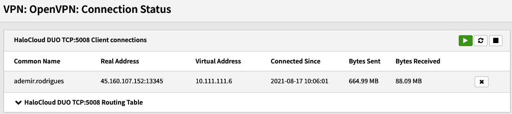
Figure 8.13 – OpenVPN connected user example
If you can see something like the preceding screenshot on your OPNsense firewall, congratulations! Your remote user connection is working! If it isn't working yet, repeat the steps you took to configure and check your OpenVPN client logs to try to find a clue. If you already did that and it is still not working, try the following topic.
OpenVPN diagnostics
For both site-to-site and remote user scenarios, when things are not working as expected, we can try using some valuable tools offered by OPNsense to find possible issues. Let's look at some examples.
OpenVPN is connected but the traffic is not reaching the tunnel's destinations
I have tried to list the more common issues related to OpenVPN troubleshooting based on my personal experience here:
- The first step is to check your firewall rules and look for packets that have been blocked. Especially check the OpenVPN firewall rules and check all necessary rules have been created.
- On the client side, it can happen that the operating system is not creating the proper routes. This issue can be related to the user's permissions or some local network problem while creating the tunnel routes. Another common cause is conflicting routes (with existing interfaces or even with an IPsec tunnel).
- Always check the log file on both sides (server and client). On OPNsense, you can check logs by accessing the VPN | OpenVPN | Log file menu, or on the CLI by reading the openvpn.log file:
#tail -f /var/log/openvpn.log
This is a short list, but you might face issues that will have a mix of them. You can also explore the OPNsense forum to get some more help when you need it.
OpenVPN client is not connecting to the server/a site-to-site tunnel doesn't become up
This might be related to firewall rules on the configured tunnel interface (the Interface option) or even a wrong interface selected in this option.
A single user cannot connect
Most user connection issues are related to the operating system configuration or user privileges, so it is good to start looking at the user's computer for the following:
- In this case, a common issue is when some users forget or use the wrong credentials. The best place to look is in the OpenVPN log file. It can happen too when there is a problem with the user's connection or OpenVPN client. A good alternative is to ask the user to change the internet connection (from Wi-Fi to a cable or cellular network). On Windows hosts, reinstalling the OpenVPN client sometimes can help.
- For all situations, always keep your eye on the logs; they can help a lot!
- The tunnel connection port might be blocked in the user network (for example, hotels, airports, and other guest networks).
Unfortunately, we cannot list all the issues related to OpenVPN here. Still, you can always count on OPNsense's community, especially on the forum, to understand what could be happening with your OpenVPN issues.
Summary
In this chapter, you have learned about Quality of Service (QoS) and traffic shaping basics, how to create pipes, queues, and rules in the OPNsense webGUI, and how to test them. Now you can design a traffic shaping policy based on the network requirements and create rules to apply it using OPNsense features. In the next chapter, we will begin our exploration of the VPN world.
In this chapter, we learned about IPsec and OpenVPN, the pros and cons of each one, how to employ IPsec and OpenVPN to connect remote networks using a site-to-site approach, and how to use OpenVPN to connect remote users. We have explored the diagnostics tools OPNsense provides and some common issues you can face while using them. In the next chapter, we will learn about OPNsense's multi-WAN capabilities.