
Chapter 3: Configuring an OPNsense Network
In this chapter, we will learn more about some hardware considerations concerning networking and how to configure a network interface using the OPNsense WebGUI, and we will explore the network interface types available to configure in it. We will also learn about the virtual IPs and the differences between them, and finally we will look at some common troubleshooting scenarios and how to solve issues using the diagnostics tools available in OPNsense.
In this chapter, we will cover the following topics:
- Hardware considerations
- Configuring a basic network
- Types of network interfaces
- Exploring virtual IPs
- Networking diagnostics and troubleshooting
Technical requirements
This chapter requires that you have a clear understanding of the TCP/IP network stack, OSI model concepts, and some experience of using a command shell, or CLI. You will need a running OPNsense to practice some of the exercises proposed in this chapter. If you have followed all the steps from the previous chapters of this book, you can use your newly configured OPNsense virtual machine.
Hardware considerations
It is crucial to choose the right hardware for your OPNsense, so that it functions well as a firewall, and the most important components are the CPU and the network interface cards (NICs). For example, choosing the right NIC for the network environment can make the difference between a successful deployment and a complete disaster. Of course, the high-quality code of OPNsense can do an outstanding job while securing networks, but without a good hardware bundle, it won't make any magic.
As we discussed in the last chapter, the kernel OPNsense runs on has the netmap framework implemented in it, which can be used by network IPS and Sunny Valley's Sensei plugin, for example, to process network packets with better performance and low CPU usage. If one of your OPNsense installation tasks uses one or maybe both of these (network IPS and Sensei plugin in different NICs), then you should choose a network card with a driver that is supported by netmap to get the job done; otherwise, the whole system will suffer from high CPU load when processing network packets while using these components.
Before starting your OPNsense firewall implementation, let's take into account the following considerations:
- Network size and overall throughput: Is it expected to have a lot of concurrent connections being processed by OPNsense? Consider that every new connection state will consume 1 KB of RAM; for example, if you need 1,000,000 concurrent connections, 1 GB of the firewall's RAM will be consumed.
- Features that may demand more hardware power: As an example, we can talk about a web proxy with HTTPS inspection or an Intrusion Detection System/ Intrusion Prevention System (IDS/IPS) enabled that consumes a lot of CPU and RAM resources. Another example is if you have a lot of VPN tunnels; maybe you could consider a CPU with Advanced Encryption Standards-New Instructions (AES-NI) support, which is an instruction set that some CPUs have to improve performance while using some algorithms using the Advanced Encryption Standard (AES). Using this algorithm will mean better performance.
- The number of services that will be running in the firewall: If you are considering building a firewall with a lot of services running on it, for example, a proxy server, a VPN, an IDS/IPS, and a firewall, and you install a bunch of plugins to do other tasks, then aside from a good CPU and network card, consider using a lot of RAM too.
These are some examples of possibilities you may consider in your OPNsense deployment. It is not within the book's scope to give you basic recipes on how to deploy each one; however, I will show you the right path to know what to look for before building your OPNsense firewall.
FreeBSD NIC names
FreeBSD uses the network interface driver to name each installed card followed by a number, starting at 0. For example, if you install two Intel PRO/1000 network cards, they will be identified as igb0 and igb1; the igb part is from the driver used by FreeBSD to manage this type of Intel Gigabit network card, followed by the number to identify each one: in this example, 0 for the first network card and 1 for the second one.
Here is a reference: https://docs.freebsd.org/doc/7.3-RELEASE/usr/share/doc/en/articles/linux-users/network.html.
The ifconfig command
The ifconfig command is a native FreeBSD network tool that can help you in managing network interfaces in the CLI. This tool can be considered as the Swiss army knife of network managing tools in CLI.
Important Note
Changes made using the ifconfig command will not survive a reboot!
In the CLI, an easy way to list the installed network interfaces is using the ifconfig command:
root@bluebox:~ # ifconfig
igb0: flags=8943<UP,BROADCAST,RUNNING,PROMISC,SIMPLEX,MULTICAST> metric 0 mtu 1500
options=8500b8<VLAN_MTU,VLAN_HWTAGGING,JUMBO_MTU,VLAN_HWCSUM,VLAN_HWFILTER,VLAN_HWTSO>
ether 00:90:0b:4d:25:b0
inet6 fe80::290:bff:fe4d:25b0%igb0 prefixlen 64 scopeid 0x1
groups: LAN
media: Ethernet autoselect (1000baseT <full-duplex>)
status: active
nd6 options=21<PERFORMNUD,AUTO_LINKLOCAL>
igb1: flags=8843<UP,BROADCAST,RUNNING,SIMPLEX,MULTICAST> metric 0 mtu 1500
options=8500b8<VLAN_MTU,VLAN_HWTAGGING,JUMBO_MTU,VLAN_HWCSUM,VLAN_HWFILTER,VLAN_HWTSO>
ether 00:90:0b:4d:25:b1
inet6 fe80::290:bff:fe4d:25b1%igb1 prefixlen 64 scopeid 0x2
inet 192.168.15.9 netmask 0xffffff00 broadcast 192.168.15.255
media: Ethernet autoselect (100baseTX <full-duplex>)
status: active
nd6 options=21<PERFORMNUD,AUTO_LINKLOCAL>
To list a specific network interface, just type ifconfig followed by the interface name:
root@bluebox:~ # ifconfig igb1
igb1: flags=8843<UP,BROADCAST,RUNNING,SIMPLEX,MULTICAST> metric 0 mtu 1500
options=8500b8<VLAN_MTU,VLAN_HWTAGGING,JUMBO_MTU,VLAN_HWCSUM,VLAN_HWFILTER,VLAN_HWTSO>
ether 00:90:0b:4d:25:b1
inet6 fe80::290:bff:fe4d:25b1%igb1 prefixlen 64 scopeid 0x2
inet 192.168.15.9 netmask 0xffffff00 broadcast 192.168.15.255
media: Ethernet autoselect (100baseTX <full-duplex>)
status: active
nd6 options=21<PERFORMNUD,AUTO_LINKLOCAL>
In the preceding example, you selected the igb1 network interface, and as we can see, the IPv4-configured IP address is 192.168.15.9 with a 24-bit netmask (0xffffff00) and a network broadcast address of 192.168.15.255. But wait a moment! A 24-bit netmask? Where?! Don't worry! Let's understand this part. If you came from the Linux world, like me, you are probably wondering why on earth this netmask is in hexadecimal format.
Well, the default option in the ifconfig command in FreeBSD is hex notation, but we can change that with some parameters, but before we change it in ifconfig, let's remember some concepts.
If you convert the value 0xffffff00 to binary notation, you will get the following:
11111111 11111111 11111111 00000000
Counting the 1 bit, you have 24 bits, right? Remembering the network basic classes, the IPv4 address has 4 octets. Converting that to decimal, we get the following:
- 1st octet: 8 bits in 1 state = 255 decimal
- 2nd octet: 8 bits in 1 state = 255 decimal
- 3rd octet: 8 bits in 1 state = 255 decimal
- 4th octet: 8 bits in 0 state = 0 decimal
This equals 255.255.255.0 decimal.
Important Note
This chapter requires that you have a basic IPv4 understanding: how to convert hex numbers to binary and decimal will not be detailed here. If you don't know how exactly to do that, I strongly recommend you read some Packt books about network basics before moving on with firewalling. It's just advice, but you can always make use of calculators to convert these numbers too.
Now that we have remembered some of the basics of IPv4 concepts, we can try to convert a hex to a decimal using ifconfig:
root@bluebox:~ # ifconfig -f inet:dotted igb1
igb1: flags=8843<UP,BROADCAST,RUNNING,SIMPLEX,MULTICAST> metric 0 mtu 1500
options=8500b8<VLAN_MTU,VLAN_HWTAGGING,JUMBO_MTU,VLAN_HWCSUM,VLAN_HWFILTER,VLAN_HWTSO>
ether 00:90:0b:4d:25:b1
inet6 fe80::290:bff:fe4d:25b1%igb1 prefixlen 64 scopeid 0x2
inet 192.168.15.9 netmask 255.255.255.0 broadcast 192.168.15.255
media: Ethernet autoselect (100baseTX <full-duplex>)
status: active
nd6 options=21<PERFORMNUD,AUTO_LINKLOCAL>
Adding the -f inet:dotted parameter to the ifconfig command, now we can see the netmask in decimal notation: 255.255.255.0.
Better? But you want more? OK! Let's try now with CIDR notation. For that, just change the ifconfig parameter to -f inet:cidr:
root@bluebox:~ # ifconfig -f inet:cidr igb1
igb1: flags=8843<UP,BROADCAST,RUNNING,SIMPLEX,MULTICAST> metric 0 mtu 1500
options=8500b8<VLAN_MTU,VLAN_HWTAGGING,JUMBO_MTU,VLAN_HWCSUM,VLAN_HWFILTER,VLAN_HWTSO>
ether 00:90:0b:4d:25:b1
inet6 fe80::290:bff:fe4d:25b1%igb1 prefixlen 64 scopeid 0x2
inet 192.168.15.9/24 broadcast 192.168.15.255
media: Ethernet autoselect (100baseTX <full-duplex>)
status: active
nd6 options=21<PERFORMNUD,AUTO_LINKLOCAL>
Now we can see the IP address followed by CIDR notation:
inet 192.168.15.9/24 broadcast 192.168.15.255
Here are some other important parts of the output of the ifconfig command as regards hardware:
- ether 00:90:0b:4d:25:b1: Here, ether shows the physical address of the NIC, also known as the MAC address.
- options=8500b8<VLAN_MTU,VLAN_HWTAGGING,JUMBO_MTU,VLAN_HWCSUM,VLAN_HWFILTER,VLAN_HWTSO>: Here, we can check which options are supported by the network interface driver. In this example, we have options such as VLAN hardware tagging support (VLAN_HWTAGGING) and jumbo frames (JUMBO_MTU), which is the support required for a maximum transmission unit (MTU) with more than 1,500 bytes, and some other options available to this NIC. The available options may vary depending on the selected network card.
- media: Ethernet autoselect (100baseTX <full-duplex>): Here, media shows the active media type used to connect the NIC physically to the network; for example, 100baseTX is a twisted-pair cable that supports 100 Mbps.
- status: active: Here, status shows that this NIC is active, in this example, with the cable connected.
Want to learn more about the ifconfig command? Take a look at FreeBSD's ifconfig man page: https://www.freebsd.org/cgi/man.cgi?ifconfig(8).
Now that we have explored the NIC considerations and learned how to get some information about the NIC in the CLI, we can move on to configuring a basic network in OPNsense.
Basic network configuration
Local network configuration begins with a good IP addressing plan! Always try to follow the RFC1918 reserved address space (10.0.0.0/8, 172.16.0.0/12, and 192.168.0.0/16) for local networks, using private IP addresses. In this way, you avoid future issues with local addresses overlapping with public addresses on the internet. I have seen many times network administrators not paying attention to this rule of thumb and creating problems for themselves.
Another good practice is not using huge broadcast domains. If you are projecting a small network, then why use a 10.0.0.0/8 network? Avoid doing that! This can save you time in the future; for example, while connecting two or more networks using a VPN tunnel, there will be a smaller chance of network addresses overlapping with other connected networks. If you choose 10.10.10.0/24, which means 254 usable IP addresses, instead of choosing 10.0.0.0/8, which has more than 16 million IP addresses, which one do you think has more chances of conflict with another 10.x.x.x address networks? Smaller broadcast domains means smaller chances of conflicts happening.
Some good tools to start your firewall and network project are a piece of paper and a pencil. Draw your network plan and discuss it with your work buddies before starting to set IP addresses for network devices.
After these brief considerations, let's go to the network configuration.
WebGUI – network interface configuration
Everything that we need to configure a network interface is in the Interfaces menu. OPNsense will set the LAN and WAN interfaces by default, as we explored in Chapter 2, Installing OPNsense, where we already configured both, so let's explore the available network configuration options in WebGUI.
The following options are available both in LAN and WAN interface configuration or in any new network interface you may add later in your OPNsense.
To explore the network interface configuration options, head to the Interfaces | LAN menu (you can also try Interfaces | WAN; the options are the same):
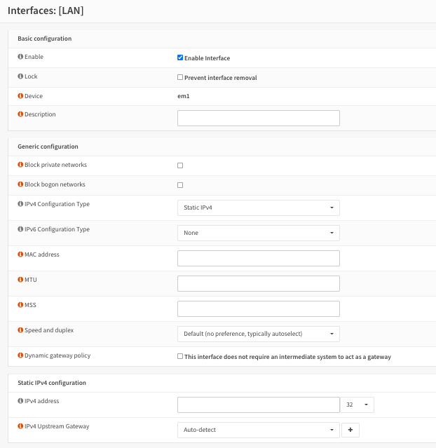
Figure 3.1 – Network interface configuration options
The available basic configuration options are as follows:
- Enable Interface: When checked, this will enable the network interface.
- Lock: This will prevent the network interface being removed. This option can protect against accidental removal.
- Device: Just a label showing the name of the FreeBSD network interface.
- Description: Here, you can set an interface name that will be used in WebGUI.
Here are the generic configuration options:
- Block private networks: When checked, this will block all traffic from the RFC1918 private network space as well as the loopback reserved address (127.0.0.0/8) and carrier-grade NAT addresses (100.64.0.0/10). Don't use it in local network interfaces! You may check this option in WAN interfaces.
- Block bogon networks: When checked, this will block reserved addresses (not yet assigned by IANA), which does not include RFC1918. You may check this option in WAN interfaces.
- IPv4 Configuration Type:
- None: This will not assign any IP address to the interface.
- Static IPv4: This will set a static IP address to the interface.
- DHCP: This will use the DHCP protocol to set a network interface IP address.
- PPP: This will set this network interface using the PPP protocol; common usage is connecting using a mobile networking modem.
- PPPoE: This will configure this network interface using the PPP over the Ethernet protocol; common usage is connecting through DSL networks.
- PPTP / L2TP: This will use the PPTP or L2TP protocol to set up a connection in the interface; both will require the same configuration options, such as username and password, for example.
- IPv6 Configuration Type:
- Static IPv6: This will set a static IPv6 address to the interface.
- DHCPv6: This will use the DHCPv6 protocol to set a network interface IPv6 address.
- SLAAC: This will configure an interface using stateless address autoconfiguration.
- 6rd Tunnel: This will set the interface using IPv6 rapid deployment. This configuration will probably be served by your ISP.
- 6to4 Tunnel: This will set the interface using tunneling IPv6 inside an IPv4 mechanism.
- Track interface: This will track configuration from another interface configured using IPv6.
- MAC address: Use this to spoof the interface physical address; it will be set in the network interface. A common usage of it is when you have to change a network card or the entire OPNsense hardware without changing the MAC address from the old hardware. Take care when using this option!
- MTU: This will set the MTU in the interface; the default value for Ethernet is 1,500 bytes.
- MSS: This option changes the maximum segment size for TCP connections to be used by the interface.
- Speed and duplex: Keeping this as the default option, Default (no preference, typically autoselect), will mean auto-negotiating between the network card and the switch or other connected device.
- Dynamic gateway policy: If there is no gateway interface and this option is set to false, no “route-to” settings are generated. This means that you can load balance in multi-WAN setups if the connections are to public networks, but it may break in many cases.
After configuring the network interfaces, let's proceed to assign network interfaces.
Assigning network interfaces
If you want to add more NICs to your OPNsense, you can do this by heading over to the Interfaces | Assignments menu.
Proposed exercise – adding a new network interface to OPNsense
To practice adding more network interfaces using WebGUI, you can follow the steps in this exercise:
- To start, we need to repeat steps 23 to 29 covered in Chapter 2, Installing OPNsense, under the Setting up LAN network section to create as many new network interfaces as you wish using VirtualBox Host Network Manager.
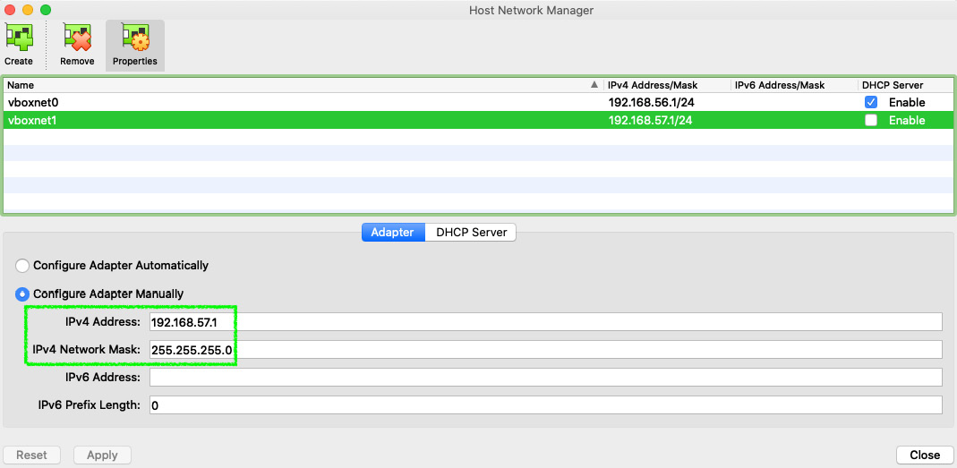
Figure 3.2 – VirtualBox Host Network Manager: creating a new network interface
Applying a New Network Configuration to Your OPNsense Virtual Machine
You must first shut down your virtual machine (VM) to apply the new network settings. Remember to note down the new IP address assigned in your new network interface on VirtualBox to use a different one in your new OPNsense interface configuration.
- After you have applied the new network interface in your VirtualBox, start your OPNsense VM again and log in to WebGUI to set it up. To do that, point to the Interfaces | Assignments menu.
- In New interface, select the desired NIC and then click the + icon to add the new interface, and after that, just click the Save button.
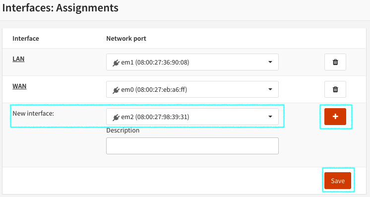
Figure 3.3 – Adding a new network interface in the OPNsense WebGUI
- After adding it, you can just click on the interface name or go to Interfaces | [New Interface Description] (OPT1 in the following example) to configure it.
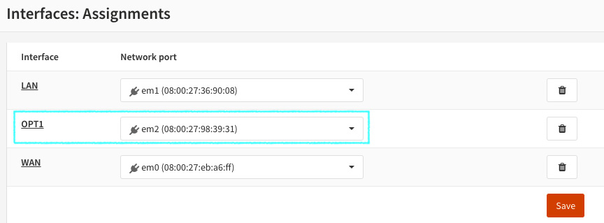
Figure 3.4 – New network interface added
Interface added! Let's practice a little bit now.
Proposed exercise – setting a static Ipv4 in added NIC
Now you have added a new network interface, let's add a static IPv4 to it:
Enable: Checked.
Description: Name your interface as you wish.
Block private networks and Block bogon networks: Unchecked.
IPv4 Configuration Type: Select Static IPv4.
IPv6 Configuration Type: Select None.
- Jump to Static IPv4 configuration:
IPv4 address: Fill with an address that is in the network range you noted down when you created the network interface on VirtualBox Network Manager. Pay attention to the network CIDR.
IPv4 Upstream Gateway: Leave as the default: Auto-detect.
- Click on the Save button.
Now that you have your new network interface configured in your OPNsense, let's take a closer look at it in our next section.
Overview of the network interface
Go to Interfaces | Overview and click on the interface you just configured. You should see something like this:
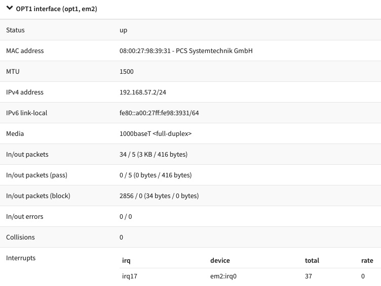
Figure 3.5 – Network interface overview
As we can see, there is some information in Interfaces | Overview that is quite similar to the ifconfig output, but with a much better look! We can check here, for example, whether the network interface is up, which IP address is configured in it, the MTU size, the MAC address, and a lot more useful information.
What about your interface overview configuration? Is it the same as the one you just configured in the previous exercises? If yes, congratulations! If no, then no problem, repeat the exercise, paying attention to the details, and I'm sure you will find the mistake and fix it!
Now that we have concluded the basic network configuration steps, we can continue our networking saga and head to the next section to explore the different types of network interfaces you can configure in OPNsense.
Types of interfaces
As a complete firewall solution, OPNsense supports many different types of network interfaces. We will explore each one available for configuration in WebGUI next.
Bridge
A bridge can connect two different network interfaces in the same network segment. For example, you can connect a LAN interface connected by cable to a Wi-Fi interface using a bridge. In this way, the devices connected in both interfaces will rely on the same broadcast domain or the same network segment.
GIF
The Generic Tunnel Interface, or just GIF, is a type of interface configuration that can be used to tunnel IPv6 via IPv4. An example of its usage is configuring it with the IPv6 tunnel broker from Hurricane Electric, with which you can reach IPv6 internet using an existing IPv4 connection. If you want to learn more about this service, you can access it at https://tunnelbroker.net/.
GRE
The Generic Routing Encapsulation (GRE) is a network configuration that allows two hosts to tunnel traffic without encryption. An example of its usage is when you need to traverse some protocols that aren't supported by the intermediate systems.
LAGG
Link aggregation, also known as port-channel sometimes, can provide, as the name suggests, aggregation using multiple network interfaces. It can be used to increase bandwidth in local networks with the prerequisite of a compatible device, such as a switch, for example. It can support failover since at least one interface is up. To perform these functions, LAGG will need to be configured on both sides of the connection, with the same protocol. The current protocols supported by OPNsense are as follows:
- LACP
- Failover
- FEC
- LoadBalance
- RoundRobin
Before starting LAGG configuration, check whether your switch supports one of these protocols. This feature is awesome when combined with VLANs, so that you can have a reliable trunk with a lot of networks passing through it.
Loopback
The loopback is a virtual interface that is commonly used to test local communications in a host. You can easily test it by trying to ping the 127.0.0.1 address (or ::1 for IPv6); this is supported in most modern operating systems, and FreeBSD is no different. In OPNsense, we can create additional loopback interfaces for different applications; for example, configuring a service only locally with the port listening in a loopback interface address.
VLAN
With VLANs, you can make better network segmentation, dividing one big network or broadcast domain into many smaller ones. By doing so, you can save your network from issues such as traffic flowing between all the hosts without any packet filtering, making it difficult for malware to spread to the whole network and preventing lateral movement, for example. Another example is to use a single network port to configure multiple network segments. OPNsense supports VLAN 802.1Q standard permitting VLAN tagging and priority code point, which can be used for Quality of Service (QoS). For extra protection, you may add network ports authentication using 802.1x. To learn more about 802.1X, please refer to https://en.wikipedia.org/wiki/IEEE_802.1X.
To learn more about network lateral movement, refer to https://en.wikipedia.org/wiki/Network_Lateral_Movement.
VXLAN
The Virtual Extensible Lan (VXLAN) was created to overcome VLAN limitations in this era of the cloud. It can address up to 16 million logical networks, while VLANs can do only 4,096. Most modern virtualization technologies support it, and its usage is more common in cloud scenarios. Now that we have seen the different types of interfaces, let's go ahead and create one of them, for example, the loopback interface.
Proposed exercise – creating another type of network interface
To practice how to configure another type of network interface, we will configure a new loopback interface using WebGUI:
- Go to Interfaces | Other Types | Loopback.
- Click on the + icon.
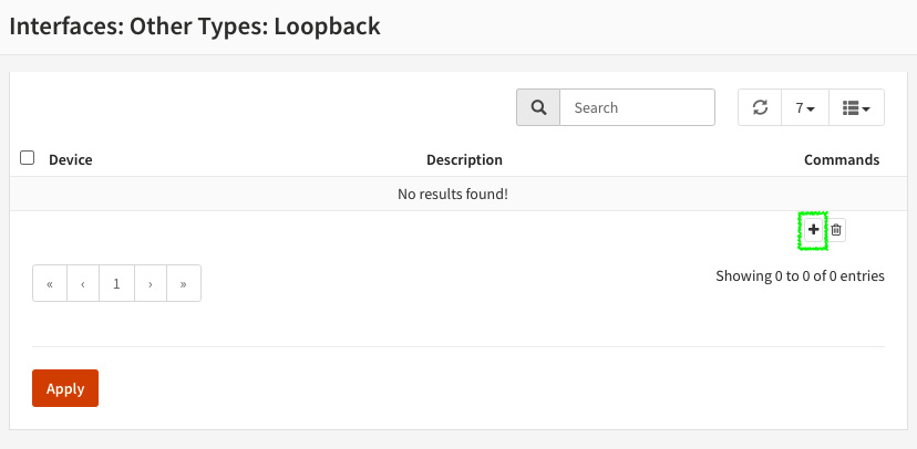
Figure 3.6 – Adding a new loopback interface
- In Description, enter something that will make sense to you, for example, loopback2. Then, click on the Save button and click Apply.
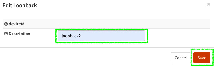
Figure 3.7 – Creating a new loopback interface
- Go to Interfaces | Assignments and add the new interface.
- Name your interface, adding a description such as LB2.
- Click on the new interface name.
- Enable it and set the static IPv4 address to 127.0.0.10/8 and leave the other options as default. Then, click on the Save button and click on the Apply changes button, which will appear in the top right.
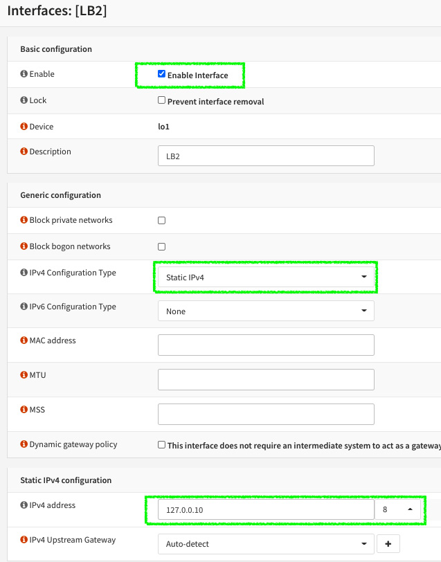
Figure 3.8 – Assigning the new loopback network interface
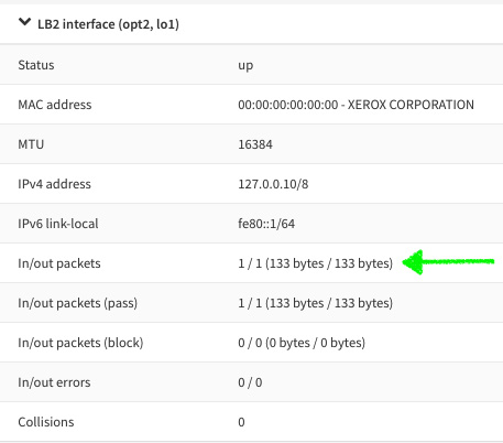
Figure 3.9 – Newly created loopback interface. Notice the In/out packets section
- Test it by sending a ping to the 127.0.0.10 address in Interfaces | Diagnostics | Ping.
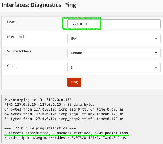
Figure 3.10 – Pinging the created loopback interface
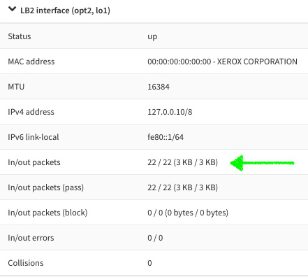
Figure 3.11 – Loopback interface overview: packets incremented after ping test
Adding a New Interface to OPNsense
You can review the steps on how to add a new network interface by looking at the Proposed exercise – adding a new network interface to OPNsense section in Chapter 2, Installing OPNsense.
Congratulations, you have created your first loopback network interface! You can repeat this exercise with other types of interfaces if you wish; the only difference is that each type will demand its specific configurations. I proposed using the loopback type to save your time to repeat all the required steps for creating a new network interface on VirtualBox, but it's up to you! You can repeat this exercise, creating as many types of network interfaces as you want!
As we explored in this topic, OPNsense can support a variety of types of network interface configurations. Now that you know about each one, let's dive into IP addressing, starting with how to add extra IPs in network interfaces.
Exploring virtual IPs
A virtual IP address can be used for a high-availability configuration, such as creating a Network Address Translation (NAT) in many different services on the same network port, or just for adding more than one IP address in the same network interface. In this section, we'll dive into each type of virtual IP that is supported by OPNsense and when to choose which virtual IP configuration type.
IP alias
An IP alias can be used as an additional IP address in a configured network interface. It will behave like the address configured in the interface, replying to ICMP requests (ping) and generating ARP packets on the network. The netmask must match with the network interface the IP alias will be created on; otherwise, you can set it as a single address (/32 CIDR for IPv4). You can even set an IP address from another network. There are some special cases, such as when the ISP delivers a small network (/30 CIDR) and you need to set up a high-availability installation. Instead, you should consider using VLANs, which will isolate the packets from the different networks configured within the same network interface.
Loopback Interfaces
An IP alias is the only type of address accepted to be used as a virtual IP address on loopback interfaces.
CARP
The Common Address Redundancy Protocol (CARP), as its name suggests, is a protocol used for network redundancy, and in OPNsense, we use it for high-availability deployments. We will explore this protocol and the high-availability configuration in detail later in Chapter 17, Firewall High Availability.
Proxy ARP
Wikipedia defines ARP as follows: “The Address Resolution Protocol (ARP) is a communication protocol used for discovering the link layer address, such as a MAC address, associated with a given internet layer address, typically an IPv4 address.” A proxy ARP uses this protocol (ARP) to reply to queries for an IP address set in the network interface using this configuration. The IP address will not be added to the interface. OPNsense will use the cheap and omitted proxy ARP daemon (choparp –https://www.freebsd.org/cgi/man.cgi?query=choparp) to reply to requests to the configured proxy ARP IP address.
Proxy ARP – Important Notes
To configure a single IP address, you must use /32 CIDR. Only network addresses will be accepted with smaller CIDR numbers.
When a proxy ARP IP address is configured, it will not be shown in Interfaces | Overview or in the ifconfig command output.
It does not respond to ICMP requests.
Other
The exclusive usage for this type of virtual IP is in NAT, since it will respond neither to ICMP nor ARP requests.
The Interfaces | Virtual IPs | Status page is exclusively used to show the status of CARP virtual IPs; hence, we will explore it later in Chapter 17, Firewall High Availability.
Proposed exercise – creating a virtual IP address
Let's practice how to create a virtual IP address by adding an extra IP to our previously created network interface, using the following steps:
- Go to Interfaces | Virtual IPs | Settings and click on the Add button.
- For Mode, leave the default option: IP Alias.
- In Interface, select the previously created loopback interface (see the Proposed exercise – creating another type of network interface section).
- In Address, enter 127.0.0.20/8.
- Leave the other options with their default values and click on the Save button and then on Apply changes.
- Go to Interfaces | Overview and see the newly created virtual IP address configured in the created loopback interface.
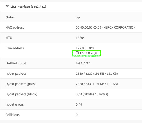
Figure 3.12 – Interfaces overview: virtual IP alias added
- Go to Interfaces | Diagnostics | Ping and try to ping the newly created IP alias.
If the ping replies, you just created a new IP alias successfully! Otherwise, repeat the exercise by reviewing each step carefully to get it working.
Now that we have learned about the OPNsense networking configuration, it's important to see how to troubleshoot some common issues involving network and connectivity. Let's explore some common issues in the next section.
Network diagnostics and troubleshooting
It's important to know how to configure network interfaces in OPNsense, but it is more important to know how to solve problems related to it. In this section, we'll explore the common issues and see how to solve each one.
First of all, let's see what diagnostic tools are available in WebGUI.
All of the following options can be accessed from Interfaces | [tool name]:
- ARP Table: This page lists the operating system ARP table, in which you can find the IP and MAC addresses listed in the following fields:
- Device Manufacturer, based on MAC OUI (organizationally unique identifier)
- Interface, using the FreeBSD NIC name
- Interface Name, using the configured one in the OPNsense interface description
- Hostname, if it resolves hostnames
- NDP Table: Like the ARP Table page, this page will show the same information fields, but for IPv6 addresses based on the Neighbor Discovery Protocol (NDP). Due to the similarity with ARP, you can use the previous ARP troubleshooting examples to solve issues but using the NDP Table page for IPv6 networks.
Let's now explore troubleshooting examples.
True story – how to use ARP Table diagnostics
Someone calls you and complains that the firewall stopped working. You ask about the symptoms that made this person believe that. Immediately the person tells you that all the local network hosts lost connectivity with the firewall, but they can access the firewall from another network interface, a WAN interface, for example, and it appears to be working as it was meant to be.
Well, based on a true story, I can tell you that it is a good prompt to start looking at the ARP table – why? Because if you look at it, you will probably find the possible reasons and see whether they are related to OPNsense, or you can call the network infrastructure team to check the switch connected to this firewall.
If the ARP table isn't showing the amount of entries that you expected, the next step will be to check whether the LAN interface is up; if it's not, it is probably a problem with the network cable or switch. Otherwise, the LAN interface port may be damaged, and you will need a new one; only a physical test will help in this case. Even if the LAN interface is up, it's a good idea to ask for help from the network infrastructure team, if there is a high chance that it's a problem with network connectivity.
These are some possible solutions:
- Check whether the network port is up. Where do you find it? As we learned earlier in this chapter, go to Interfaces | Overview and check its status.
- Check cable connections, switches, and test the LAN physical network port in your OPNsense hardware.
The DNS Lookup page will resolve DNS names to IP addresses; you can use it to find issues with DNS resolution.
Common issue – local network hosts can't open websites
After the initial tests, such as pinging the firewall and other internet IP addresses, the users are still complaining that they can't access websites or receive emails on their Outlook. Is this another true story? Most of the stories in this book are!
As you are not using a web proxy (because we haven't got there in this book yet), you can start trying to resolve the internet DNS names in the DNS Lookup page. If the DNS Lookup did not succeed, then ask a friendly user to try to do the same on their computer, you're probably dealing with a DNS issue. This page can be more useful than a command-line ping because it shows the query time for each DNS server configured in OPNsense; sometimes, the issue is related to slow responses from one of the configured DNS servers.
Here are some possible solutions:
- Check whether the hosts with DNS issues are using the same DNS servers configured in OPNsense or using one of OPNsense's local network addresses as the DNS server.
- Test connectivity between OPNsense and the configured DNS servers.
- Try to change the DNS servers configured in OPNsense.
- See whether there are any DNS names resolving to IPv6 addresses (while the host isn't configured to use IPv6); if your network is IPv4-based, this can cause some issues.
Let's go back to the diagnostics tools:
- The Netstat page shows the following:
- network interface
- bpf
- protocol, sockets
- Netisr
- memory statistics
- status
Since this topic is focused on troubleshooting, let's use the netstat command in the CLI instead of using WebGUI page.
Some examples of the netstat command usage are as follows:
- List the TCP ports state:
root@OPNsense:~ # netstat -ap tcp
Active Internet connections (including servers)
Proto Recv-Q Send-Q Local Address Foreign Address (state)
tcp4 0 0 OPNsense.ssh 192.168.56.1.58376 ESTABLISHED
tcp4 0 0 localhost.rndc *.* LISTEN
tcp4 0 0 *.domain *.* LISTEN
tcp6 0 0 *.domain *.* LISTEN
tcp6 0 0 *.http *.* LISTEN
tcp4 0 0 *.http *.* LISTEN
tcp6 0 0 *.https *.* LISTEN
tcp4 0 0 *.https *.* LISTEN
tcp4 0 0 *.ssh *.* LISTEN
tcp6 0 0 *.ssh *.* LISTEN
- List the UDP ports state:
root@OPNsense:~ # netstat -ap udp
Active Internet connections (including servers)
Proto Recv-Q Send-Q Local Address Foreign Address (state)
udp4 0 0 127.0.0.20.ntp *.*
udp6 0 0 fe80::1%lo1.ntp *.*
udp4 0 0 OPNsense.ntp *.*
udp4 0 0 localhost.ntp *.*
udp6 0 0 fe80::1%lo0.ntp *.*
udp6 0 0 localhost.ntp *.*
udp6 0 0 fe80::a00:27ff:f.ntp *.*
udp4 0 0 OPNsense.ntp *.*
udp4 0 0 OPNsense.ntp *.*
udp6 0 0 fe80::a00:27ff:f.ntp *.*
udp4 0 0 OPNsense.ntp *.*
udp6 0 0 fe80::a00:27ff:f.ntp *.*
udp4 0 0 *.ntp *.*
udp6 0 0 *.ntp *.*
udp4 0 0 *.domain *.*
udp6 0 0 *.domain *.*
udp6 0 0 *.dhcpv6-client *.*
When you are not sure of whether a configured service is listening at the correct port, you can use the preceding commands.
- List active network routes on OPNsense:
root@OPNsense:~ # netstat -nr
Routing tables
Internet:
Destination Gateway Flags Netif Expire
10.0.2.0/24 link#1 U em0
10.0.2.15 link#1 UHS lo0
127.0.0.1 link#5 UH lo0
127.0.0.10 link#8 UH lo1
127.0.0.20 link#8 UH lo1
Internet6:
Destination Gateway Flags Netif Expire
::1 link#5 UH lo0
fe80::%em0/64 link#1 U em0
fe80::a00:27ff:feeb:a6ff%em0 link#1 UHS lo0
fe80::%em1/64 link#2 U em1
If you want to know whether an added route or the correct default gateway is active, this command can help you!
- Packet Capture: This page will use the tcpdump command to capture packets, using which you can do some network packet sniffing to look for possible problems with protocols or the network. It's a lot easier than using the tcpdump CLI syntax and can help you in a lot of situations.
If you want to know whether a packet is flowing in some specific interface, with Packet Capture, you can find out.
- Ping: The classic network test tool; this uses the ICMP protocol to test whether a host is responding or not.
If you need to test whether a remote host is online or not, a good starting point is trying to ping it.
Note
Windows' default configuration blocks ICMP packets. If you are testing against Windows machines, be sure that they are allowing ICMP packets.
- Port Probe: This page will try to connect to a TCP port to test whether it is connecting or not. It uses netcat (nc) to do that and is very efficient. If some TCP port isn't responding to a NAT rule, then you can use it to test the destination host port from OPNsense.
- Trace Route: This page will use traceroute(6) to test a network packet's path trying to reach a host. Windows uses ICMP in the tracert utility; be sure that ICMP packets are allowed before using it.
Say your users are complaining about a single website that isn't accessible. One good starting point is trying to reach it using traceroute. We already saw cases where changing the WAN, or the network route, solved the problem. Sometimes the ISP's cloud can be very tricky, and when you have another ISP available, changing the route to a second one is worth trying! Another good example is when the traceroute output shows the same IP multiple times; in this case, we have a routing loop.
We'll explore some of these diagnostic tools in depth in later chapters, which will present you with some examples of how to use them practically, so don't worry – we have a long journey ahead of us!
Summary
In this chapter, we learned how to design an OPNsense firewall for a production environment, considering which hardware and network card to use depending on the features that will be enabled. We learned about the FreeBSD network interfaces and practiced some CLI network commands. We also saw how to add new IP addresses to OPNsense using virtual IPs, choosing the right type depending on its usage. In the last section, on diagnostics and troubleshooting, I tried to share with you a little bit of my experience, telling you some true stories about network issues with some examples of how to solve them.
In the next chapter, we'll learn how to manage our OPNsense system configuration using WebGUI.