9.2. History of Routing
In this section, we review the routing architectures and their evolution in two of the largest networks in existence—the telephone network and the Internet. Routing in the circuit-switched telephone network is in many ways similar to routing connections in an optical network, which is also a circuit-switched network. Although some aspects of routing in the packet-switched Internet are similar to those of routing in telephone and optical networks, many differences exist. Different standards bodies are working on defining more sophisticated IP-centric routing protocols for routing connections in optical networks.
9.2.1. Routing in the Telephone Network
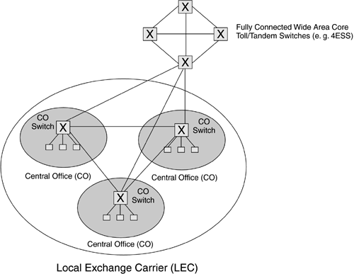
Figure 9-1 shows the architecture of today's telephone network [Briley83]. As shown in the figure, it is a three-layer hierarchy consisting of central offices (CO), local exchange carriers (LEC), and fully connected wide-area core networks. LECs may connect to multiple wide-area cores. If the two end points of a call are in the same CO, then they are directly connected. If the two end points are in different COs within the same LEC, then the call is routed over the single-hop path between the COs. If the two end points are in different LECs, then the call is routed through the core. In the following we discuss the evolution of routing in telephone networks.
Figure 9-1. Telephone Network Architecture

Routing in the core uses either one-hop or two-hop paths. Note that the core is fully connected. The direct one-hop path between the originating and the terminating switch is considered to be the primary path between them. If the primary path between a pair of switches is available, then the call is routed over that path. If the primary path is not available, then the call is routed over one of the alternative two-hop paths. In that case the routing problem boils down to which two-hop path to use.
The early telephone network relied on static one-hop routing in the core. Under this scheme the path between the source and the destination switches remained fixed independent of the state of the network. The network was overprovisioned since a given fixed route had to be dimensioned to handle the peak-hour traffic. A call was dropped if the selected path was busy. Static routing in the telephony network was found to be too rigid and inefficient.
After the introduction of digital switches, static routing in the core was replaced by dynamic routing. Dynamic routing alleviated the routing inflexibility with static routing so that the network would operate more efficiently. Dynamic routing also improved network resilience by permitting the calculation of routes on a per-call basis and the periodic updating of routes. Three types of dynamic routing schemes have been designed for use in the telephone network. These are:
Event Dependent Routing (EDR): Under EDR, routing changes are triggered by events such as call set-up attempts failing due to congested or blocked links. In these instances, new routes are established using learning models. EDR methods are real-time adaptive, but, unlike SDR, they do not require global state information.
Dynamic Non-Hierarchical Routing (DNHR) [Ash97] is an example of TDR. DNHR was introduced in the AT&T network in the 1980s to respond to time-dependent information such as load variations. Under DNHR, a day is divided into ten time periods. For each time period, each switch is assigned a primary one-hop path and an ordered list of alternate two-hop paths for every destination. DNHR thus adopts a “two-link” approach described earlier, whereby a path can consist of at most two hops. If a call cannot be routed over a selected route due to the unavailability of resources, the originating switch selects the next route in the list, and so on, until the call is routed or there are no alternate routes available. In the latter case, the call is blocked.
Route assignment in DNHR takes into account the network load over different time scales. Correspondingly, different routing schemes are used to pre-plan the routing tables. The network design algorithm operates over yearly intervals while the demand-servicing algorithm operates on a weekly basis to fine-tune link sizes and routing tables. At the smallest time scale, the routing algorithm is used to make limited adjustments based on daily traffic variations. DNHR works well when traffic is predictable. For bursty and unpredictable traffic, the network may enter into a situation where spilled calls from overloaded links can block calls on direct links. This problem is addressed by using link reservation, whereby some links are reserved for direct calls only.
Real Time Network Routing (RTNR) [Ash97] is another dynamic routing algorithm used in today's telephone network. Under RTNR, each switch maintains a list of lightly loaded links that terminate on that switch. The intersection of the lists at the source and the destination switches is the set of lightly loaded paths between the source and the destination. For example, consider two switches—1 and 2. Let us assume that the set of lightly loaded links terminating on switch 1 are 1-3, 1-4, and 1-5, where 3, 4 and 5 are other switches. Hence, switch 1 maintains the list, {3,4,5} . Let us also assume that the set of lightly loaded links terminating on switch 2 are 2-3, 2-6, and 2-7, where 6 and 7 are two other switches. Consequently, the list maintained by switch 2 is {3,7,8} . Now, if a call has to be routed from switch 1 to switch 2, switches 1 and 2 exchange their lists with each other. The intersection between the two lists is switch 3. Hence, 1-3-2 is a good alternate (two-hop) path between switches 1 and 2. RTNR works very well in practice resulting in very few blocked calls.
Despite their common roots in circuit switching, routing in telephone and optical networks are subject to different requirements. The topology of telephone networks is rather restricted, that is, complete mesh in which the routes are at most two-hops long. An optical network, on the other hand, can have a general mesh topology with routes longer than two hops. In this regard, optical networks are similar to IP networks. This is one of the reasons why IP routing protocols, rather than telephony routing protocols, have been extended to route connections in optical networks.
9.2.2. Routing in the Internet
Unlike telephone networks, the Internet does not have a rigid structure. It is a collection of networks that are interconnected at various peering points (see Figure 9-2) [Halabi+00]. Different Internet Service Providers (ISPs) manage this collection of networks. The peering points are the points where the ISPs exchange traffic from each other. Depending on the size and the reach of their networks, ISPs can be classified into different tiers. Tier 1 ISPs are the Global/National ISPs that are the top of the ISP hierarchy. Tier 1 ISP networks are connected to each other at various public and private peering points and form the backbone of the global Internet. Tier 2 and Tier 3 ISPs are typically the regional and local service providers and their networks are connected to the Internet through Tier 1 providers. Tier 2 and Tier 3 providers also peer with each other at different private and public peering points. We should note here that the peering relationship is typically an agreement of equals, whereby service providers exchange traffic from each other when the volume of traffic flowing in each direction is approximately equal. For asymmetric traffic flow, ISPs often strike transit relationships, whereby a smaller ISP sends traffic through a lager service provider for a transit fee. Businesses and individual customers are connected to the Internet through ISPs. Businesses are often connected to multiple service providers for reliability.
Figure 9-2. General Structure of the Internet

From a more technical point of view, the Internet is a collection of “autonomous systems” or ASs. From a control plane point of view, an AS is similar to a control domain described in Chapter 5. It is defined to be the collection of IP networks managed by a single organization. The definition of an organization is fairly loose. It can be a service provider, a company, or a university. Many organizations span multiple ASs. Some organizations do have their own AS(s). Neighboring ASs are connected to each other as peers through private and public Internet exchange points. Two ASs may also have a customer and a provider relationship when traffic from the customer AS transits through the provider AS. Neighboring ASs may exchange information about reachable destinations with each other. They do not, however, exchange internal topology information. There is a large number (approximately 11,500) of ASs with different sizes in the Internet.
