Chapter 7
The Basics of Batteries
IN THIS CHAPTER
![]() Taking a peek at the guts of a battery and discovering what makes one tick
Taking a peek at the guts of a battery and discovering what makes one tick
![]() Getting to know the various battery technologies
Getting to know the various battery technologies
![]() Becoming familiar with the concept of capacity
Becoming familiar with the concept of capacity
![]() Knowing what to consider when selecting batteries for a client
Knowing what to consider when selecting batteries for a client
So your clients want to store energy? For PV systems, the need for energy storage leads most people to battery banks. With the exception of petroleum-based fuels, batteries are currently the most practical and cost-effective way to store enough energy for human use. Fortunately, you can incorporate batteries into virtually any PV system.
- If the utility grid is present, you can design a utility-interactive, battery-based PV system, also known as a battery-backup PV system. In this system, batteries are used only when the utility grid fails.
- In the absence of the utility grid, you can design a stand-alone (or off-grid) system. Batteries in this system are used when the PV array can’t provide all the power draw for the loads at any specific time (cloudy weather, nighttime, or if a number of loads are running during the day). Stand-alone systems can actually go a step further and incorporate multiple battery-charging sources in addition to the PV array (think wind- or water-powered generators and fuel-based AC generators).
In this chapter, you get to see the types of batteries being used in PV systems. Here’s your chance to explore their basic functions and features and get to know the fundamental criteria used to choose battery banks for PV systems.
 Even if you think you’ll never install a battery throughout the course of your PV career, you should still know all about the design and installation components regarding batteries. Offering this service will increase demand for your work because clients will see you as a true expert.
The Fundamentals of Battery Anatomy and Operation
When I talk about batteries, I like to refer to them as buckets of energy. Batteries are a convenient way to store electrical energy for people to use at will. More accurately, batteries are a group of cells that store electrical energy and, through a chemical reaction, can deliver power to loads. In the following sections, I introduce you to the typical components and operation of the batteries used in PV systems.
Constructing a battery, from cell to bank
The fundamental construction of individual batteries and how they’re grouped together is very similar to the solar cells, PV modules, and arrays I describe in Chapter 6. For batteries, the most basic portion is the battery cell. Battery manufacturers take these battery cells and make batteries of various electrical and physical characteristics. As an installer, you take these individual batteries and make a battery bank to serve the needs of your client.
Going cellular
Just as solar cells are the basic building blocks of PV modules and arrays (as I explain in Chapter 6), battery cells are the basic building blocks of battery banks. Each battery cell has a specific voltage potential; this voltage value is dependent on the battery technology but independent of the cell’s size. The amount of energy stored is directly proportional to the cell’s size, though; in other words, the bigger the cell, the greater the amount of stored energy or capacity (I cover capacity in greater detail later in this chapter).
Battery cells designed for PV systems are configured by the battery manufacturer to produce a desired voltage and store a desired capacity. Every cell has either a single plate with positive and negative sides or multiple positive plates and negative plates together within an individual compartment. The negative plates are separated from the positive plates by a special electrically insulating material. Each plate holds the active material, which is the material that reacts in the chemical process I describe later in this chapter. These plates are then immersed in an electrolyte, either a liquid or a gel, that allows the charged particles to flow between the positive and negative plates when given an electrical path in which to move, such as a DC load connected to the batteries or an inverter that’s running AC loads.
If multiple plates are used in a cell, all the negative plates are connected together with a metallic bar, and all the positive plates are connected together with a similar metallic bar, creating parallel connections within the cell. Depending on the desired effect, many thin plates or a few thick plates may be together in a cell.
- Multiple thin plates allow for an increased amount of surface area of the active material in contact with the electrolyte, creating a greater amount of current flow in a short period. These batteries work well as starting batteries (like the one found in your car).
-
 A few thick plates allow a battery to move from charged to discharged many times without damage (unlike batteries with multiple thin plates). If your system design calls for a battery to run electrical loads continuously, you need a deep-cycle battery (also known as a deep-discharge battery). A deep-cycle battery’s thick plates allow it to deliver nearly all the energy stored and then be recharged fully. All the batteries used in PV systems are deep-cycle batteries because they’re expected to deliver a majority of their capacity many times in their lives.
You can see multiple plates in a battery cell in Figure 7-1.
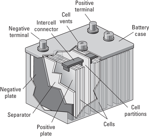
FIGURE 7-1: The construction of a typical PV system battery.
Making a connection to create a battery
To create a battery, multiple battery cells are connected together within a case. The exact number of cells connected together varies by manufacturer, but the most common configurations result in 6 V and 12 V nominal batteries. The nominal designation indicates that the batteries are close to that voltage but can vary (I tell you about nominal voltages in Chapter 3).
The exact voltage and capacity of a battery depend on the technology used, but you can gain some quick knowledge just by looking at the top of a battery case. Each cell has its own vent, so if you look at a battery and see three vents, you know that three individual cells are in that battery.
Taking it to the bank
Typically, individual batteries don’t have the required voltage and capacity values necessary for an entire PV system, which is why you must connect them to create a battery bank (the total number of batteries used). By wiring batteries in series, you create a string of batteries, which allows the voltage to increase while the capacity remains constant. This concept is identical to the PV series string connections I show in Chapter 3.
If you require additional capacity, you can create multiple strings of batteries and place them parallel to each other. Doing so allows you to keep the voltage constant while increasing the overall capacity of the battery bank. (I explain how to properly size a battery bank later in this chapter.) This practice is the same as the parallel connections for PV strings I show in Chapter 3.
Discovering how batteries charge and discharge
Batteries store energy in the form of direct current (DC; see Chapter 3 for an introduction). This is the same form of current delivered by PV arrays, which means batteries can be charged directly from a PV source with minimal losses. A charge controller makes this charging possible. I fill you in on charge controllers in Chapter 8, but in the sections that follow, I describe the fundamental concepts of charging and discharging and explain the basic chemistry of the charging and recharging processes.
Getting a grip on the concepts of charging and discharging
Deep-cycle batteries (described in the earlier “Going cellular” section) are designed to deliver nearly all of their stored energy to loads in a PV system, but limitations exist. The phrase depth of discharge (DOD) describes the amount of energy drawn from the battery. For most deep-cycle batteries, the maximum DOD you want to experience is 80 percent, meaning you remove 80 percent of the stored capacity from the battery. Although deep-cycle batteries are designed to deliver as much of their stored energy as possible, if the DOD frequently reaches a high value, such as 80 percent, the overall battery life will be reduced. Therefore, increasing a battery bank’s overall life while delivering as much energy for the loads as possible becomes a balancing act that you, as the PV system designer and installer, must master.
The opposite term for DOD is state of charge (SOC), and it reflects the amount of energy still stored in a battery. So if I say a battery has an SOC of 20 percent, then I’m telling you that the battery has delivered 80 percent of its energy and has 20 percent of it left. This is another way of saying the battery has an 80-percent DOD. Because these terms are the opposite of each other and PV folks refer to them most often in percentages, a handy trick for remembering the relationship is that SOC + DOD = 100%.
All batteries designed for use in a PV system are rated by their voltage and capacity as well as by how many cycles they can deliver that energy. A cycle is when the battery goes from being fully charged to fully discharged and then recharged again. The exact number of cycles a battery can undergo during its life is affected by a number of factors, including temperature and how fast the battery is being discharged (these factors also affect the battery’s capacity, as I explain later in this chapter). Typically though, battery manufacturers relate the number of cycles a battery can withstand against the DOD. So, logically, the greater the DOD a battery experiences, the fewer cycles it’ll experience.
Understanding basic charge and discharge chemistry
Batteries are able to deliver electrical current to loads in a PV system through a chemical reaction that’s contained within that battery. The exact chemical reaction is dependent on the type of battery used and the materials used to push the electrons around. You don’t need to get too hung up on the chemical reaction I show in Figure 7-2 (unless you do chemistry in your spare time for fun). All you need to take away is how the electrons move from one side to the other depending on whether the battery is charged or discharged.

FIGURE 7-2: The chemical reaction that occurs when discharging and charging a battery.
On the left side of Figure 7-2 is a chemical equation for a fully charged battery composed of lead, lead oxide, and sulfuric acid (this type of battery is a lead-acid battery; see the later related section for details). As the battery is discharged, the lead and lead oxide become lead sulfate, and the sulfuric acid becomes water. So a fully discharged battery contains lead sulfate and a very watery acid solution (see the right side of Figure 7-2). The electrons don’t go away; they merely move to a different form and are stored in the lead sulfate.
During the charging cycle, the lead sulfate breaks up, lead oxide re-forms, and the water becomes a strong acid again. Hydrogen gas is also released into the atmosphere, although the amount of gas released varies greatly among battery technologies. As for the electrons, they move similarly to the way electrons move in solar cells (see Chapter 6). During the charging process, current is applied into the batteries to force the electrons back. When the electrons are back where they started, they look for a way to return to the other side. You provide this path with a load, and the whole process repeats.
In theory, the recharging portion of the battery cycle should remove all the lead sulfate that has accumulated on the plates and return it to the sulfuric acid solution. However, that’s not the reality. In real life, the plates become corroded as batteries age. In the case of lead-acid batteries, that corrosion is in the form of sulfation, and it reduces the batteries’ ability to store as much energy as they did when they were new. As a result, lead-acid batteries become discharged quicker and appear to recharge quicker, but they’re really not performing at their optimal effectiveness.
The best way to prevent corrosion in a battery is to follow the charging cycles specified by the manufacturer when you set the charging levels for the different battery-charging sources (PV array, utility, and generator).
 Batteries aren’t smart creatures by any means, and they can’t differentiate between wires connected to their terminals and a load or wrench that was accidentally dropped across their terminals. If you ever drop a wrench across a battery’s terminals, the battery will short-circuit and discharge very quickly because the electrons start flowing through the wrench from the negative plates directly back into the positive plates. Ideally the only damage will be to the wrench and the battery, but if you get caught in the path, you’re in serious danger. To avoid this scenario, only use tools that are specifically made for use on batteries. You can buy tools that have specially insulated handles to protect you from connecting the positive and negative terminals.
Charging correctly
As an installer, you need to make sure the pieces of equipment used to charge the battery bank — the charge controller and inverter — are set up so that the charging voltages and current values are correct. These values depend on the battery technology, overall battery bank size, and the battery temperatures. Consult the battery manufacturer’s requirements and the charge controller and inverter installation manuals to set the charging points correctly, and flip to Chapter 8 to see the steps a battery goes through when being recharged.
Comparing Different Types of Batteries
Even though a number of battery technologies are available commercially, relatively few are found in PV systems. The next sections get you familiar with the types of batteries that are regularly used in PV systems and help you differentiate among them to make the selection process a little easier.
Lead-acid batteries
Far and away the most common type of battery used in PV systems, the lead-acid (LA) battery has been around since the 1860s and commercially available since the turn of the 20th century. In LA batteries, the active material used on the negative and positive plates is lead and lead oxide (sometimes with small amounts of antimony added); the electrolyte that allows charges to flow in LA batteries is sulfuric acid. Each cell is approximately 2.12 V when fully charged, so the cells in LA batteries are referred to as 2 V nominal.
LA batteries are so popular in PV systems due to their relatively low cost, robust design, and ability to achieve a high depth of discharge. LA batteries are available in either flooded or valve-regulated versions; both types have their pros and cons, as you find out in the following sections.
Flooded lead-acid batteries
As the name implies, flooded lead-acid (FLA) batteries have a liquid electrolyte inside them that floods the cells. These batteries have removable caps on each cell and require the person maintaining the batteries (typically the system owner) to check the electrolyte level regularly and add distilled water when the fluid level begins to get low (I explain how to perform this task in Chapter 18). FLA batteries work well in stand-alone systems in which the batteries are cycled on a regular basis; they hold up better than their sealed counterparts in this environment of constant cycling because they’re designed for more regular cycling and can accept maintenance charging (as I describe in this section). FLAs are much more cost effective for stand-alone clients; the additional maintenance is more than offset by the increased battery life they’re able to achieve in these environments.
FLA batteries require a high level of client interaction and maintenance if you expect them to last as long as possible and perform to their specifications. Why? As I describe in the earlier “Understanding basic charge and discharge chemistry” section, the chemical reaction that occurs during the charging process creates hydrogen gas and reduces the amount of water in the battery. Because flooded cells need to remain immersed in the electrolyte solution (when they’re not, they become damaged beyond repair), the client must add distilled water to the cells on a regular basis. When properly maintained, an FLA battery bank should perform for ten years or more.
FLA batteries also require a periodic intentional overcharge, or equalization charge. This process involves intentionally increasing the charging voltage into the batteries to stir up the electrolyte solution and “scrub” the sulfation (corrosion) that accumulates on the plates. During this process, the batteries produce large amounts of hydrogen gas, and you smell rotten eggs. Every battery manufacturer has its own recommendation for the time between equalization charges and voltage levels.
An equalization charge must always be performed in a controlled and regulated manner. If the system owner is properly trained and feels comfortable with this task, he can take it on. Otherwise, you, as the system installer, should make arrangements to provide this service on a regular basis.
I explain how to equalize flooded batteries in Chapter 18, but you should know that before you even begin the equalizing process, you need to remove the battery cell covers to allow the extra hydrogen gas to escape easily and check that the batteries are venting to the outside (preferably through the use of a brushless fan) to reduce the possibility of fires — after all, hydrogen is a very flammable gas. Also, make sure you place the proper signs in the battery bank’s location to warn others about the potential fire and explosion hazards.
Valve-regulated lead-acid batteries
The other type of lead-acid battery used in PV systems is the valve-regulated lead-acid (VRLA) battery. Also known as a sealed lead-acid battery, VRLAs are sealed from the environment and possess no internal components that the client must maintain. The valves on the individual cells keep the batteries sealed but also allow gas to escape when necessary. As a VRLA charges, the chemical process produces small amounts of hydrogen gas and increases the pressure within the battery. As soon as the pressure reaches a certain level, the valve is pushed up, the hydrogen gas “burps” out, and the valve resets.
VRLA batteries are quite popular in utility-interactive, battery-based systems. They generally aren’t cycled on a regular basis because, in most locations, the grid is relatively stable and power outages are the exception, which means the batteries are sitting in a constant state of full charge. (Note: VRLA batteries should be cycled every three to six months to help increase their life span, but they aren’t hurt by sitting fully charged a majority of the time.)
Other positive reasons for using VRLA batteries in utility-interactive, battery-based systems are as follows:
-
Reduced maintenance: VRLA batteries need less maintenance than FLA batteries because they don’t require watering. Considering the fact that most homeowners have a difficult enough time remembering to change the filter in their furnace, not having to worry about adding water to a PV system’s batteries is a major plus.
The reduced maintenance aspect of VRLAs has also led to the misnomer “maintenance-free batteries.” Yes, it’s true that you don’t have to add water to the cells, but VRLAs still need monitoring and evaluation on a regular basis if your client expects them to last within his PV system. Hearing the words maintenance-free batteries makes people feel as if they never have to think of the batteries again, so avoid using these words and stick with the term valve-restricted or sealed. To help a client with VRLAs stay on top of their performance, have him cycle the battery bank once or twice every six months and monitor the energy delivered by the system. This exercise helps the client establish the health of his battery bank and gives him an idea of the bank’s capacity for the times when the batteries really need to perform. - Less hydrogen gas: VRLAs don’t produce as much hydrogen gas as FLAs, which can make placing them an easier task because the venting requirements are less restrictive.
- Stackability: VRLAs are stackable, a characteristic that allows you to use vertical space (along a wall, for example) rather than a large amount of floor space.
With all the benefits of VRLAs, you may wonder why anyone wouldn’t want to use them. Well, VRLAs have a few downsides to consider:
- Excessive charging is a no-no. VRLA batteries can’t accept excessive charging voltages (unlike FLA batteries, which can). Because a VRLA battery may produce too much gas when exposed to higher voltages, its valve may not be able to effectively release the buildup and properly protect it. VRLAs therefore require careful charging per the manufacturer’s specifications, as well as monitoring to make sure the proper voltage levels are maintained.
- The expected life span is pretty short. A properly maintained and used VRLA battery should last from five to seven years. However, I’ve seen VRLA battery banks go bad in less than one year. Even though FLA batteries can also be ruined, they generally have the ability to withstand more abuse and come back to life to charge another day.
- The cost is greater. VRLA batteries cost considerably more than their FLA equivalents, which makes them a greater expenditure now and in the (relatively) near future.
Lead-calcium batteries
Lead-calcium batteries, which add calcium to the active material of the battery rather than antimony, are another type of battery used in PV systems, and they come in both flooded and valve-regulated varieties (see the previous sections). Lead-calcium batteries are 6 V and 12 V nominal, just like lead-acid batteries, and the capacities are dependent on the manufacturer and the physical dimensions of the battery. The addition of calcium to the active material reduces water consumption, makes the plates more resistant to corrosion, and decreases the battery’s self-discharge rate.
All of these advantages come at a cost, though: Lead-calcium batteries are more expensive than their lead-acid counterparts. Also, few companies manufacture deep-cycle lead-calcium batteries at this time, which makes them less popular than the traditional lead-acid batteries.
Nickel-cadmium batteries
Nickel-cadmium batteries (which are often referred to as NiCd batteries) have been used as rechargeable batteries for many years now. Nickel oxide hydroxide and metallic cadmium are the base materials for the positive and negative plates, respectively, and potassium hydroxide is the electrolyte in the cells. These batteries are manufactured in both valve-regulated and flooded varieties (see the earlier related sections), and they come in 6 V and 12 V nominal configurations, like the other batteries I cover in this chapter. However, they provide less voltage per cell, which means you need more cells in series in order to achieve this voltage. A 12 V nominal NiCd battery therefore has to have ten cells in series.
NiCd batteries aren’t widely used in PV systems, but they do have an advantage over other battery technologies in that they can be excessively discharged with less of an effect on the overall life of the battery. This characteristic means NiCd batteries can have an increased number of cycles during their life spans.
NiCds are more expensive than other types of batteries, which is a major drawback for many folks. In addition, they react worse to cold temperatures than lead-acid batteries do, meaning they need a temperature-controlled environment to perform at their best.
If you design a system that uses NiCd batteries, be sure to adjust all the charge set-points for the chargers due to the difference in charging voltages associated with NiCds. I cover the different charge set-points in Chapter 8.
Comprehending Battery Capacity
A battery’s capacity, the amount of energy stored in it, plays a large role in the overall design of PV systems and the use of batteries within them. In order to select the right battery for your client’s PV system, you need to have a solid understanding of how batteries’ capacity values are determined and reported and how to apply those ratings to the system you’re designing (I introduce you to this process of specifying batteries later in this chapter).
Batteries are rated according to the number of amp-hours (Ah) stored in them. Although this seems like an easy concept to grasp, multiple factors change this value. In the sections that follow, I describe a capacity rating called the C rate, and I explain the various factors that affect capacity.
Considering the C rate for capacity
In order to sell batteries, manufacturers have to put labels on the sides of their batteries that list the voltage and capacity of each unit. (The voltage depends on the type of battery and the cell count inside the battery; see the earlier “Comparing Different Types of Batteries” section for more.) They can’t very well say the capacity of their batteries is “around X Ah, depending on a number of variables,” but in reality, that’s precisely the case. Just like PV modules (which I cover in Chapter 6), the characteristics of a battery vary with the environmental conditions affecting it. And just like PV modules, battery manufacturers have to pick a point at which to rate their batteries.
Batteries used in PV systems are typically rated at a temperature of 25 degrees Celsius and at a discharge rate over a time period of 20 hours. This rate is referred to as the C rate and is notated as C/20 (C over 20). The C represents the capacity value, and the 20 represents the number of hours of discharge time. Many battery manufacturers use a C/20 rate, but some manufacturers use the C/24 value (for 24 hours) or something close to that.
Here’s a numerical example to help you make sense of the C rate: If a battery manufacturer lists its battery as a 100 Ah battery at the C/20 rate, you can do the math to figure out what kind of load that represents:
100 Ah ÷ 20 hrs = 5 A
This means that if a 5 A load were placed on that battery, in 20 hours the battery would deliver all of its stored energy and would no longer have any capacity. In reality, getting all 100 Ah out of that battery isn’t realistic because the battery can’t really deliver all of its capacity.
As I explain in Chapter 3, amp-hours aren’t really an energy measurement; that’s watt-hours (Wh). Amp-hours are actually the quantity of electrons that flow through a circuit in a given amount of time; as you discover in the earlier “Understanding basic charge and discharge chemistry” section, the electrons are always there — they just temporarily reside in different sections. You can gauge the capacity of a battery in watt-hours by multiplying the amp-hour value by the voltage, but this isn’t how battery manufacturers rate their batteries, so you have to make the conversions yourself.
The C rate can also describe the charging half of the cycle, but in this case you’re talking about replacing the capacity rather than drawing it out. For example: If I say that my battery charger has a C/10 rate, I’m saying that I’ll replace the entire capacity in a matter of ten hours. The best rate of recharge varies with battery technologies and even manufacturers. Finding the correct value is very important when sizing your charging sources, as I reveal in the later “Thinking about the rate and depth of discharge” section.
Recognizing factors that affect capacity
A battery is somewhat at the mercy of its surroundings when it comes to energy delivery. As you find out in the following sections, environmental conditions dictate a battery’s ability to deliver energy, as do the age and discharge rate of the battery. By understanding these factors, you can avoid costly mistakes that will require a battery replacement sooner than necessary.
Temperature
Temperature has a very significant effect on a battery’s ability to deliver and accept current.
- A cold battery has a reduced capacity due to the fact that the chemical reaction inside the battery is slowed down and isn’t as efficient.
- A hot battery has the ability to deliver a greater number of amp-hours because the heat actually aids the chemical process. However, increased temperature ultimately reduces a battery’s life, so intentionally keeping a battery hot to increase its capacity in the short term will only have the effect of reducing its life in the long term.
In a sense, batteries are a lot like humans. We’re finicky creatures who want things just the way we like them, and we’re pretty happy when we’re in an environment that’s around 25 degrees Celsius (77 degrees Fahrenheit — a pretty comfortable room temperature any time of the year). So spread the word to your clients! This is also the reason manufacturers rate their batteries at 25 degrees Celsius (as I cover earlier in “Considering the C rate for capacity”); it makes for a more impressive rating.
Ideally, the battery bank should be located in a temperature-controlled climate that’s around 25 degrees Celsius. In reality, this task is difficult. When helping your client decide where to place the battery bank, aim for a location that doesn’t experience extreme temperatures. A location such as an insulated garage that isn’t heated or cooled is a good choice.
Age
As a battery ages, the chemical reactions don’t work as well as they did when the battery was young and fresh from the factory. The active material on the batteries becomes layered with parts of the electrolyte that didn’t return into acid solution during the recharging process.
This aging process is evident in both the charging and discharging parts of a battery’s cycle. Aged batteries discharge quickly due to their reduced capacity. They also seem to finish recharging quickly due to the reduced amount of active material that’s actually available to the battery, allowing the battery to appear fully charged when it really isn’t.
A common question asked about battery banks and aging batteries is this: Can you install a new battery into a bank of older batteries? Adding a new battery to an existing battery bank isn’t a great idea because the old batteries drag the new battery down to their level in a short period, but depending on your client’s reality, it may be workable. So the question becomes this: What’s the state of the battery bank? If the bank is relatively young and well-maintained, the idea of adding a new battery to replace a failed unit may seem reasonable. If, on the other hand, the entire bank is on the verge of replacement in a short period, adding a new battery may not make any sense.
A bad battery makes itself known relatively quickly by dragging down the whole bank almost instantly. An aging battery bank, on the other hand, has a slow decline. When an aged battery bank can’t hold a charge for a required amount of time (as dictated by what your client considers acceptable), the whole bank needs to be replaced.
Discharge rate
A battery’s capacity is directly affected by the rate at which the battery is discharged. This rate is the theoretical number of amp-hours a battery could deliver to a load. So, for example, a 100 Ah battery could, theoretically, deliver 1 A for 100 hours (1 A × 100 hours = 100 Ah) or 100 A for 1 hour before it was completely discharged.
Because a battery delivers power via a chemical reaction, the slower the reaction, the greater the battery’s capacity. The opposite is also true: The faster the reaction, the smaller the capacity.
Figure 7-3 shows a typical graph of battery voltage versus energy delivered from the battery. The battery voltage is a good indicator of the battery’s state of charge (high voltage means there’s a high state of charge), so this graph shows the battery’s capacity (how full it is) versus how much energy has been delivered. Figure 7-3 shows that a slow discharge rate (C over the number of hours) results in a greater number of amp-hours delivered from the same battery than a fast discharge rate. So in reality, that 100 Ah battery delivers more than 100 Ah if the load is only 1 A; similarly, it delivers less than 100 Ah if the load is 100 A.

FIGURE 7-3: Battery capacity versus discharge rates.
As I mention in the earlier “Considering the C rate for capacity” section, battery manufacturers typically rate their batteries at the C/20 rate (or something very close to that). They then generally report the capacity values for their batteries at other C rates for your information so you can establish the discharge rate that most closely reflects your client’s load profiles and use the C rate in your designs accordingly. See Chapter 12 for full details on sizing and designing a battery-based PV system.
Specifying Batteries
When specifying (selecting) the batteries for a client’s PV system, you get to take all of your battery-related knowledge and sift through the available batteries to pick the type of battery that best meets your client’s needs. The sections that follow help you sort through this decision-making process.
Specifying the type of battery to use
The first question to ask when specifying batteries is, “What’s the right battery technology for my client’s system?” As I show you in the earlier “Comparing Different Types of Batteries” section, the vast majority of PV systems currently being installed use lead-acid batteries. However, a lead-acid battery isn’t your only option. In order to choose the right type of battery, you need to ask the key questions posed in the next sections.
What kind of PV system will your client use?
The type of system your client wants installed helps dictate the type of battery you need to use. In general, a utility-interactive system benefits more from sealed batteries than from flooded batteries because of the reduced maintenance and better ability to sit in a full state consistently. A stand-alone system tends to be a better candidate for flooded batteries (even though these require additional maintenance) because they last longer and provide more delivered energy in this environment.
How much owner involvement and maintenance will there be?
A client who plans to be directly involved in the battery upkeep and maintenance is a much better candidate for a battery-based system in general (and a flooded battery bank in particular) than a client whose commitment is questionable from the beginning. If a battery system is used, it must be maintained, either regularly by the system owner or periodically by you (as the system installer).
For sealed batteries, the amount of involvement on the part of the owner isn’t huge, assuming the maintenance is done as required. A flooded battery bank requires more attention and therefore more direct involvement from the client.
You may want to set up an ongoing service contract with clients installing a utility-interactive system. Such a contract provides for you to come in on a predetermined schedule to review the system and perform the necessary maintenance. An ongoing service contract is truly a win-win for you and your client because you receive a steady revenue stream for several years, and your client receives the peace of mind that his investment is being maintained as necessary. (See Chapter 18 for all the details on PV system maintenance.)
Specifying the battery bank size
Whenever you’re dealing with a battery-based PV system, one of the easiest ways to guarantee you wind up with a happy client is to make sure you size the battery bank correctly. Specifying the size of a battery bank (both voltage and capacity) is as much art as it is science because you have to take a number of considerations into account (sometimes you even have to bust out a crystal ball and gaze into your client’s future). If you undersize the battery bank, your client won’t be happy because the batteries will constantly be running out of power before their system can recharge the bank. If you oversize the bank, your clients may not realize it for a while, but they’ll spend more money initially and may not be able to properly maintain the bank because the charging sources can’t ever get the battery bank 100-percent full.
This section introduces what you should think about and why when it comes to sizing battery banks. For specific sizing instructions, head to Chapter 12.
Calculating the required energy delivery
Your chief concern when sizing a battery bank is determining the desired amount of energy consumption. This can be a difficult, time-consuming process, but for anyone willing to make the investment in a battery-based PV system (either utility-interactive or stand-alone), the time is well spent.
If you try to design a battery bank for a PV system without thinking about the energy consumption first, you’re headed for trouble because you won’t be able to accurately determine the amount of energy to store in the battery bank or the amount to produce from the PV array. It’d be like trying to buy one year’s worth of gasoline at once. To do that, you’d have to think about the number of miles you drive and what the rate of consumption is based on the type of car you drive.
With a battery-based PV system, you’re buying all your energy at once and storing it in a battery bank. (Yes, you can recharge the battery bank, but I think you get my point.) This fact means you have to evaluate the electrical loads the client wants to connect to the battery bank. If the battery bank is for
- A stand-alone system, you need to evaluate all the electrical loads
- A utility-interactive system, you only need to evaluate the loads on the backup load center (I cover this in Chapter 2)
Sizing to the charging source
Another consideration when sizing a battery bank is the amount of charging that’s available from the main charging source, which is typically the PV system. A battery bank that’s too small in comparison to the PV array won’t allow the PV array to operate at its full potential, and a battery bank that’s too large in comparison to the PV array will never become fully charged and will suffer in the long run.
When evaluating the PV array and battery bank together, look at the charge rate of the PV array in comparison to the overall capacity of the battery bank. Think of the PV array as your kitchen faucet and the battery bank as a glass you’re trying to fill from it. If the PV array has a lot of ability to deliver current (the faucet is on at full blast) and the battery bank is small (you’re trying to fill a shot glass), the PV array will quickly send a lot of current to a small battery bank (the glass has a hard time filling up effectively without spilling a bunch of water). Conversely, if the array can deliver only a minimal amount of current to an overly large battery bank, the current will only trickle in to the large battery bank. (It’s like when you barely have a drip coming from the faucet and you’re trying to fill a coffeepot — you’re stuck waiting a long time.) Sizing the PV and battery bank properly is just like choosing the right water flow from the faucet to match the container you’re trying to fill.
Considering other charging sources
All homes and commercial properties using solar technology need to have some type of charging source in addition to the PV system. What that source is affects what you choose for your client:
- If the secondary charging source is the utility grid, the only recharging limitation is the battery charger built into the inverter. The utility grid can supply a huge amount of current, but the charger built into the inverter can allow only a limited amount of current to the batteries.
- If the charging source is another renewable energy source, such as a residential-scale wind system or a microhydroelectric system that produces power from a small creek or stream, the recharging limits are based on these resources and their availability.
- If the secondary charging source is an engine generator, recharging of the battery bank is limited to the size of the generator.
Delving into days of autonomy
The number of days a client wants to go without needing his battery bank recharged is known as days of autonomy. It’s a number that’s defined by the client and his desires. Many people are comfortable with two to four days of autonomy. However, if the site has some critical loads that can’t be without power under any circumstance, the number of days of autonomy may need to be increased into multiple weeks. The number of days of autonomy has a direct effect on the battery bank’s size — the greater the number of days, the larger the battery bank needs to be.
Even though the owner ultimately sets the number-of-days-of-autonomy requirement, it’s your responsibility to guide him toward a number that’s realistic. For most residential customers who’re using a PV system in a stand-alone capacity, a few days of autonomy is adequate. Typically, a generator is included in such a system, and it can be started to help augment the lack of solar resource. For clients with utility-interactive systems, don’t suggest they request too many days of autonomy. The utility typically isn’t out for too long, and by building in extra days of autonomy, the battery bank may get too big and expensive.
Thinking about the rate and depth of discharge
When designing a PV system’s battery bank, you need to consider both the rate at which the battery bank is discharged and how deeply it’ll be discharged. These values affect the decision-making process for battery size and should be considered independently.
As I explain in the earlier “Discharge rate” section, the rate at which a battery is discharged affects the overall capacity that the battery can deliver. Most batteries’ rated capacity values are their 20-hour rate. For most residential battery-based systems, this is an appropriate value to use because residential applications tend to use a small amount of power on a continuous basis. Sure, people have brief times when they experience increased power needs, which results in an increased discharge rate, but you aren’t going to put huge electrical loads such as electric water heaters and electric clothes dryers on such a system. If you do, expect a significantly higher rate of discharge on a consistent basis and plan to evaluate the battery bank at a rate other than the 20-hour rate provided, specifically a value that’s less than the C/20 rate (because batteries have decreased capacities at greater discharge rates).
The depth of discharge (DOD) is the other consideration. Again, you have to look at the whole picture to help define the DOD value to use. All battery manufacturers publish charts that tell you the number of cycles expected from their batteries versus the DOD. The greater the DOD chosen, the smaller the battery bank can be because you’re drawing more energy from the bank. The choice of DOD level does have its trade-offs, though. A lower DOD value (low DOD means little energy is removed from the battery) results in a greater number of overall cycles, whereas a higher DOD value results in fewer cycles.
 You shouldn’t necessarily design systems for an extremely low DOD. As a battery manufacturer pointed out to me once, a low DOD may increase the overall number of cycles (battery life), but it may end up reducing the amount of energy delivered. So you really need to evaluate the energy delivered over the life of the battery to get an idea of the ideal DOD to design to. For many batteries, this thinking results in a designed battery DOD of between 50 percent and 75 percent.
Surveying the number of strings
One of your goals when sizing a battery bank is to keep the overall number of battery strings in parallel to a minimum so that all the batteries charge and discharge equally. If you use a single string of batteries, all the electrons have to flow through each and every battery in order to complete the circuit, which is great in the sense that all the batteries are charged and discharged exactly the same way. However, if you add a second string of batteries in parallel to the first, now the electrons begin to have choices along their path.
If you keep all the wires connecting two parallel strings equal in length and resistance, you won’t see too many problems. In fact, two strings in parallel can have the benefit of allowing your client to limp along on half a battery bank if one battery or even one cell goes bad.
The trouble starts when you begin to get too many strings in parallel. When you have three or more strings in parallel, properly managing the connections and maintaining equal resistances becomes incredibly difficult. Therefore, you really need to keep the number of strings in parallel to a minimum.
The lower a battery’s voltage, the higher its capacity. This isn’t a universal truth, but it’s a good guideline. Consider using a battery with a smaller voltage and a higher capacity to keep the overall number of strings in parallel to a minimum.
Examining environmental conditions
The conditions where the batteries will be stored play a role in the battery size. If the batteries will be in a non-temperature-controlled space, such as a garage or free-standing shelter, you should evaluate (and try to minimize) the temperature swings. A cold battery can’t deliver the same amount of capacity as a room-temperature or hot battery, and a fully discharged battery in frigid conditions may freeze, which can potentially ruin the battery. A battery stored where temperatures are consistently high experiences a shortened life span.
Temperature also plays a role when batteries are recharging. Fortunately, you can connect a temperature-compensation meter to charge controllers to alleviate this concern (I cover charge controllers in depth in Chapter 8). This meter tells the charge controller what the battery temperature is, thereby allowing the charge controller to vary the charging voltage and current to meet the requirements of the battery at the specific temperature.