Chapter 16
Assembling the Mechanical Parts
IN THIS CHAPTER
![]() Taking stock of the racking options available for PV arrays
Taking stock of the racking options available for PV arrays
![]() Loading up the roof
Loading up the roof
![]() Sealing the roof before you attach an array
Sealing the roof before you attach an array
![]() Keeping the array on the ground with the right support
Keeping the array on the ground with the right support
For many people moving into the field of PV system design and installation, the electrical side of the installation process is a little different from their current knowledge base but close enough to what they know that they can pick up that part of the process rather quickly. The mechanical side, on the other hand, can be very overwhelming for a number of people; the idea of going onto someone’s roof, drilling a hole in it, and then being held responsible for any future issues is a bit much for some folks. Yet in order to be successful in the PV world, you have to feel comfortable with the mechanical aspects of the job. Why? Because the reality of PV installations is that there’s just as much — and often more — detail involved in the structural and mechanical components of a PV system (in other words, the mounting of a PV array and all that goes with it) as there is in the electrical components.
Not to worry, though. The mechanical aspect may pose a challenge or two early on, but you can get the hang of it and have well-installed PV systems. In this chapter, I show you the major racking options for use on roofs or out in fields. I also get you familiar with some calculations you need to make when considering the effects of a PV array on a building, all the way from the dead loads imposed by the array to the live loads that’ll be changing constantly. Finally, I introduce you to some of the latest methods for properly sealing the holes you inevitably have to drill into someone’s roof as you attach the array, and I explain options for supporting ground and top-of-pole mounting.
Surveying PV Array Mounting Methods
During the site assessment that I describe in Chapter 5, you have to identify where the PV array will be mounted. The location you choose generally dictates the type of mounting structure you must use. Multiple options exist for each racking type, which is why I spend the next several sections reviewing the major racking solutions available for your installations. Note: Although the general concepts for the major racking manufacturers are the same, the execution during installation varies, so be sure to read and follow the manufacturer’s instructions when installing a racking system. You should also use stainless steel hardware to match aluminum racking systems so that the materials don’t deteriorate over time.
 Keep in mind that you can use a commercially available racking system and modify it for your specific application. For example, some PV pros have used a racking system designed for ground-mounted arrays to mount a PV array as an awning on the side of a building. You need to work in conjunction with the racking manufacturer on such projects, though, because it may need to evaluate applications other than the designed installation.
Roof mounting
The most popular place to locate a PV array is on the roof of a building, especially in grid-direct systems. In many situations, the roof may be the only option for mounting a PV array. My own house is a perfect example of this. Thanks to a small lot, neighbors’ trees, and historic-district limitations, the roof was my only option for mounting my PV array.
The roof of a home or office building has a number of advantages when it comes to mounting a PV system:
- It generally has the best access to the solar resource.
- A roof-mounted PV array allows you to use otherwise “unused” space and save the yard space.
- It’s in close proximity to the existing electrical system, helping to reduce the overall cost.
- Roof-mounted installation has a minimal effect on a site.
 Of course, the roof isn’t always the absolute best location for a PV array. Here are some of the disadvantages of putting a PV array on top of a building:
- The array’s orientation is dictated by the building.
- The modules operate hotter (therefore less efficiently) due to their proximity to the roof.
- The array’s size may be limited due to the available area.
- When the roof needs replacing, the array will also need to be removed (the roof should be in good condition to begin with so this won’t need to happen for more than 15 years).
- The array may be fairly inaccessible, in which case snow and ice can’t be cleared from it.
- Roof penetrations (the holes you need to make to mount the array on the roof) lead to potential roof leaks. (I discuss the best methods for sealing holes in the later “Sealing roof penetrations with flashing” section.)
In the following sections, I break down roof mounting into three categories: flush-to-roof racking, tilt-up racking, and ballasted racking.
Flush-to-roof racking
For residential PV installations, the most popular method of attaching modules to a roof is a flush-to-roof racking system. As the name implies, this racking system places the modules parallel and very close to the roof’s surface (see Figure 16-1). This racking system results in an array that’s aesthetically pleasing and minimizes the effects of wind loading, the uplift effects of wind on the back of an array and building. (Note: Flush-to-roof racking isn’t as popular for commercial applications because it isn’t well suited for the flat roofs that are commonly used on commercial buildings.)

FIGURE 16-1: Flush-to-roof racking.
 Despite the vast number of commercially available flush-to-roof racking systems, each one with its own unique features, all of these systems function the same way. A basic flush-to-roof racking system consists of
- Footings for holding the entire system to the roof
- Rails to support the modules
- Clamps that hold the modules to the rails
The manufacturers of flush-to-roof racking systems offer several footing options so you can raise the array off of the roof’s surface anywhere from 4 to 10 inches. The standard offering is a short foot that keeps the array very close to the roof’s surface. (Another option: posts that can be installed and sealed from leaks with the help of standard roofing products.) After you secure the footings to the roof, you can install the rails in preparation for the modules.
The components that really make the flush-to-roof racking system a winner are the manufacturer-provided, top-down mounting clamps. As you can imagine, if you place a PV module flush to the roof with limited access to the back of it, the easiest way to secure it to the rail system is from the top of the module (not the mounting holes at the bottom of the module).
Top-down mounting clamps work in conjunction with the rail system supporting the modules. When the module is on the rail and in place, the top-down clamps are placed on the edge of the module and then tightened to the nut or bolt inside the rail system. (Because the attachment method occurs from the top side of the modules, this mounting system is also sometimes referred to as top-down mounting.)
When working with roof-mounted systems in residential applications, many PV installers are tempted to overcome the less-than-ideal orientation by tilting the array off of the roof’s surface, resulting in an array that points closer to the optimum location. Tilting the array results in more racking parts because you need legs to raise the racking system off of the roof surface. I encourage you to avoid installing PV systems in this manner for two reasons:
- Aesthetics: Although I think a PV system is a beautiful sight, not everyone shares that opinion. If you install a PV system that’s the structural equivalent of Frankenstein (and people do), the message to many folks is this: See how ugly solar is? That bad reputation doesn’t help promote the cause of solar energy.
- Structure: Tilting up arrays on residential roofs requires increased engineering to ensure the arrays stay put. This additional engineering costs more upfront, particularly in the materials used (the additional rack pieces and increased number of footings) and the amount of time you have to spend on the job site. Usually this added cost isn’t made up for by increased energy production, which means all the effort you put into changing the array’s orientation (and all the client’s money!) actually has a negative effect on the array’s financial value.
Tilt-up rack mounting
Another common way to mount PV arrays to roofs is with a tilt-up rack mounting system. This is generally the same type of system used in ground-mounting applications (which I touch on later in this chapter); it’s merely adjusted for rooftops.
In the preceding section on flush-to-roof racking, I tell you not to tilt the array off the roof’s surface. So what makes me change my tune here? The simple fact is that tilt-up systems make the most sense when the PV array will be mounted on “flat” roofs. (Technically, the term flat roof isn’t accurate; such a roof should be called a low-pitch roof, but flat is an accepted term.) Because of the lack of a built-in tilt, the racks have to be tilted up to increase energy production.
To keep the manufacturing costs to a minimum, many racking manufacturers modify their flush-to-roof racking systems to accomplish the tilt-up feature. The rack is secured to the roof with the same type of footings, and the modules are supported with the same rails; however, the backs of the modules are tilted off of the roof surface with a piece of aluminum that allows the array to be tilted at the desired angle. Many manufacturers have telescoping legs that allow the installer to choose from a range of tilt angles (and even allow for seasonal adjustments in the array tilt).
When you’re dealing with a tilt-up mounting system, sealing any roof penetrations is extremely important because water doesn’t flow off a low-pitch roof as fast as it does on a sloped roof. In order to maintain the building owner’s roofing warranty, you have to use a sealing method that’s appropriate for the roofing material (see the later “Sealing roof penetrations with flashing” section for details). Most roofing manufacturers also require that roofers in their network are the ones doing this work in order to make sure the work is done properly and without opening anyone up to potential liabilities. Therefore, when working on a low-pitch roof that requires penetrations, I strongly suggest you enlist the services of a proper roofer who can help you with the work and maintain any roofing warranties. Start by working with the building owner to find the original roofer. If that doesn’t work, you can contact local roofing contractors to see who can do the work and maintain the warranty for the roof you’re working on.
Rooftop arrays that use tilt-up racks must be spaced so that they don’t create shading from one array to the next. You determine the proper layout during the design process (described in Chapters 11 and 12). You can use either trigonometry or a drawing program to determine the minimum amount of space needed between the rows.
Ballasted racking
Because of the overwhelming desire to keep water out of buildings, many people, both PV pros and building owners, like to use ballasted racking systems on flat roofs instead of penetrating the roofs and attaching tilt-up racking systems. Ballast racks use the weight of the array and additional weight (generally concrete blocks) to keep the array in place; otherwise, they’re built just like tilt-up racking.
In addition to the row spacing I mention in the preceding section, here are a few considerations you need to make before using ballasted racking systems:
- Increased weight on top of the roof: Because of the extra weight ballast racking puts on a roof, you must have a structural engineer evaluate the system. The customer generally pays for this expense, and it adds time on the front end of the design process.
- Limited array tilt: Because the weight of the system must hold everything down, you may have to reduce the array tilt to keep the wind uplift to a minimum so the system doesn’t blow away.
- Potential water damming: You need to allow rainwater to flow to the designated drains easily. If you block water paths, you may accidentally create a situation where water can leak into the building.
- Roof layout has to avoid peaks and valleys: When you use a ballasted system, the rack is in direct contact with the roof, so it can’t cross any peak or valley (which is tough considering no roof is truly flat). Consequently, you need to account for all the roof features during your site survey and be very accurate when documenting them.
Ground mounting
When your client has sufficient space on his property, a ground-mounted PV array is a terrific first option for any PV system type (grid-direct or battery-based). Ground-mounted systems avoid most of the disadvantages of the roof-mounted systems mentioned earlier. They can typically be oriented in whatever direction you need to maximize system performance. Sometimes you may need to follow a property line; other times you may have to avoid shading issues. Yet more often than not, you have some freedom in selecting where to place the array. Ground mounting also lets you avoid issues that can arise with roof penetrations and allows for easier access during maintenance.
Another advantage of ground-mounted systems is the fact that they operate at a cooler temperature than arrays mounted on rooftops, slightly increasing the array’s power output. And as I show you in Chapter 6, the cooler an array operates, the more power you can get from the modules.
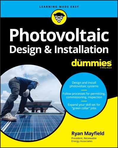
Ground-mounted racking systems, like the one shown in Figure 16-2, are often identical to tilt-up racking systems except in how the racks are held down. In ground-mounted systems, either concrete-encased poles or ground screws are common (more on these methods in “Supporting Ground and Top-of-Pole Mounting” later in this chapter). However, some racking manufacturers allow you to support the rails from the bottom up with a system known as bottom-up rails. With bottom-up rails, the rail sections have predrilled holes that match up to the holes on the bottoms of the module frames. To secure the modules on the rack, you just use a nut and bolt assembly. In racks that have plenty of access on the backside of the array, the bottom-up system may be preferable to top-down mounting so that you don’t have to set up ladders or scaffolding to access the front sides of the modules.
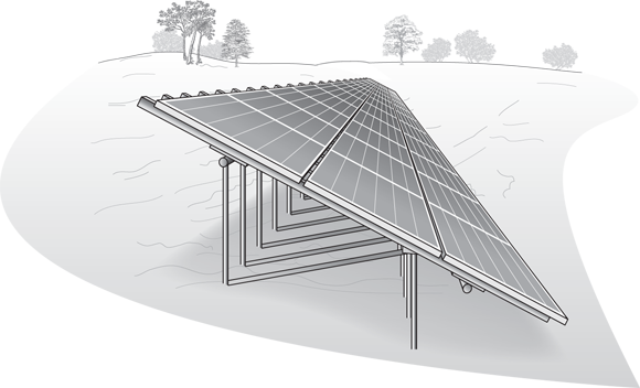
FIGURE 16-2: Ground mounting.
Though ground-mounted PV systems have many advantages, they aren’t without their issues. You need to keep the following in mind when working with this mounting option:
- The footings: Most people are more comfortable digging in the ground than drilling holes over where people sleep at night, but you still need to dig those holes correctly. I go though the major considerations regarding ground-mounted array footings later in this chapter.
- The required ground work: Besides the footings, you have to do a fair amount of ground work for the electrical portion of the job. Specifically, you have to dig a trench from the array location to the inverter and main distribution panel location. And because you’re burying electrical wires, that wire run and all the components you use must comply with the National Electrical Code® (NEC®).
- The accessibility of the modules: One last consideration is the accessibility of the modules to anyone who wants to approach the system. Here’s why you need to think about this point:
- The NEC® has rules you must follow for any wiring on PV systems that’s considered readily accessible. The NEC® makes you keep any exposed wiring and connectors out of the reach of unqualified people to protect those who may not realize what dangers they’re exposing themselves to because they didn’t read Chapter 13 of a certain PV design and installation book with a pretty black and yellow cover. As far as the NEC® is concerned, the easiest way to meet this requirement is to make the wiring and connectors not readily accessible. You can do this by fencing in the array, placing all the wiring and conduit in raceways, or raising up the system so the wiring and connectors are no less than 8 feet from the ground. Each one of these solutions has its own set of challenges, so I can’t give you one easy answer. On the positive side, racking manufacturers have been developing solutions to use in conjunction with their systems to aid PV installers in solving the problem of meeting this NEC® regulation.
- You don’t want thieves to be able to walk away with the array. PV modules are valuable items, and some ill-intentioned folks have caught on to that. If you place an array in a location where anyone can get to it, you and your client should at least consider installing some basic antitheft devices. These can be as simple as specialty hardware that requires specialized tools to remove or as elaborate as camera systems and alarms. I personally like the idea of fences with locked gates; this option solves the NEC® problem (see the preceding bullet) and helps deter potential thieves.
Top-of-pole mounting
The most iconic (at least in my mind) PV mounting system is the top-of-pole array. Arrays mounted on the tops of poles have been used for many years now; they’re best for any PV system (grid-direct or battery-based) and can be relatively simplistic in design and application.
In top-of-pole systems, a hole is dug in the ground based on the wind loading, soil type, and array size. The pole is then set in this hole and surrounded by concrete. The racking system itself is a bottom-up system (described in the preceding section), which means you can set up scaffolding underneath the array location and have full access to the bottom of the array. Figure 16-3 shows a typical top-of-pole racking system.
FIGURE 16-3: Top-of-pole mounting.
As with ground-mounted systems, top-of-pole arrays operate at cooler temperatures, allowing for increased power levels. In addition, top-of-pole arrays give you complete freedom in determining the array tilt and orientation. Why? Because the racking system is connected to the pole at a single spot, which means you can point the array in any direction and pick (or even seasonally adjust) the array tilt to increase the array’s energy yield.
 Top-of-pole arrays also open up the possibility of using a tracking system. Tracking PV arrays have the ability to track the sun from east to west each day and make small adjustments daily to account for the changes in the sun’s altitude angle. Tracking systems can help increase the overall energy output of an array, but they do introduce a moving part into your PV array where there wasn’t one before. So deciding whether or not to include a tracker requires some analysis on your part.
PV arrays mounted atop poles require a fair amount of ground work that includes setting the pole and trenching the conductors (wires) back to the rest of the power system. They also require you to find a way to safely elevate yourself when installing them. The easiest way is to use scaffolding set up around the base of the pole. The scaffolding allows you to move freely beneath the array and provides you with full access to the racking system.
When shopping for top-of-pole mounts, be aware that your options may be limited by the overall square footage of PV modules that can be installed on a single pole. The exact power rating of an array mounted on a single pole varies with your PV module selection, but the maximum size is approximately 3.6 kW for any one pole. This value means that you must either install multiple poles or investigate other mounting solutions if you’re working with larger arrays. If you’re installing multiple pole mounts, be sure to accurately account for shading between the two poles. After all, it can be quite frustrating to take the time required to install two or more pole mounts only to see one shading another.
As for mounting the PV array, the same rules that apply to ground mounting also apply for top-of-pole mounts, at least in terms of conductor and connector accessibility. Although with pole mounts, raising the modules above the 8-foot mark to make them inaccessible (in the eyes of the NEC®, anyway) can be easier.
Another consideration to make in terms of the pole and array height is the amount of snow received at the site. When calculating the array height, keep in mind that if any snow accumulates on the array, as soon as the sun comes out, the dark PV modules will warm up, and the snow will begin to slide off. This means that you need to have the bottom edge of the array high enough above the ground so the snow can slide off completely. If you don’t, the snow will build up and block the PV array’s solar access, causing energy production to be greatly reduced or even eliminated and a lot of weight to be added to the bottom half of the array.
Building-integrated mounting
One type of PV mounting that gets a lot of attention is the one that incorporates the PV modules directly into the building materials (instead of simply placing the modules on top of a roof). This is known as building integrated photovoltaics (or BIPV for short). BIPV isn’t as popular as the other racking methods I mention earlier in this chapter, but it’s gaining more traction. BIPV can take many different forms and use any PV module technology (either crystalline or thin film; see Chapter 6 for details). Systems have been installed where the roofing material is a PV array and where the PV array was integrated into the curtain walls installed along the face of the building. Some of the most well-known BIPV products are those that are installed into either a new or existing roof, not necessarily replacing the roof but rather becoming part of the roof.
BIPV is best suited for new construction. Although it’s mainly used in grid-direct systems, it can also be used in battery-based systems. For residential applications, PV manufacturers are producing small modules that are intended for installation on roofs that’ll also use tile or concrete shingles. The modules are manufactured in the same dimensions as standard roofing products so they can be installed in the appropriate location and then surrounded by the traditional roofing tiles. (If you’re considering installing one of these products, you need to evaluate the wiring methods you’ll have to use and contact the manufacturer for specific installation requirements.) The end result is a roof that now produces electricity. Because the PV modules become part of the roofing system in building-integrated mounting, you can see why this is difficult to do if the roof already exists.
BIPV can also be used on flat commercial roofs that use a membrane roof. The manufacturer takes up to six individual modules (each module is approximately 15 inches wide by 16 feet long) and incorporates them into a large membrane sheet (which is made of the same material as the existing roof). These modules on the now-large (approximately 10 feet wide by 20 feet long) sheet are all wired together, leaving you with one very large module. These large sheets can then be placed on a flat roof and “welded” to the roof using standard roofing practices, thereby creating a lightweight PV array that’s fully integrated into the existing roof.
BIPV does have some downsides, as you can see from the following:
- Because BIPV isn’t as common as any of the racking systems used with traditional framed modules, a BIPV system can be more expensive. Part of that cost increase is due to the material itself. Another part of the added cost is the required coordination of different building trades. For example: If the array is part of the window glazing, you need to closely coordinate all the individuals responsible for each part of the installation.
- Because BIPV is part of the building, the PV array (usually, anyway) isn’t facing the optimum orientation. For a flat roof, for example, the PV array isn’t tilted up at all; you therefore have to accept system losses due to this lack of tilting. On top of those losses, you must also consider how dirty the array will become over time. Flat roofs aren’t clean locations, and even in very wet climates, they don’t get washed off very well. Have your client plan to monitor the array’s energy output and get up on the roof periodically to clean it.
Considering Loading When You Mount an Array on a Roof
Every time you want to attach a PV array to a structure, you need to look at the effect the array will have on the building as a whole. The last thing you want is for the building to fail because you didn’t consider the loading (the addition of weight to the roof) and the existing structure. The type and amount of loading depends on the roof-mounting system you choose to use and where the array is placed on the roof. For example, a flush-to-roof system that stays a few feet in from a roof’s edges will have greatly reduced wind loading effects compared to a tilt-up array mounted near the peak of a roof.
As a PV system designer and installer, you must follow various building codes while designing and installing any roof-mounted arrays. The sections that follow review those codes and some common loading calculations you need to perform when designing a PV system with a roof-mounted array. (Note: In the following sections, loads and loading don’t refer to the electrical loads discussed elsewhere in this book; instead, they refer to structural considerations.)
Following building codes
The jurisdiction (the city or county) you’re working in has a set of building codes that it uses as a guideline for how much weight can be placed on a roof. The basis for the building codes in most locations in the United States is the International Building Code (IBC). The IBC contains multiple references to the American Society of Civil Engineers’ (ASCE) publication titled Minimum Design Loads for Buildings and Other Structures (ASCE 7-05).
Just like jurisdictions can follow the NEC® as much as they want, the IBC is merely a guideline. Many jurisdictions have additional requirements beyond the requirements listed in the IBC. To find out the exact requirements where you’re working, talk with the inspectors and someone in the local building department’s permit office.
Accounting for additional dead load
Additional dead load is the weight of the PV modules and all the associated racking materials installed on the roof. For most homes built in the last 30 years, the addition of a PV system is well within the structural limitations required. However, if you’re dealing with homes built prior to the 1970s, as well as homes built in locations where building codes took a little longer to be adopted, you should enlist the help of a structural engineer to verify that the roof framing can support a PV array. (Note: Even in relatively old homes, you can often spend a little time adding the proper amount of support. My home was built in 1929, which meant it wasn’t ready for PV. I had to add some additional bracing to support the existing rafters, but doing so didn’t require any major efforts.) Finding a structural engineer familiar with PV systems is nice but not an absolute requirement. When it comes down to it, the structural engineer doesn’t care too much about what the equipment on the roof is; she just wants to make sure all the loads are accounted for. You can generally find some good engineers to work with by asking some of the local general contractors who they use regularly.
When you look solely at the additional dead load of a PV system, the weight is generally close to 3 to 4 pounds per square foot. As long as this dead load value (which is the overall array and racking weight divided by the square footage of the array) is less than 5 pounds per square foot, you’re okay. Under normal conditions, this amount of weight is so far below the requirements for modern building codes that it rarely causes any issues.
Here’s an interesting fact to keep in mind: The 3-to-4-pounds-per-square-foot weight is less than the weight associated with adding a second layer of composition asphalt shingles, which is a standard allowance in roof load calculations. So if your client’s roofing material is one that allows for multiple layers (like composition asphalt) and there’s just a single layer of roofing material present, then adding a PV array will be less of a load than another layer of shingles. In other words, you should be just fine.
In addition, by placing a PV array on the roof of a home, you’re removing the areas where people can walk on the roof — a live load that all roof systems account for (I explain live loads in the next section). By removing the possibility of people walking on the roof (at least in the section where the PV array is), you can exchange the new dead load for that live load consideration. Doing so allows you to install flush-to-roof-mounted PV arrays on roofs that may not have allowances for the addition of future roofing materials on top of existing ones. (Note that ballasted and tilt-up racking systems still need additional considerations due to the added weight and wind loading.)
Although the overall additional dead load for a PV array is relatively small, the issue for many building departments is that you’re taking that distributed weight and transferring it to a few points, making the building handle additional point loading (transferring the weight of a distributed area to a single location). What many jurisdictions want to see is a minimum number of attachment points to help distribute the additional weight of a PV array over a number of roof-framing members. For flush-to-roof systems, the most common way jurisdictions calculate the minimum number of attachments required is to take the gross weight of the PV array (including the modules, racking, and any other material installed on the roof) and divide that by the number of proposed attachments. If the amount of weight per attachment exceeds a specific value (generally 45 pounds per attachment), the jurisdiction may require additional roof penetrations to help distribute the weight or an engineering review of the roof’s structural members. Ballasted and tilt-up racking systems need an engineering review anyway to make sure the point loading doesn’t exceed the roofing structure’s capabilities.
The numbers presented here work fairly well across the United States, but of course you can’t have a single answer for all places. Locations such as hurricane-prone Florida and earthquake-prone California may have additional requirements, which is why you need to talk with the city or county’s building department and make sure you design your system to its requirements.
Also, as soon as you start looking at installing a PV array on a commercial building, you can’t make any assumptions. During the design process, engineers commonly specify materials and methods that are code minimum, meaning there may not be any additional structural capabilities in the building to support a PV array. Consult with a structural engineer early in the process to verify whether the building can physically handle a PV array. I’ve been involved in projects where the sales process went too far before an engineer revealed that the building was below code requirements without any PV and that adding anything to the roof would be a disaster.
Looking at live loads
Any load that isn’t constant (like the weight of the array is) is considered a live load. Live-load specifications vary for every location and jurisdiction. Because you’re most concerned with record weather events, the live-load specifications may seem extreme for 99.9 percent of the time, but you need the array and building to stay put 100 percent of the time. In the following sections, I point out several live-load considerations you must make.
Wind loading
The amount of wind loading your array is exposed to is highly dependent on the array’s location. You can find a map of the United States in the IBC (Figure 1609 if you really want to look it up) that shows the basic wind speeds for use in designs; you can also visit www.windspeedbyzip.com for wind-speed data. The best way to find out the wind speeds in your client's location and make sure you use the exact numbers that the jurisdiction bases its calculation on is to ask the building department what it uses. The IBC uses multiple variables in defining the basic wind speed, including the characteristics of the surrounding terrain and the building height.
Your client’s exact wind loading is important to look at because it affects your choice of the appropriate array location and mounting method. If you want or need to place the client’s PV array close to the edge of a building, the array will likely need additional fastening to the roof (through extra penetrations or extra ballast material) due to the increased wind loading at the roof’s edge. The IBC helps you go through the calculations, but it doesn’t take you through them step by step. A great resource to walk you through the entire process is the February/March 2010 issue of SolarPro magazine, available for download at solarprofessional.com. If you still feel uncertain about the calculations, consult a structural engineer to verify the design.
Snow loading
Snow loading can be one of the most difficult live loads to predict and account for in your design. For flush-to-roof systems, the snow loading on a building should’ve been taken into account with the original building design; the addition of a PV array should therefore have little impact, meaning you don’t need to design for any additional snow loading when you’re dealing with a modern roof (one constructed within the past 30 years).
For rooftop arrays mounted with tilt-up racking, snow tends to drift and accumulate around the backs of modules (where they’re raised), creating increased point loading on the roof. This extra point loading can last for months in some locations — not a good thing. In addition to this drift, as snow accumulates on the tops of modules, it slides off the faces of the modules to the roof’s surface as soon as the sun comes out, creating even more point loading. With these systems, you need to work with a professional engineer to make sure the racking system and building will hold up during the times when the snowdrifts occur.
Because ballasted systems are also tilted up, they’re subject to the same snowdrift problems. However, these systems may pose even more problems due to the extra weight holding the array down to begin with. Not to beat a dead horse, but this situation is where a structural engineer earns her keep.
For all PV systems, you should also think about where the snow is going to go when it begins to melt. Snow-covered PV arrays still heat up very quickly, which means all that snow can slide right off them in a flash, posing a risk to anyone standing below the modules. If you’re installing a PV array in a snowy area, try to keep the array away from the edge of the roof, or install snow guards to reduce the risk of personal injury due to falling snow chunks.
Seismic loading
Section 1613 of the IBC insists you account for seismic loading, which is the pressure exerted on an array during an earthquake. Any racking system that has a positive attachment method (one that penetrates the roof), such as flush-to-roof mounting and tilt-up mounting, generally meets these requirements. If you’re using a ballasted racking system, you may need to address additional considerations as required by the local jurisdiction and the IBC.
Properly Attaching an Array to a Roof
Whenever you’re going to attach a PV array to a roof, you need to make sure that the attachment method is appropriate, that it’ll hold correctly, and that you aren’t allowing water to enter the building. In the next sections, I introduce you to the hardware used for making the connection and the options available to you for proper weather sealing.
Making attachments with lag screws
Attaching flush-to-roof and tilt-up racking requires you to penetrate your client’s roof — in other words, you have to drill holes; there’s no way around it (unless of course you opt for a ballasted racking, as described earlier in this chapter). The most common way of attaching either type of racking to a roof is with a lag screw that’s connected directly to a roof-framing member, which is either an engineered truss or a roof rafter.
Another very common method for attaching a lag screw is to get inside the attic space and attach a 2-x-4 or 2-x-6 wood block between two of the roof-framing members at the location where you want to make the roof penetration. This technique lets you create roof penetrations at the exact location you want, regardless of the roof-framing location. Another benefit is that the point loading you’re creating on the roof system is now being distributed to two rafters or trusses rather than just one. This second method is preferable because its added strength allows you to avoid the roof framing.
The exact dimensions of a lag screw are often determined for you based on the racking manufacturer’s requirements and the wind loading considerations for your client’s location (I cover wind loading earlier in this chapter). However, this fact doesn’t mean you shouldn’t verify the lag screw’s ability to keep the racking system attached to the roof. Lag screws are characterized by their pullout strength in various types of wood by the number of pounds per embedded inch they can withstand. For example, a ![]() -inch lag screw (a common diameter for roof penetrations) has a pullout strength of 266 pounds per inch in Douglas fir. Because you usually won’t know what the exact type of wood a client’s roof is made of, I suggest you assume a wood type of spruce/pine/fir. This wood type has the lowest pullout strength (205 pounds per inch for a
-inch lag screw (a common diameter for roof penetrations) has a pullout strength of 266 pounds per inch in Douglas fir. Because you usually won’t know what the exact type of wood a client’s roof is made of, I suggest you assume a wood type of spruce/pine/fir. This wood type has the lowest pullout strength (205 pounds per inch for a ![]() -inch lag screw) in order to cover all possibilities. You may be required to produce this information for the local jurisdiction, so be sure to have an idea of the pullout strength ahead of time.
-inch lag screw) in order to cover all possibilities. You may be required to produce this information for the local jurisdiction, so be sure to have an idea of the pullout strength ahead of time.
When installing lag screws, you first need to drill a pilot hole that’s 60 to 75 percent of the lag screw’s diameter. Because the lag screw will follow the path your pilot hole drills, make sure the hole is perpendicular to the roof framing by using a rafter angle square (also known as a Speed Square) beside your drill. If the pilot hole isn’t square, the lag screw won’t be able to set fully, and the roof penetration may begin to leak after a few years.
If required by the local jurisdiction, you can determine the maximum uplift force that’ll be imposed on the array with the help of calculations outlined in ASCE 7-05. Using the tables in ASCE 7-05, you can determine the minimum required lag screw length. Keep in mind, though, that the lag screw has some materials to get through before it actually reaches the roofing member, and the tables are based on the lag screw being embedded into that wood. Take into account the depth of the footing that the lag screw is going through, the roofing material, and the plywood roof decking material when calculating the overall lag screw length.
The calculations to determine the lag screw depth and footing spacing are most critical for systems that use tilt-up racking that exposes the array to much greater wind loading. Unfortunately, the calculations and all the considerations are beyond the scope of what I can present here, so I suggest either teaming up with a structural engineer or doing more research on this subject by examining the following sources:
- International Building Code
- The North American Board of Certified Energy Practitioners (NABCEP)’s study guide for Certified PV Installers
- SolarPro magazine, specifically the February/March 2010 issue
Sealing roof penetrations with flashing
Recently, the methods used for sealing roof penetrations have come to the front of the PV industry’s collective mind. Why? Because the majority of construction-related litigation in the United States is based on water intrusion. Given that many business can’t survive a major lawsuit, performing due diligence on your sealing methods during every system installation can only serve you well in the long run.
I know a lot of PV pros out there have used nothing more than aluminum L feet (a piece of aluminum that looks like an L and measures about 3 inches in width and height) screwed directly on top of the roofing material with just enough roof caulking in between the two to keep the water out (even I’m guilty of installing numerous systems like this). I also know that a number of installers who use this method don’t see the need to change their methods now. Fortunately, you can get off to a good start with the knowledge of how to seal a roof penetration the right way.
One very specific IBC requirement you should be aware of is 1503.2, which requires that flashing be installed around roof penetrations in order to keep moisture out of the building. What’s flashing, you ask? It’s a physical barrier that extends past any roof penetration to keep water from reaching the hole in the roof. Figure 16-4 shows you a couple examples of flashing.

FIGURE 16-4: Different types of flashing.
To meet the IBC code requirement of flashing all roof penetrations, you need to use either a post-type footing (which is provided by the racking manufacturer) or a block-type mount with integrated flashing (which comes from either the racking manufacturer or an independent third-party company). I describe these types of flashing in more detail in the following sections.
Post-type footings
The post-type of roof penetration, shown in Figure 16-4a, is a great flashing option, especially when you’re installing a PV array on a brand-new roof or on a building that’s getting reroofed. It’s ideal for these scenarios because you can set the posts down on the roof before the roofers come in and start their work (or in the case of a reroof, after the original roof has been removed and before the new one starts to go down). When the roofers show up, they can seal the roof as they normally would; they just have to work around a bunch of posts. These posts are sealed the same as any other roof penetration the roofers deal with every day, so they shouldn’t be new to the roofers.
For the best results, coordinate the placement of post-type footings with the roofer beforehand. The last thing you need to do is surprise the roofing crew one morning with a roof full of posts that it wasn’t expecting. Trust me, you don’t want to wind up on any roofer’s bad list. In fact, why not partner up with a good roofer for all of your roof penetrations? Roofers are much more knowledgeable about proper roofing techniques and materials, and the roofer’s job will be easier and higher quality in the end, so the relationship will be mutually beneficial.
You can install post-type footing on an existing roof for use with either flush-to-roof or tilt-up racking systems, but this is more difficult and typically requires you to cut into the existing roofing material for each post. Doing so is very time-consuming when you’re up there on a hot (or cold) roof.
Block-type mounts with integrated flashing
The block-type mount, or flashed penetration, shown in Figure 16-4b is another option for flush-to-roof and tilt-up racking systems. It’s good for use in new construction or on existing roofs, and you can find a number of different options available for just about every roofing material used today.
Block-type mounts with integrated flashing are constructed with a mounting block attached to the top of the flashing material to prevent water from penetrating the flashing. To install this flashing on a roof, take the flashing and slide it up underneath the existing roofing material so that the top part of the flashing is under the two rows or shingles directly above the roof penetration, keeping water from reaching the hole in the roof. You can then mark the hole location and drill a hole in that spot. Place a small amount of roofing caulking to seal the hole you drilled and insert a lag screw through the integrated block (be sure to tighten it into the roof-framing member). Your first few block-type mounts may take some time to get the hang of, but before your first row of footings is set, you’ll have the process down. A great tool to invest in is a roofing pry bar, which helps you set the flashings properly without tearing the roof apart in the process.
Different variations of this flashed penetration are available for nearly every type of roof covering (composition asphalt, wood shake, and tiles). They’re all more expensive initially than simply attaching an L foot directly to the roof deck, but I consider them cheap insurance against bigger problems and the proper way to make the connection as defined by building codes.
Supporting Ground and Top-of-Pole Mounting
For PV arrays atop ground and top-of-pole mounts, you need to think about how you’re going to secure the racking system into the ground. Often you can work directly with the racking manufacturer to help determine the specifications for the foundations. Many of them have engineered their systems and can share that information with you. They’re generally willing to dictate the diameter and depth of the hole(s), as well as the required spacing for ground-mount systems. (Spacing considerations need your attention only when multiple poles are going in the same area. Top-of-pole mounts use just a single pole.)
For locations that have difficult soil conditions (such as bedrock close to the surface or very sandy soil), or if you want to raise the array higher than standard heights, you may need to have a geotechnical engineer evaluate the design to determine whether any additional reinforcements are needed. I suggest you find someone who’s familiar with the local conditions by searching the Yellow Pages or talking with general contractors in the area.
The most common material used for the vertical pole support is steel tubing. The sizes range from 2 inches all the way to 8 inches in diameter, depending on the exact racking method.
When installing ground-mounted systems, site preparation is vital. The reason ground mounts need extra attention over top-of-pole mounts is that without the proper preparation, a ground-mounted array can quickly become cockeyed during installation. Even a small 1⁄8-inch deviation in the beginning can have huge effects just 50 feet down the line. The most accurate way to prepare the site for a ground-mounted system is to spend some time with a surveyor’s transit and leveling tool. Doing so helps you mark the coordinates for all the footings you need to install and ensure that they’re in a straight line.
You have two options for securing the posts into the ground via the footing:
- Historically, the most common method is to dig an appropriately sized hole, place the pipe in the hole, and fill in the remainder with concrete. This is a very effective and secure method, but it can be rather labor intensive. In order to do it right, you need to place the pole in the ground accurately and then secure the pipe in a vertical position so that when you pour the concrete, the pipes stay in place. (For detailed top-of-pole installation steps, check out issues 108 and 109 of Home Power magazine, available at
homepower.com.) - Another method that’s gaining popularity is the use of helical piers. These systems essentially drill the pipe into the ground. The pipes have blades along their bottoms that make them look like a very large screw. They’re screwed into the ground with the help of a tractorlike vehicle that has a special attachment installed for drilling the piers into the ground. These systems don’t require any digging or concrete, but they do call for specialized equipment and expertise if you want to install the piers accurately. (Note: At this time, helical-pier systems are limited to ground mounts because the piers aren’t large enough for most top-of-pole installations.)