Chapter 8
Keeping Current and Voltage in Check: Charge Controllers
IN THIS CHAPTER
![]() Looking at basic charge controller functions
Looking at basic charge controller functions
![]() Scoping out the two main controller types: MPPT and PWM
Scoping out the two main controller types: MPPT and PWM
![]() Selecting the option that meets your client’s needs
Selecting the option that meets your client’s needs
The process of naming equipment in the PV world (and the electrical world in general) can be classified as unimaginative at best. This is unfortunate in the sense that the components don’t sound like some space-age, whiz-bang item. But it’s actually fortunate in that the names are generally very descriptive, allowing you to determine an item’s function quickly.
Charge controllers are a prime example. When introducing charge controllers in my classes, I always give my students one guess to name their primary function. Needless to say they always guess “to control charging.” Even though you may not know exactly what charge is being controlled from the name of the item, you immediately get a sense that charge controllers are somehow manipulating the current coming from a power source.
The charge controllers that are commercially available come in a variety of sizes and have an assortment of features. Small charge controllers can be used in very small systems with one or two PV modules charging a small battery bank. Larger charge controllers are designed for use with multiple-kilowatt arrays and large battery banks.
In this chapter, I tell you all about the main functions, special features, and types of charge controllers. I also explain how to specify (select) a controller for the particular system you’re designing.
The Essentials of Charge Controllers
Simply stated, in order to properly maintain a battery bank that’s being recharged by a PV array, you must include a charge controller in the system design. In the sections that follow, I introduce the basic functions of a charge controller and describe the features offered on some models.
Seeing how a charge controller works in stages
 A charge controller’s main role in a PV system is to properly control the charge from the PV array into the battery bank by controlling the current and voltage from the array into the batteries. Without a charge controller, like the ones pictured in Figure 8-1, the PV array would be able to send all of its current into the battery bank without any regard for the batteries’ needs. The batteries, in turn, would become overcharged and eventually ruined.

FIGURE 8-1: Some examples of charge controllers.
Charge controllers regulate the voltage and current sent to the batteries during the charging process. Each charge controller has multiple stages for which it regulates different voltage and current levels; in Figure 8-2, you can see three such stages. This figure shows how both the voltage and current vary over time based on the charge set-points, which are the voltage levels that you want to charge the batteries to; each battery manufacturer publishes its own charge set-points that you should use if you want to maximize the batteries’ life span. (Note: During the installation process and before commissioning the system, you must adjust the charge set-points as necessary.)
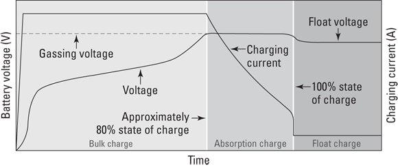
FIGURE 8-2: Three-stage charging for a charge controller.
In the following sections, I describe a charge controller’s role during the three charging stages.
Bulk charging
The first charging stage is bulk charging. It happens first thing in the morning after the batteries’ voltage and capacity have been drained down since the sun set the previous day. Bulk charging pushes as many amps as possible back into the battery bank from the PV array and gets the voltage up in the process.
 To better understand bulk charging, it may help to equate it with trying to fill a large glass of water from your faucet. The voltage is the water level in the glass. If the voltage in the battery (or the water level in the glass) is relatively low, then you need to allow as much current from the PV array as possible into the battery (in other words, you need to open that faucet all the way). In this analogy, the charge controller is the faucet that controls how much water (current) can flow into the glass. Both the PV array and the faucet are limited in the flow they can provide to their respective containers, but as long as the level of energy (or water) in the container is low, the container (the battery or the glass) will gladly and readily accept the flow. As the current (or water) continues to flow, the battery voltage (the water level in the glass) continues to rise. This charging process continues until the battery voltage reaches a predetermined level known as the bulk voltage set-point. At this point, the current needs to slow down. If it doesn’t, the battery can’t effectively accept the charge, and the current becomes heat (or, in the case of the water glass, the water simply starts spilling over the edge).
The exact bulk voltage set-point is determined by the battery manufacturer. Some batteries are able to take a higher charging voltage than others, so you need to make sure your controller is set correctly for the batteries you’re using, as indicated in the owner’s manuals provided by the controller and battery manufacturers. The voltage is taken above this set-point on purpose during the equalization charge that I tell you about in Chapter 7; this is a deliberate act that requires monitoring and should only be done according to the manufacturer’s recommendations. If the batteries are consistently charged above the bulk voltage set-point, the overall life of the battery bank will be greatly reduced.
Absorption charging
The second charging stage in the three-stage charging process is absorption charging. After a battery bank has been brought up to the bulk voltage set-point (see the preceding section for more on this), it can’t really accept high levels of current. If it’s forced to, the end result will be heat generation and excessive gas production — not a good thing.
When a battery reaches its manufacturer’s bulk voltage set-point, it’s really only about 80-percent full. The point of the absorption charge is to top off the battery. Think about a glass of water under a faucet. If you stop the flow just before the water spills over the edge, when you turn the faucet off, the glass isn’t 100-percent full because the force of the water was pushing it over the top.
During the absorption-charging stage, the charge controller holds the battery voltage constant and reduces the amount of current sent into the battery bank. (It’s like reducing the flow from the faucet to top off the water level in the glass.) When this process is done, the bank is fully recharged.
Typically, a full battery-charging cycle (bulk and absorption) is a multiple-hour event; the exact length of time required depends on the size of the battery bank and the PV array. The charge controller automatically starts and stops the charging stages, but if the charging source is the PV array, there’s always the chance that the sun will disappear before the controller has the opportunity to finish its work. In this scenario, the battery bank doesn’t reach 100-percent capacity and needs an additional charging source, such as the utility grid or an engine generator, to help it get there.
Float charging
The final charging stage is float charging, and it’s designed to keep the battery in a full state of charge after the absorption-charging stage has topped off the battery bank. Typically, a PV array spends only a small amount of time float-charging the battery bank due to the limited number of hours it has each day to recharge the bank. A charge controller enters into a float-charging stage only after the first two charging stages have been completed and when there’s enough power from the array to send a float charge into the batteries.
When the number of peak sun hours is very limited (like during the winter), a PV array may not be able to get the battery bank to the float voltage at all because the lack of sun doesn’t allow for a full charging cycle and because the bank may be drained relatively low due to greater use. In the summer, an array may be able to recharge the battery bank in a short amount of time, allowing it to spend a fair portion of the day in the float-charging stage.
Surveying special effects provided by some charge controllers
Some of the small charge controllers used in PV systems have only one feature: the ability to regulate the charge entering the battery from the PV array. Others, like those designed to work with larger systems (greater than 500 W), may include a variety of additional features to complement the main battery-charging feature. The need for and use of these features, which I explain in the next sections, vary among PV systems, but all of these features are available in every type of charge controller.
Load control
In systems that support direct current (DC) loads (namely, stand-alone, battery-based systems, although DC loads can be supported anytime batteries are present), some charge controllers employ a load-control feature to make sure the batteries don’t become excessively discharged. This feature works by pulling electricity directly from the battery bank and sending it to the loads through the charge controller. As the loads continue to run, the battery bank’s capacity is reduced and monitored by the charge controller. If the loads run long enough, the charge controller senses the batteries’ reduced capacity and cuts off the flow to the loads, which ensures the connected loads don’t drain the batteries too low and cause them harm. The load-control feature doesn’t allow the loads to receive power again until the battery bank has been recharged to a certain point, eliminating the possibility of the loads being reconnected to the bank before sufficient capacity is restored in the batteries.
DC lighting loads are some of the most common devices used in conjunction with the load-control feature, although most any electrical appliance that can run off of DC electricity can be controlled.
Auxiliary load control
In certain situations, there may be a need (or desire) to run loads only when the battery bank is being charged excessively or when the battery bank is running low and needs attention. These auxiliary loads (additional loads on top of what the building is using) are used to enhance the safety or performance of the entire PV system. Fortunately, some charge controllers include relays that can close an electrical switch when the battery reaches a certain level and send power to an auxiliary load.
One common auxiliary load is a fan connected to a flooded battery bank’s enclosure. (I introduce flooded batteries in Chapter 7.) When the PV array (or other charging source) brings the battery voltage up to a certain charge level, the flooded batteries begin to release hydrogen gas. The auxiliary-load-control feature of a charge controller is activated when the batteries reach the predetermined voltage and power is sent to the fan (which in this case is the auxiliary load). Other auxiliary loads such as warning lights or alarms can be connected to warn your client about a battery’s excessive or reduced voltage levels.
Status meters
Some charge controllers feature status meters that can either be integrated into the face of the controller or be run remotely for a client to see in a convenient location (such as the kitchen or other living space). Status meters allow PV system owners to evaluate the battery and PV array voltage levels of their system with a quick glance.
Other, more sophisticated status meters also track the energy values into and out of the battery bank. These amp-hour meters are especially useful to owners of stand-alone, battery-based systems who rely on their battery banks for the majority of their power. By using a status meter that includes an amp-hour meter, your client can accurately know the status of her battery bank and know when she needs a secondary charging source, such as an engine generator, to bring the battery capacity back up. This level of monitoring is actually quite important for stand-alone systems because the batteries are the user’s main power source; as such, she should know their status at all times.
Maximum Power Point Tracking Technology
The technology that allows a PV array to deliver the maximum amount of energy to a battery bank is known as maximum power point tracking (MPPT). MPPT charge controllers gained popularity in the early 2000s when manufacturers released highly reliable and accurate versions that allowed users to maximize the charging ability of their PV array and, in some cases, reduce the required PV array size for battery charging compared to some of the older technology.
In the following sections, I explain the magic behind MPPT controllers and outline their pros and cons so you can evaluate whether this technology is the right solution for your clients.
Note: All commercially available grid-direct inverters also use MPPT technology; see Chapter 9 for an introduction to inverters.
How MPPT works
An MPPT charge controller uses the three charging stages presented earlier in this chapter to allow a PV array to operate at its maximum power point (abbreviated MPP) regardless of the voltage of the battery bank connected to the controller. Other charge controller technologies, such as pulse-width modulation (covered later in this chapter), can’t fully use a PV array’s MPP.
In Chapter 6, I explain that the MPP is defined as the point on the IV curve where the current multiplied by the voltage yields the highest power value. (In other words, it’s the product of the maximum power voltage, Vmp, and the maximum power current, or Imp.) For a typical 12 V nominal panel, the voltage associated with the MPP is somewhere around 17 V. PV manufacturers realized early on that this was the voltage value required to effectively charge a 12 V nominal battery bank in nearly all worldwide geographic locations. (Keep in mind that module voltage decreases when the module temperature rises, so the extra voltage is necessary to push the electrons into the battery bank when the module’s temperature is elevated.)
The maximum power voltage of 17 V doesn’t always equate directly to the required voltage needed to charge a battery bank, though. Depending on the technology and the charge set-point, the voltage necessary for charging a 12 V nominal battery bank can range anywhere from 13 V to 15 V. Therefore, a PV module can produce more voltage than a battery bank can fully use. Enter the MPPT controller.
MPPT controllers take the power from a PV array at the MPP, regardless of the required battery voltage, and deliver that same amount of power (minus efficiency losses, of course) to the battery bank because they’re able to reduce the voltage from the array to the battery’s required level. And because power is the product of voltage and current, if the voltage is decreased, the current is increased in order to keep the same power level. MPPT controllers boost current into the battery bank in relation to the current received from the array.
I think this concept is best illustrated in Figure 8-3, which depicts the power curve for a typical 12 V nominal PV module. The peak of the curve represents the maximum power value, which is the level that the PV module can produce. The graph also shows the location of a typical battery charge set-point. If you move straight over to the right from that point, you’ll see the power level associated at the battery-charging voltage. The difference in the MPP and the power level associated with the battery-charging voltage represents the increased power output due to the use of the MPPT technology. The PV array’s power levels move throughout the day depending on the environmental conditions, and MPPT controllers adjust right along with them.

FIGURE 8-3: The power gained through the use of MPPT controllers.
The pros and cons of MPPT controllers
MPPT controllers have become the most popular charge controllers for larger battery-based PV systems (both stand-alone and utility-interactive) thanks to their ability to fully use the power produced by a PV array. Another good thing MPPTs have going for them is their ability to take a PV array wired for a higher voltage and still charge a low-voltage battery bank. For example, with the help of an MPPT controller, you can take a PV array that’s wired in a series configuration up to 150VDC and still charge a battery bank all the way down at 12 V nominal. Having a higher-voltage array allows your client to locate the PV array farther from the battery bank and not have to take out a second mortgage for the length of wire connecting the two. Finally, MPPT manufacturers are constantly adding features and increasing efficiencies. These improvements help you, the designer and installer, by increasing the flexibility in your design.
 A major drawback to MPPT controllers is the cost. This technology comes at a price (about $800 for a standard unit as of early 2010). Justifying the extra expense for very small systems that don’t fully realize all the benefits can be difficult, which is why MPPT controllers are often used only in larger arrays.
Pulse-Width Modulation Technology
Although not as sleek and sophisticated as MPPT (which I fill you in on earlier in this chapter), pulse-width modulation (PWM) charge controllers are very effective in charging battery banks and will likely be a popular technology used in PV systems for years to come. In the sections that follow, I describe the workings of PWM technology and note the pros and cons of using it so you can decide what’s best for your clients.
How PWM works
Just like MPPT controllers, PWM controllers regulate battery charging via multiple set-points. However, unlike MPPT controllers, PWM controllers can only use the voltage from the array that equals the voltage required by the batteries. (For example, if the battery bank needs 14 V to charge and the array can supply 17 V, the controller can only accept the 14 V.) This characteristic inherently reduces the overall power available from the PV array because the battery-charging voltage rarely matches the array’s maximum power voltage. Because the battery bank dictates the voltage, the amount of current sent into the battery from the array is also limited (so the current value from the array that’s associated with the battery-charging voltage is different from the maximum power point current).
As the battery bank gets full, the PWM controller regulates the charge into it by pulsing the charge (turning the power on and off) from the array into the bank many times each second. Because the pulsing of the power happens so fast, the batteries “see” the current flow from the array as a slowly declining line, as shown in the graph. This pulsing of the current, where the controller starts and stops the current flow for various amounts of time, allows the battery to accept the charge and become fully recharged.
I like to think of the way a PWM controller works as standing with your hand on a water faucet and rapidly turning the water on and off as your glass begins to fill up. By stopping the flow for brief periods, the glass can accept all the water coming into it without losing any of it.
The pros and cons of PWM controllers
PWM controllers may not be as technologically advanced as MPPT controllers, but they’re a proven technology that works well in many applications because they can be used with all battery technologies — even with small PV systems that have just a few PV modules charging a few batteries. Also, they’re a lower-cost option compared to MPPT controllers, and they come in sizes to match very small PV applications (of course, they can also support multiple-kilowatt installations). They can even serve as effective load controllers for wind and microhydroelectric systems if your client needs that.
The main drawback of PWM controllers? Because they aren’t as efficient as MPPT controllers in transferring the power generated by a PV array into a battery bank, you may need more PV modules in an array to get the same charge as you’d get with the help of an MPPT controller — a fact that ultimately costs your client more money.
Specifying a Charge Controller
When it comes time to specify the charge controller in a client’s system, you need to look at the system as a whole and how the charge controller will fit into it. Chapter 12 outlines the methods used to size a charge controller based on the system design and electrical requirements in relation to both the PV array and the battery bank.
Make sure you always consider the voltage and current values during the charge controller selection process. As I note earlier in this chapter, MPPT and PWM controllers come in a variety of sizes. Each size of controller is rated according to its maximum and minimum voltage levels, but the current level a controller can handle is actually the more critical specification. Every charge controller is limited in the amount of current it can process due to its type (MPPT or PWM) and size (small or large). Consequently, you need to evaluate the amount of current the PV array will produce to specify the correct charge controller for your client.
If the controller needs only to handle the battery charging and maybe control a single load, a basic PWM charge controller should suffice. However, if the application requires advanced metering and the ability to run auxiliary loads, a more advanced MPPT controller is generally your best bet (although you may also need to suggest multiple MPPT controllers to efficiently address the client’s needs).