Chapter 17
Integrating the Electrical Elements
IN THIS CHAPTER
![]() Placing electrical equipment in the right spots
Placing electrical equipment in the right spots
![]() Reviewing some wiring basics
Reviewing some wiring basics
![]() Examining the two components of grounding
Examining the two components of grounding
![]() Connecting to the grid
Connecting to the grid
After you analyze your client’s site, specify the equipment needed for either a grid-direct or battery-based system, size all the components, and assemble the mechanical parts (as I explain in Chapter 16), you need to install the electrical elements of the system safely and according to National Electrical Code® (NEC®) requirements. To do so, you have to know Code references as they pertain to PV systems specifically and electrical systems generally.
The electrical portion of PV installations tends to be highly scrutinized by inspectors and Code officials (such as plan reviewers in the building department) reviewing projects. In addition, many inspectors have now seen enough PV systems to know what to look for and can identify problem spots (see Chapter 18 for the full scoop on the inspection process).
In this chapter, I dive into some Code-related topics to know during your installations. I cover equipment locations, wiring, grounding considerations, and the requirements you’re responsible for when connecting to the utility.
Location Is Everything: Knowing Where to Place Electrical Equipment
As you install a PV system, you’re bound to find a number of potential places to locate the (many!) different pieces of electrical equipment. Your charge is to evaluate the different possible locations and decide on the best spot. This spot must be compliant with the NEC®, adhere to the manufacturers’ requirements, and make sense for the system owner and his situation. The following sections focus on the Code requirements for the electrical equipment locations, specifically making sure the equipment is properly rated and grouped together to allow for maintenance and emergency shutdown.
 You must evaluate the site-specific requirements on a per-job basis.
Manufacturers’ requirements for equipment locations
A statement found early in the NEC® — Article 110.3(B), to be exact — mandates that all equipment must be installed and used in accordance with any instructions for that equipment. Consequently, to be compliant with the Code, you must install all electrical equipment according to the various manufacturers’ instructions. So if the installation manual says you can install the equipment only on even-numbered days and you install it on an odd-numbered day, you’re in violation of the Code. Granted, that’s a silly example, but it illustrates the importance of knowing a manufacturer’s requirements. I’ve seen installations that failed inspection because the inverters weren’t spaced properly according to manufacturer instructions; in each case, the inspector demanded that the misplaced inverters be moved.
Avoid placing any electrical equipment in direct sunlight (with the exception of the PV modules, of course; I explain how to install the modules in Chapter 16). For the inverters, this is good practice because an inverter’s ability to produce power is reduced as it grows hotter. Equipment such as overcurrent protection devices (OCPDs) are also affected by increased temperatures (you may need to derate them per the manufacturer’s instructions if the temperatures get too high). Other equipment, such as disconnects and combiner boxes (boxes that place all the PV strings in parallel), may not normally be negatively affected by high temperatures, but when in direct sunlight for multiple hours each day, the labels you use on them may degrade with time and be difficult to read. For conduit runs, you may not be able to avoid locations in direct sunlight. If this is the case, make sure the conduit is properly rated for outdoor installation by referring to the manufacturer’s spec sheet.
Any electrical component you install with electrical terminations inside of it can be called an enclosure (some examples include disconnects, combiner boxes, and inverters). Make sure you know the National Electrical Manufacturers Association (NEMA) enclosure ratings before installing any electrical equipment in a PV system because the NEMA rating of the enclosures you install affects where the equipment can be installed. The most commonly seen NEMA enclosure ratings for PV equipment are
- NEMA 1, indoor installations only: This enclosure offers no protection from dust or water entry. (Nearly every battery-based inverter is rated NEMA 1 — in fact, I can’t think of any exceptions.)
-
NEMA 3R, outdoor installation, typically on a vertical surface only: This enclosure type offers protection from falling rain. (Most grid-direct inverters — but not all — have at least a NEMA 3R rating.)
 The reason I specify vertical surfaces for NEMA 3R enclosures is due to the listing process. When manufacturers have their equipment tested, the standard for NEMA 3R is that the equipment is mounted on a vertical wall. Therefore, unless specifically stated otherwise, you can install enclosures rated at NEMA 3R only in the vertical position. It can be tempting to install a NEMA 3R enclosure on a roof at the same angle as the roof (I’ve even seen this done), but the problem is that the enclosure wasn’t designed for that application. If installed on the same angle as the roof, it may not be able to properly protect the electrical connections inside from rain and ice.
 - NEMA 4, outdoor installations on horizontal or vertical surfaces: These enclosures can withstand direct spray from a hose and splashing water.
Locations for disconnecting means
When I refer to disconnecting means, I mean that, in the most generic sense, you need to install disconnects such that when you go to work on an inverter, you can safely disconnect both the AC and DC sides of the inverter from all sources of power with approved methods at the inverter location.
The NEC® requires the PV disconnecting means be installed in a readily accessible location, either on the outside of the building or after it enters the building, at the nearest point of entry. But placing the disconnecting means properly can be a difficult task within most PV systems because many PV output circuits (which run from the combiner box to the DC disconnect) enter a building up at the roof location, and no “readily accessible” location exists up there for placing a disconnect either inside or outside of the building. Thankfully, an exception applies to this Code section that refers you to Article 690.31(E). It allows you to install the PV source circuit or PV output circuit inside a building without first installing a disconnect so long as the conductors (wires) are inside metallic conduit until they reach the disconnect.
 Most grid-direct inverter manufacturers now include a disconnect switch that can be integrated into their inverters, allowing you to disconnect the DC power source right at the inverter (and sometimes even the AC power source with the same switch). These disconnects are a separate piece that mates to the inverter during installation. The inverter can then be removed safely, leaving the disconnect on the wall and allowing for the installation of a new inverter. (See Chapter 10 for more on disconnects integrated into inverters.)
Many inverters that include an integrated disconnect make provisions for the installer to also use the disconnect as a combiner box. This means you can bring down multiple PV source circuits from the roof to the combiner/disconnect and place them all in parallel at the inverter location. In fact, the 2011 version of the NEC® will require a disconnecting means at the point of PV source circuits placed in parallel. Using the integrated combiner/disconnects from the manufacturer can help you easily meet this requirement.
For those inverters that don’t have an integrated disconnect, you need to install AC and DC disconnects at the inverter location. This process involves mounting at least one disconnect next to the inverter to disconnect the PV source circuits. If the inverter is installed at the main distribution panel (MDP), the circuit breaker used to make the connection to the utility can serve as the AC disconnecting means. If, however, the inverter is mounted at a location other than the MDP, you must install an additional AC disconnect at the inverter location. If the inverter and AC disconnect happen to be located at the utility meter location, you may satisfy both the NEC®’s and the utility’s requirements for disconnects with the same disconnect (you find out more details about utility disconnects later in this chapter).
The NEC® also says that a disconnect “shall not be required at the PV array location,” which means that for ground- and pole-mounted arrays (see Chapter 16), you can run PV source circuits without installing a disconnect at the array. However, most PV installers consider it a best practice to install a disconnect there because doing so provides you with an easy place to disconnect the PV circuits. (Besides, when the 2011 version of the NEC® is available, you’ll need a disconnect if you combine the circuits at the array.)
Combiner boxes and junction boxes and wiring, oh my!
Making the transition from module conductors in free air to the conductors you run through the client’s building (or underground) to the disconnecting means has to happen in some sort of enclosure, either a combiner box or a junction box. (A junction box is an enclosure that looks very similar to a combiner box on the outside. Inside, it uses terminals to transition the PV source circuit wires [USE-2 or PV wire; see Chapter 10] to the building wiring [THWN-2]. These terminals don’t place any conductors in parallel though, so you have the same number of conductors entering and leaving the junction box.) This enclosure typically lives at the array location, thereby reducing the length the exposed conductors have to run.
Until your client’s jurisdiction is using the 2011 version of the NEC®, you don’t have to have a disconnecting means adjacent to a combiner box. So if you want, you can install a combiner box at the array location and bring a single PV output circuit down to the inverter. Generally, however, running the individual strings to the inverter and using a combiner box at the inverter location is considered a safer method. If that’s the method you choose to use, then you must still incorporate a junction box at the array location to transition the outdoor wiring to indoor wiring that you can run in conduit.
Make sure the junction or combiner box you choose has the proper NEMA ratings for the environment you install it in (see the earlier section titled “Manufacturers’ requirements for equipment locations” for details). Also, you may need to consider the heat effects on the fuses if you decide to mount a combiner box on a rooftop or in a location where the temperatures will be greater than the manufacturers’ ratings (see Chapter 13 for more on this).
Working on Wiring
The actual act of wiring up a PV system isn’t all that complicated if you’ve taken the time to plan for and set up your installation. Of course, this doesn’t mean the process is without its own set of issues and difficulties. In the sections that follow, I point out some of the installation-specific details you need to keep in mind. (If you’re curious about the different types of conductors and conduit that are typically used in PV installations, head to Chapter 10; for the how-to on sizing conductors and conduit, see Chapter 13.)
Seeing red (and green and white): Color-coding
When it comes to wiring PV systems, one of the most common mistakes I’ve seen is someone mixing up the color of the conductors used. The NEC® has a very specific set of requirements for color-coding based on the function of the conductor in the circuit.
The NEC® requires the following color-coding for wiring in PV systems:
- Equipment-grounding conductors (EGC) must be green, green with yellow stripes, or bare wire.
- Grounded (or neutral) current-carrying conductors must be white or gray.
- Ungrounded (or hot) current-carrying conductors can be any color other than those mentioned for equipment-grounding and grounded conductors. However, the most common colors are black and red.
To help you remember what colors of conductor go where, think of the 120/240 VAC wiring system in your home. When you look at the wires coming into the outlets around your house, you have one black wire, one white wire, and one bare copper wire (which is sometimes green instead). The black wire is the one that’s connected to the circuit breaker in the MDP or subpanel, the white wire is connected to the neutral busbar, and the bare (or green) wire is connected to the ground busbar. (In that same MDP, the neutral busbar is connected directly to the ground busbar.)
If you look at a 240 VAC load, like your electric clothes dryer, you see a red wire in there too. In this case, the red wire and the black wire are connected to a two-pole circuit breaker. In this wiring scheme, the black and red wires are known as the ungrounded (or hot) current-carrying conductors, and the white wires are known as the grounded (or neutral) current-carrying conductors. The bare or green wires are the equipment-grounding conductors; they don’t carry current in properly installed and operating circuits.
So what does all of this mean to your PV system? As you well know, a PV module has two conductors on the back of it. As with all DC circuits, one side is positive (marked with a plus sign), and the other is negative (marked with a minus sign). Because DC electricity flows in a single direction (see Chapter 3 for more on DC electricity), the designation of the positive and negative sides, or polarity, is important to start with. Although all the PV module conductors are marked positive and negative, the best way to define the different parts of the PV circuits really isn’t with the terms positive, negative, and ground. This terminology isn’t incorrect, but you can do better. Most people associate red wires with the term positive and black wires with the term negative. When you install a PV system, you’re going to have a positive and a negative conductor, but one of those conductors will be connected to ground (just like the neutral conductor is in the MDP at your house).
If you can get yourself into the habit now, remove the words positive, negative, and ground from your vocabulary and start referring to them as the grounded current-carrying conductors, ungrounded current-carrying conductors, and equipment-grounding conductors. This way you can easily follow the color-coding required by the NEC®.
- For a PV system that has the negative connected to ground across the ground fault protection (GFP) device, the negative becomes the grounded current-carrying conductor (just like the neutral in the AC system) and is white or gray. (Chapter 10 has more info on ground fault protection.)
- The positive is the ungrounded current-carrying conductor (just like the hot conductor on the AC side) and can be either red or black. I suggest using red rather than black because even though you may have banished the word positive and its association with red wiring in DC systems from your consciousness, you may be the only person in the jurisdiction who has done so. If someone comes up behind you, opens up a box, and sees a red, white, and bare (or green) wire, that person (assuming he knows the wiring is for a DC system) will probably associate the red with positive. He may still have to think about the white wire, but you’ve done your best to help him out.
- As in all electrical systems, the equipment-grounding conductors are green, green with yellow, or bare copper. This standard is consistent with all the wiring on the AC side.
Managing wires on PV modules
The quick-connect plugs installed on the backs of PV modules are a sort of double-edged sword. On one hand, they greatly reduce the amount of time you have to spend making module interconnections (the electrical connection from module to module). On the other hand, they introduce an issue that wasn’t present before: the need for wire management on the backs of the modules. Before the quick-connects, the wiring was most commonly done by connecting conduit from one module to the next. Although this task was time consuming, it automatically protected and managed the wires. Nowadays, most modules can’t accept conduit because the electrical boxes integrated onto the modules have no way to accept conduit connections. Consequently, you have to find other ways to keep the conductors safe and secure.
The point of wire management is to provide a safe and reliable method of keeping the conductors in place for the life of the PV system. When installed correctly, that system should last more than 25 years, which means you need to protect the conductors from damage from all the elements, especially damage that may be caused if the conductors are blowing around in the wind, in contact with the roof surface, or being pulled down as snow and ice melt along the backs of the modules.
You can use a couple different methods to secure the exposed conductors running along the backs of the modules:
- Specially designed clips: Multiple companies manufacture specially designed clips that you attach to the PV module and then snap the conductors into. You can buy these cable clips in different sizes to accommodate different wire types (such as USE-2 or PV wire; see Chapter 10 for more on these conductors).
- Plastic cable ties: Also called zip ties, plastic cable ties are very easy to use and commonly available, but I don’t like to rely on them. You can buy plastic cable ties that are UV-resistant (usually the black ones), but I’ve seen these so-called UV-resistant ties fail in just a few years of being out in the sun. Even though most plastic cable ties aren’t in direct sunlight, I just don’t trust them to last more than 25 years. I suggest purchasing stainless steel cable ties with nylon coating instead.
A combination of cable ties and cable clips is generally your best bet for long-term reliability.
Protecting wires with conduit
Chapter 3 of the NEC®, “Wiring Methods and Materials,” specifies the requirements for properly protecting conductors with conduit. In the earlier “Locations for disconnecting means” section, I note the need for metallic conduit for some roof-mounted PV arrays. Another common approach is to use PVC conduit for underground and exposed outdoor locations. (See Chapter 10 for an overview of the common conduit types and acceptable locations; refer to Chapter 13 for details on conduit sizing.)
Regardless of the type of conduit used or the type of circuit (AC or DC), you and a partner can pull conductors through conduit the same way. When pulling the conductors, use fish tape (a stiff, yet flexible, metal “rope”) and push it from one end of the conduit to the opposite end. After it appears on the other end, tape your conductors to it and pull the fish tape and conductors through the conduit.
I also suggest pulling a nylon string through the conduit along with the conductors. If you ever need to pull any new conductors through the conduit, the nylon string serves as the fish tape, saving you the hassle of trying to push more fish tape though a conduit that already has conductors inside it.
If you want extra help getting the conductors into your conduit, you can buy lubricant, affectionately called slime, to help slide the conductors through the conduit. Slime is cheap and helpful anytime you have to pull the conductors.
Bonding Yourself to Grounding
Grounding is the most confusing, debatable, and fun topic in the PV world. In fact, grounding is so much fun that the pages in my copy of the NEC® that deal with PV grounding are falling out because I spend so much time flipping them back and forth in sheer joy.
There are two distinct components to grounding: equipment grounding and system grounding. These components have some common features, but they also have different installation requirements. So when you’re thinking about grounding, be sure to think about which component of it you’re considering.
- Equipment grounding is the act of connecting the pieces of equipment together electrically.
- System grounding is the act of connecting the equipment to the conductors buried in the ground.
The information I present in the following sections is designed to get you familiar with the components of grounding and help you understand the differences between equipment and system grounding. Entire books have been dedicated to these topics, so I don’t expect to make you an expert on the subject here. However, after reading these sections, you should be able to properly address the grounding issues you’ll face most of the time.
Equipment grounding
The point of equipment grounding is to make sure all the electrically conductive materials are kept at the same voltage potential as ground. So if a conductor accidentally touches any equipment (a disconnect or PV module, for example), the current has a low resistance path to ground, allowing the safety equipment to activate and reducing (but not eliminating — never forget that) shock hazards to anyone who may touch that piece of equipment. The equipment-grounding conductor (EGC) runs right alongside the other conductors in the PV circuits, as described in Chapter 10.
The NEC® specifically calls out that “exposed non-current-carrying metal parts of module frames, equipment, and conductor enclosures shall be grounded.” The requirement to ground this equipment is present for all PV systems, regardless of the system voltage, which means you must always install equipment grounding for your PV installations.
In the following sections, I show you how to make these connections as well as how to size them properly.
Making the equipment ground connection
To properly ground all the conductive pieces of equipment, you need to install what’s known as an equipment-grounding conductor (EGC). The NEC® defines an EGC as “the conductive path installed to connect normally non-current-carrying metal parts of equipment together and to the system-grounded conductor or to the grounding-electrode conductor, or both.” (I cover the system-grounded and grounding-electrode conductors in the later “System grounding” section.) In short, this verbiage means you need to connect all of those metal pieces of equipment together and then connect that mass of metal to the system ground.
For items such as combiner boxes, disconnects, charge controllers, inverters, and any metallic box holding electrical equipment (such as the battery box), the easiest way to install an EGC is with a properly sized conductor that’s connected to a ground lug inside the boxes. (A lug is a device that allows you to terminate a conductor connection.) All equipment manufacturers have a very specific location and type of lug that you can use to connect the ground, so if a ground lug isn’t in the box, buy the lug specified by the manufacturer.
Using a conductor to connect each module together can be a difficult task. PV modules often have a place on their frames that’s intended for an EGC; usually this spot is in the middle of the long edge of the frame. The problem is that manufacturers often don’t supply hardware for you to actually make the connection. And to make the situation even worse, a module’s instructions generally give you little (if any) direction on how to connect an EGC.
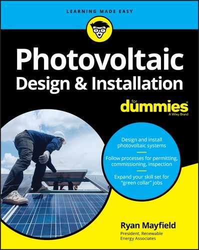
This lack of clear guidelines has caused PV installers to seek outside help with connecting modules. Currently, two methods are used (see Figure 17-1):
- Ground lug: By attaching a ground lug that’s rated for outdoor use (and direct burial) to the back of each module and connecting a conductor to each lug in the array (see Figure 17-1a), you can place the lug at the location provided by the manufacturer (although this location may not be in a convenient place based on your chosen mounting method). However, attaching ground lugs is a time-consuming and detailed process.
-
Grounding clip: By placing a specific grounding clip between the module and the racking system, you can bond the modules to the mounting rails (in other words, you can establish electrical continuity). A grounding clip pierces both the module and the racking system at the same time, bonding the two together (see Figure 17-1b) and allowing you to use the mounting rails as the EGC, eliminating the need to run wire all along the back of the array. You need to connect all the rails together to maintain a continuous grounding path, but you can do this pretty easily before installing any of the modules. After all the modules have been installed and bonded to the rails, you can connect a single EGC to one of the rails and bring it into the junction box (or combiner box) with the grounded and ungrounded current-carrying conductors from the array.
Using grounding clips isn’t as labor intensive as using ground lugs, but it isn’t a foolproof method. You absolutely have to make sure that you place the grounding clips in the appropriate locations (as specified by the manufacturer of the grounding clips you’re using) and that the grounding clips are engaged properly (meaning they’re in full contact with the module and rack). If you install grounding clips incorrectly, then the module won’t be properly bonded to the rail. Also, grounding clips are only rated for a single use. So if you tighten them to the rail and then want to move something, you must replace them.
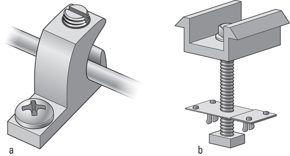
FIGURE 17-1: Equipment-grounding options for PV modules.
Both the ground lug and grounding clip methods allow you to install a continuous ground path for the PV modules. Make sure that if any module is ever removed from the system, the path to ground for all the other modules isn’t interrupted. If you use the lug method, this generally means you have to use a continuous conductor. If you use grounding clips, then as long as all the modules are properly bonded to the rail (which is the path to ground), the ground path won’t be removed until the racking system is removed.
Sizing equipment-grounding conductors
An EGC is sized based on the requirements set forth in the NEC®. For PV systems, the size is primarily based on the OCPD used in the circuit (I explain how to size these devices in Chapter 13). This sizing methodology also assumes that a ground fault protection (GFP) device is installed in the system. In Article 690.45, the NEC® refers you to a table to determine the size of your EGC based on the amperage rating of the OCPD protecting the circuit. All you have to do is find the OCPD rating and move across the table to find the minimum EGC size required.
As I explain in Chapter 13, not every PV system requires OCPDs. When dealing with one that doesn’t, you must size the EGC by assuming that the OCPD amperage rating is equal to the PV-rated short circuit current and using that value in the table in Article 690.45 of the NEC®. You can never use an EGC smaller than 14 AWG, though, regardless of the module’s short circuit current value.
The NEC® has special provisions for PV arrays that are installed in systems where no GFP is present. In these scenarios, you must size the EGC to have an ampacity rating of at least two times the conditions of use ampacity for the current-carrying conductors (I touch on conditions of use in Chapter 13). In this scenario, you need to refer to the conductor ampacity tables (NEC® Tables 310.16 and 310.17) to find the right size for the EGC. This requirement is in place to account for the possibility of current flowing continuously though the EGC in a fault condition.
However, most PV systems need to have GFP installed. Luckily for you, all grid-direct inverters come standard with GFP built in, and a GFP device is easy to integrate into battery-based systems (as I note in Chapter 10).
When sizing your EGC, you need to consider whether it’ll be subject to physical damage. If it will, the EGC must either be physically protected (in conduit) or be a minimum of 6 AWG. The interpretation of “subject to physical damage” may mean something different to you and me. I know of jurisdictions that consider any EGC on the back of an array subject to physical damage, but other jurisdiction-powers-that-be may not see it that way and only require the NEC® minimum. The best practice is to size the EGC equal to the current-carrying conductors (as a minimum). But to be absolutely safe, call the electrical inspector in the jurisdiction where your client is located before installing the system. Sure, this phone call may seem like an extra hassle, but just think of the time it’d take to remove the wire you originally installed and replace it with another if you didn’t call to find out the jurisdiction’s preferred EGC size beforehand.
System grounding
All the EGCs you run will be connected to system grounding. The system ground is composed of a grounding electrode (GE) and a grounding-electrode conductor (GEC).
-
The GE is the conductive object in direct contact with the earth. It’s often a ground rod — a copper rod that has been driven 8 feet into the ground (some jurisdictions require two ground rods driven a minimum of 6 feet apart and also that the two be bonded together; if you’re adding new GEs, make sure you know what the jurisdiction requires).
Another commonly used grounding electrode is called a Ufer ground. This is where the steel reinforcement in the concrete foundation of a building is used as the contact with the earth.
- The GEC is the conductor that connects the grounding electrode (either a ground rod or a Ufer ground) to a point where all the other grounded conductors can be connected. Typically, this point is a 6 AWG or 4 AWG wire that’s connected to the grounding electrode on one end and the ground busbar inside the MDP on the other end. (A ground busbar is where all the EGCs are terminated; it’s in direct contact with the metal MDP enclosure.)
Article 690.47 is the main NEC® reference for PV system-grounding requirements; a number of changes were made to this article in the 2008 version of the NEC®. I walk you through the commonly accepted and generally approved methods for connection and sizing in this section.
Making the system ground connection
For utility-interactive PV systems (either grid-direct or battery-based), the PV system grounding is connected to the existing system grounding installed for the utility system. You can make this happen in a couple different ways. Note: The method you choose depends on the location of your inverter and its relation to the existing grounding-electrode system.
Figure 17-2 helps illustrate the two common ways to make the system-grounding connection in a utility-interactive system:
- A ground rod (or two) connected to the inverter system grounding by a 6 AWG GEC: Keep in mind that you must connect the existing GE (from the utility) to this new grounding-electrode system you just installed. The new and existing GEs must be connected together with a GEC that’s the same size as the existing GEC from the utility. (See Figure 17-2a.)
- A GEC that’s run from the inverter to the existing GE: As long as the GE from the inverter is continuous and sized based on the NEC® requirements (I cover the sizing in the next section), most jurisdictions accept this grounding method (shown in Figure 17-2b). You can even use this GEC to bond the equipment installed on the AC side of the system as it runs through the equipment. You can’t break this GEC, but you can crimp EGCs to the GEC inside the equipment to bond the equipment to the GEC. This method provides the low-resistance bond to the grounding system that the Code wants you to get.
FIGURE 17-2: System-grounding options for utility-interactive PV systems.
For stand-alone, battery-based systems, you must install a brand new GE (because there won’t be one from the utility). You then have to connect two GECs, one originating from the AC MDP and the other from the DC wiring enclosure (where the inverter connects to the battery bank). These GECs will be either 6 AWG or 4 AWG, depending on the GE.
Sizing system grounding
As with the EGC that I describe earlier in this chapter, the GEC must be sized based on the requirements as listed in the NEC®. Article 690.47 references the grounding Code article to determine the correct size. In short, the GEC has to satisfy the requirements for the AC side (Article 250.66) and the DC side (Article 250.166). Article 250.66 includes a table to reference, and Article 250.166 outlines the different possibilities and the requirements for each. For utility-interactive systems, whether grid-direct or battery-based, a GEC that meets the AC portion of this requirement is already installed by the original electrical contractor who installed the electrical system; this GEC has already met the Code requirements. Stand-alone, battery-based systems, on the other hand, require a new GE and GEC be installed as described in the preceding section. In all three system types, the GE is installed as close to the MDP as possible. When sizing a GEC to meet the DC portion of the requirement, the size should be no smaller than an 8 AWG conductor.
Of course, the final size of the GEC depends on the location of the GEC and the existing GE. For example, if the GEC is going to be exposed to physical damage (meaning it’ll be run outside without conduit), it needs to be at least 6 AWG. The size of the conductor provides it with some physical protection. If you can run the GEC from the inverter to the GE without exposing it to damage, an 8 AWG GEC for the DC side may suffice. These sizes often work well for residential and small commercial systems.
Connecting to the Utility
For utility-interactive systems (both grid-direct and battery-based), you need to make an interconnection to the utility grid. This interconnection point can be accomplished in a variety of ways, but regardless of your point of interconnection (or the type of utility-interactive system, for that matter), you must meet a number of NEC® requirements. The next sections highlight the requirements you’re most likely to encounter on a regular basis and explain the different types of interconnections you can make.
Determining the utility’s requirements
Anytime you’re installing a utility-interactive system, the utility will want to know that you’re connecting to its grid with a PV system as opposed to having a PV system connected to its grid without its knowledge (known as guerrilla solar). By now, most utilities in the United States are familiar with the process and have some standard paperwork available, typically a net-metering agreement. Here are the standard contents your average net-metering agreement should contain (the agreement in a particular jurisdiction may include additional points):
- The system owner agrees to some fundamental equipment requirements to ensure the safety of the utility’s workers.
- The utility outlines how it’ll calculate the energy sent to the utility and the amount sent to the home or business (this is generally referred to as the true-up period).
- Special utility-mandated safety requirements are noted. (The number-one piece of safety equipment required is a visible and lockable disconnect, which may be the same disconnect that you install to comply with the NEC®; see the earlier “Locations for disconnecting means” section for more on this).
If you’re installing PV systems in a specific utility’s area, I suggest requesting a copy of the net-metering agreement before you ever talk to customers. That way you know what the utility requires before you even set foot on someone’s roof and can be thinking through all those requirements during the site survey (which I describe in Chapter 5). Having a list of the utility’s requirements ahead of time can help you avoid any surprises (like unplanned disconnects) at the end of the job when they’d be very expensive for you to fix. (That’s right. You’re on the hook for mistakes like this because it’s your responsibility to know the requirements.)
Many utilities want to see a disconnect they can walk up to 24/7 and disconnect the PV system from the utility grid. Figure 17-3 illustrates the common location for a utility-required disconnect (which is before the inverter interconnects to the utility and next to the existing utility meter). The idea is that if a utility worker is working on the lines, the disconnect gives him the ability to disconnect the PV array from the grid and eliminate the possibility of being shocked (or killed) from a PV system. The reality of the situation is that any properly installed inverter will shut down as soon as the utility goes away (see the anti-islanding discussion in Chapter 9). Some of the largest utilities have eliminated or relaxed their requirements, indicating a higher level of comfort with PV technology and the safety equipment already installed. If the utility you’re working with does require the disconnects, you may be able to start a dialogue to eliminate this requirement by doing your research on these other utilities.

FIGURE 17-3: A typical utility-required disconnect location.
Making a load side or line side connection
To meet the NEC® requirements for connecting to the utility, you have to refer to NEC® Article 690.64 (if you’re working with the 2011 version of the NEC®, it’s Article 705.12). The following sections set the requirements PV system installers are held to, depending on the interconnection point: load side or line side.
- In residential applications, you typically achieve an interconnection to the utility by placing a circuit breaker inside the MDP and connecting the inverter output circuit to that breaker. It’s the easiest method of connecting the inverter because adding a breaker to an MDP is a straightforward process. Connecting to the utility this way is known as a load side connection because you’re connecting to the load side of the main OCPD in the MDP.
-
If adding a breaker to the MDP isn’t an option (because the MDP is full or the PV array output is too large), you can make a line side connection, which is when you connect the inverter’s output circuit to the utility before it reaches the main OCPD in the MDP. This approach is common in commercial applications.
If you want (or need) to connect to the line side of the main OCPD, you should discuss the options with the local electrical inspector. This method requires you to make connections that the inspector may not be familiar with, and walking through the options beforehand instead of after you’ve installed the system can save you a lot of trouble.Note: If you need to interconnect with the utility at this point, you should be aware of the following main Code requirements:
- You need to have a disconnect and OCPD immediately adjacent to the point of interconnection. This disconnect should be grouped (located) with the other disconnects for the facility.
- The disconnect should be rated for at least 60 A, and you must use a fused disconnect to meet the OCPD requirement. However, the fuses can be less than the 60 A specified, based on the inverter output current.
- You can’t have more than six disconnects to shut off all the power sources. This requirement means that if you’re in a commercial facility that has six disconnects already installed, you can’t add a seventh one for the PV system; instead, you must find a way to disconnect all the power sources with fewer than six switches.
For the more common systems that are installed on the load side of the main OCPD, the NEC® has seven different requirements you need to meet. Addressing and meeting all seven requirements may seem daunting at first, but in reality, all seven requirements are achievable for the majority of your installations. I note the requirements in the following sections.
Placing each inverter on its own circuit breaker or disconnect
Each source interconnection must be made on a dedicated circuit breaker (or fusible disconnect). This requirement is in place to ensure that all the inverters are connected to their own OCPD. If they are, then they’re protected adequately and can be properly isolated.
Using a circuit breaker with the correct rating
The busbars inside the MDP (or subpanel) you connect the circuit breakers to have an ampacity rating just like all the conductors in your system. This provision in the Code allows the sum of the circuit breakers supplying power to the busbar (in other words, the main OCPD from the utility and the PV breaker) to exceed the busbar rating by 120 percent.
This means that, for example, you can have an MDP in your home that has a busbar rating of 200 A (you can find this information on the label inside the main cover) and a main OCPD (main breaker) rating of 200 A (both of these are very common ratings for the equipment installed in many homes) and still install a PV system on that panel because of the 120-percent rule.
To determine the maximum PV breaker you can put on this MDP, find the busbar rating, multiply it by 120 percent, and subtract out the existing main OCPD size. For the 200 A busbar and 200 A main OCPD example:
- 200 A × 120% = 200 A × 1.2 = 240 A
- 240 A – 200 A = 40 A (the maximum inverter breaker size)
You can only operate that PV breaker at 80 percent of its rating continuously, so the maximum inverter output current is limited to 32 A (40 A × 80%). You determine the maximum inverter output current value in Chapter 13.
Working with ground fault protection integrated into an overcurrent protection device
If the main OCPD has a ground fault protection (GFP) device built into it (which is typical for larger commercial systems but unheard of for residential systems and rare for small commercial systems), the main OCPD must be listed for current flowing backward through it. This provision is why line side connections are so common for larger commercial systems. Finding a main OCPD with integrated GFP listed for current flowing the “wrong” way is a difficult task to say the least.
Making your mark on panels with multiple power sources
You have to properly mark any electrical panel (whether MDP or subpanel) that has both utility and PV sources to alert any emergency personnel that this electrical system has multiple power sources. Also, if you connect the inverter to a subpanel, you must place a label on the MDP as well, indicating the presence of the PV array and where to find the disconnecting means.
Ensuring that circuit breakers can be backfed
The circuit breakers you use must be suitable for backfeeding (having current go to the utility rather than a load). Some circuit breakers only work with current flowing from the utility to the load. If you put current the other way (from an inverter to the utility), the circuit breakers may not be able to properly protect the conductors and equipment.
This backfeeding requirement really only affects you if the circuit breakers you want to use are labeled with line and load directly on the breaker. If you don’t see these designations, you’re okay.
Understanding that fastening kits aren’t required
Some inspectors have required PV installers to install fastening or “hold-down” kits for the PV circuit breakers. The thought process behind this mandate was that if the breaker comes off the MDP busbar, it’ll still be “hot” and have the potential to cause shock and fire hazards. Of course, this scenario can’t actually happen due to the anti-islanding requirements of today’s inverters. A provision can now be found in the Code that specifically states that these fastening kits aren’t required.
Locating the protection
The final provision/requirement dictates where the PV circuit breaker is installed. If you exceed the busbar rating with the utility and PV breakers (which you will 95 percent of the time or more), the PV breaker must be installed on the opposite end of the busbar from the utility breaker. Why? Because if the currents are flowing in opposite directions, no place on that busbar will ever be exposed to more current than its rating allows.
You also have to label the PV breaker with a warning that no one can ever relocate the breaker in the panel. This label’s purpose is to ensure someone doesn’t come in behind you and move the breaker without realizing the possibilities for overloading the busbar.