Chapter 9
Canal Architecture
Abstract
Canal architecture is nothing but a canal network laid over the irrigation command such that irrigation water supply can be made equitably throughout the command area. This chapter describes a detailed procedure, including the extent of investigation for laying down the canal system and alignment over the irrigation command. For enhancing the understanding of the canal system, this chapter provides insights into the classification of canals, based on their function, alignment, discharge capacity, etc., using figures. The practical application of the canal alignment process using the topographic surveyed data or toposheet is also included in the chapter through worked example.
Keywords
Alignment; Canal alignment; Canal classification; Command area survey; Discharge capacity; Function; Nature of supply
The aim of irrigation project is to bring water by gravity or lift flow from its source (dam, diversion head-works, river, etc.) through a system of canals (main canal, branch canal, distribution system) to the fields and subsequently through water courses to agricultural fields. Therefore the canal and its alignment play a vital role in an irrigation project.
Planning of an irrigation canal network involves the following main components:
1. Survey of the area under command
2. Canal alignment
3. Marking and finalization of the area proposed to be irrigated by each channel
4. Design of canal
The data required for planning and layout of a canal system are as follows (IS 5968, 1987):
1. Topographical map of the area,
2. Subsurface data,
3. Texture and salt composition of the soil,
4. Soil characteristics including mechanical properties and shear parameters,
5. Permeability of soil in relation to seepage loss,
6. Rainfall data,
7. Water availability,
8. Subsoil water level in the area and quality of the underground water,
9. Possibility of water logging and salinization,
10. Availability of suitable construction materials,
11. Existing irrigation and drainage facilities,
12. Existing crop patterns,
13. Existing communication and transportation facilities, and socioeconomic study and agroeconomic survey of the project area.
Adequate investigations shall be carried out to collect the data given by digging trial pits or bore holes, where necessary, to ascertain the nature of soil encountered along different alternative alignments. For general guidance regarding the suitability of soils for use in canal embankments, IS 1498 (1970) and IS 4701 (1982) can be referred to.
9.1. Canal Classification
A canal is classified according to its source, function, discharge and importance, and canal alignment as discussed in the following sections.
9.1.1. Classification According to Function of the Canal
2. Carrier canal: A “carrier canal,” besides doing irrigation, carries water for another canal (upper Chenab canal in West Punjab, Pakistan, is an example).
3. Feeder canal: A “feeder canal” is constructed primarily to convey water from one source of supply or system to another within the same system, when the off-taking channels are already in existence and have to be grouped together (Fig. 9.1).
4. Navigation canal: A “navigation canal” is primarily used for transportation by water.
5. Power canal: A “power canal” or a hydel channel is a canal or reach of canal that is primarily used to carry water to a powerhouse (Fig. 9.1).
9.1.2. Classification According to Alignment
According to the alignment of channel, canals may be classified as follows:
1. Watershed ridge canal: A ridge canal or a water-shade canal is aligned along a water-shade and runs for most of its length on a water-shade (Figs. 9.1 and 9.6). It can have command areas on both banks and so a large area can be brought under cultivation. No drainage can intersect a water-shade and hence the necessity of constructing cross-drainage works.
2. Contour canal: A channel aligned nearly parallel to the contours of the country is called a contour canal. When a canal takes off from a river or a dam or a diversion head-works in a hilly area, it is not possible to align the canal on the water-shade, as the water-shade on the top of hill may be very high and the areas that need irrigation are concentrated in the valley at lower levels (Figs. 9.2 and 9.6). The canal is then aligned roughly parallel to the contours of the country. The contour chosen for the alignment should be placed so as to include all culturable area of the valley on one side of the canal.
The contour canal can irrigate only on one side, and if the ground levels on the other side are quite high there is no necessity of bank on this side. This type of canal is called “single bank canal.” However, when both banks are provided, it is known as “double bank canal.” The rate at which the canal alignment leaves one contour and takes up another depends on its surface slope.
3. Side slope canal: It is a channel aligned roughly at right angles to the contours of the country and is neither on the water-shade nor in the valley and is roughly parallel to the natural drainage of the country, and it does not intercept any cross-drainage.
In general, a major canal alignment has a combination of a ridge canal and a contour canal, and the minor channels, water courses, and field channels can be partly side slope canals.
9.1.3. Classification According to Nature of Source and Supply
1. Permanent canal: A canal is said to a permanent canal when it is fed by a permanent source of water supply, i.e., it has a permanent head-works for diversion of river water to the canal. It is also sometimes known as perennial canal when the source from which the canal takes off is a snow-fed perennial river and is designed to irrigate all the year round.
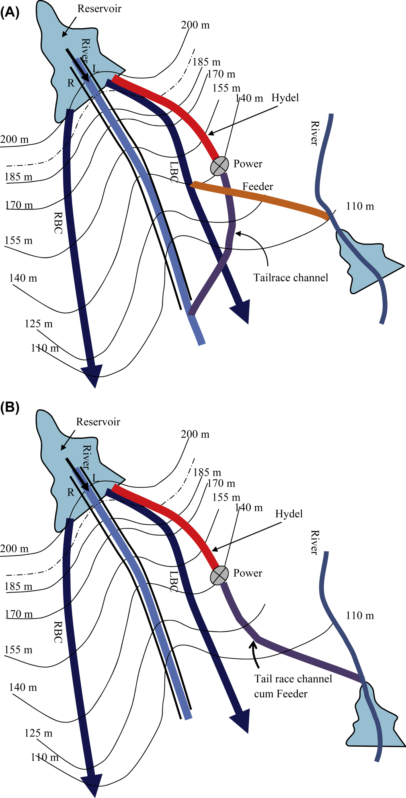
Figure 9.1 (A) Classification of canals as per their function. (B) Classification of canals as per their function.

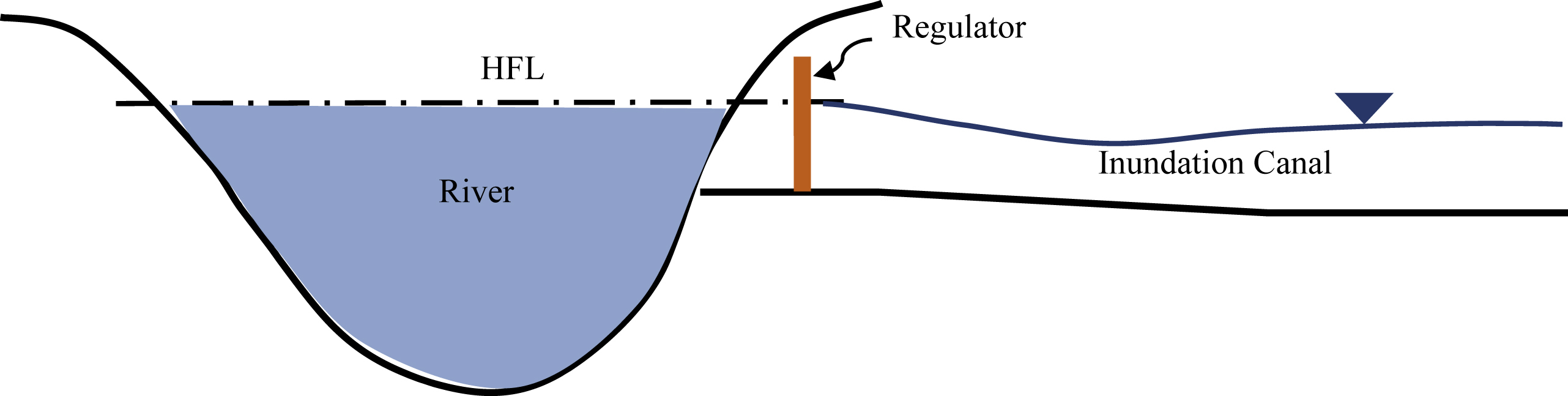
2. Inundation canal: Inundation canals (Fig. 9.3) usually draw their supplies from river, whenever there is high stage or flood in the river. They are not provided with any head-works across the river for diversion of water to the canal. Inundation canal are useful to use the flood water for irrigation. When there is early flood, kharif crop can be irrigated by flood water at the beginning period, whereas when late flood occurs after the rainy season, rabi crops can also be irrigated. Inundation canals are also useful in flood protection.
9.1.4. Classification According to Discharge and Relative Importance
A network of irrigation canal systems consists of the following channels (Fig. 9.4):
1. Main canal: The main canal takes its supply directly from the diversion head-works on a river. It carries heavy supplies and is not for direct irrigation except in exceptional circumstances for isolated patches inaccessible to other channels. It acts as a carrier to feed supplies to the branch and distributary or minor canals. Branch canals are mostly in major irrigation projects [culturable command area (CCA) more than 10,000 ha].
2. Branch canal: The canal off-taking from the main canal with substantial discharge is termed as branch canal. In general, branch canals also do not carry out any direct irrigation. These are feeder channels for distributaries and minors. Medium (CCA more than 2000 ha and up to 10,000 ha) or minor irrigation (CCA up to 2000 ha) projects normally do not have any branch canal. The capacity at the head of branch canal is generally not less than 10 cumecs.
3. Distributary: It takes off from a branch canal or where there is no branch canal directly from main canal. Distributaries and minors are real irrigation channels in the sense that they supply water for irrigation to the fields through outlets provided along them. The discharge of a distributary is between 1.5 and 10 cumecs.

4. Minors: Minors take off directly from branch or distributary or main canal. They supply water to the water courses through outlets provided along them. The discharge of a minor is between 3–4 cusecs and 1.5 cumecs.
5. Water course: It is a small channel that receives water through outlets fixed in the banks of distributary or minors for supplying water to the fields. Water courses are owned and maintained by cultivators themselves. They normally do not carry water discharge at the head more than 3–4 cusecs.
9.2. Command Area Survey
For planning of a canal network, two types of survey maps are required: one for initial planning of the system as a whole and the other for detailed planning of the canal network.
9.2.1. Survey Maps for Initial Planning
The survey maps for initial planning of the system may be on 1:250,000 or 1:50,000 scale with contour intervals of 2.5–5.0 m, including other ground features, such as road, rails, villages, and forest marked. These maps broadly depict the topographical features and greatly help in canal network planning system as a whole.
9.2.2. Survey Maps for Detailed Planning
For detailed planning of a canal network, survey maps should be on a 1:15,000 or 1:10,000 scale depicting complete topographic details along with the location of benchmarks, trees, ponds, village roads (kutcha tracks), etc. For detailed planning of alignments, contour intervals of at least of 0.5–1.0 m should be there.
Survey of India (SOI) develops aerial survey maps with the help of ground controls. These maps are general-purpose topographical maps depicting broad features and are on a 1:250,000 scale and are called one-degree maps. These can be used as guide maps for the area. The maps on a 1:50,000 scale are also developed by SOI as per requirement of the concerned department. In India, SOI is the prime organization entrusted with the job of topographical survey. SOI conducts surveys as per the State policy of the country as a whole. This is generally aimed at surveys and their development with ground control and conventional surveys in the field. For major projects, these SOI maps are used for canal planning. However, for minor irrigation schemes, locally surveyed maps serve the purpose, and if required additional survey can be carried out as per requirement.
A detailed contour map of the area is the first and foremost requirement for the general feasibility planning of the project as a whole and second for estimation of individual components of the canal part of the project. For the most suitable alignment of canal, survey maps are to be prepared to a scale of 1 in 15,000 or 1:10,000 showing the contours, spot levels, and important land features for the whole area to be developed.
9.3. Canal Alignment
A canal has to be aligned in such a way that it covers the entire area proposed to be irrigated, with the shortest possible length, and at the same time its cost, including the cost of cross-drainage works, is a minimum. Irrigation channels are necessarily located on the water-shades of the country traversed so that water may reach the desired fields with ease and minimum expense. A shorter length of canal ensures less loss of head due to friction and smaller loss of discharge due to seepage and evaporation so that additional area can be brought under cultivation.
Once the detailed survey maps with contours are available for the area to be served, ridge lines and valley lines should be marked on the shajra maps (revenue maps marked with individual farmer's land and other land/habitation, etc.) to determine individual chak and outlet position. Alignment of main canals, distributaries, and minors should be marked on the cadastral map (shajra), including possible alternatives.
9.3.1. Important Points for Canal Alignment
The following points have to be kept in mind while aligning the canals (IS 5968-1987):
1. As far as possible the line of canal should follow the watershed or ridge or the highest line of the irrigable lands, but it is not always essential to select the highest ground/elevation as it may place the whole channel requiring very heavy cutting and thus may unnecessarily add to the cost of the canal
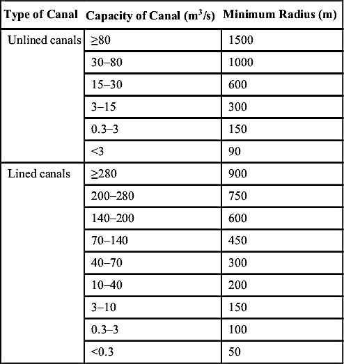
Table 9.1
Minimum Radii for Canal Curves
| Type of Canal | Capacity of Canal (m3/s) | Minimum Radius (m) |
| Unlined canals | ≥80 | 1500 |
| 30–80 | 1000 | |
| 15–30 | 600 | |
| 3–15 | 300 | |
| 0.3–3 | 150 | |
| <3 | 90 | |
| Lined canals | ≥280 | 900 |
| 200–280 | 750 | |
| 140–200 | 600 | |
| 70–140 | 450 | |
| 40–70 | 300 | |
| 10–40 | 200 | |
| 3–10 | 150 | |
| 0.3–3 | 100 | |
| <0.3 | 50 |
3. The ideal design and alignment are those in which the earth obtained from cutting in the bed is equal to the earth required for formation of banks. This is called economical cutting/excavation, and the channel is said to be in balancing depth.
4. The most economical condition is when the canal water runs partly within and partly above the ground level so that cutting may balance embankment and there is also sufficient command of level for irrigation.
5. The alignment of the canal should be such as to ensure (1) the most economical way of distributing water to the land, (2) as high a command as possible, and (3) minimum number of cross-drainage works. The contour alignment should be changed this way or that way to reduce the number of cross-drainage works to a minimum
6. The number of kinks and acute curves should be minimum, as these disturb the regime of the canal. The concave side is always under erosion, and the convex side has a tendency to silt. The radii of curve should usually be 10–15 times the bed width.
A few more points shall also be considered while layout planning of a canal, which are as follows:
• As far as possible, curves should be avoided in the alignment of canals because curves lead to the disturbance of flow and a tendency to silt on the inner bend and scour the toe of the outer (concave) bend. However, if curves have to be provided, they should be as gentle as possible. Furthermore, the permissible minimum radius of curvature for a channel curve is shorter for lined canals than for unlined ones and is shorter for small cross-sections than for large cross-sections of canals. According to the Bureau of Indian Standard code IS 5968-1987 “Guide for planning and layout of canal system for irrigation,” the radii of curves should usually be 3–7 times the water surface width subject to the minimum values as given in Table 9.1.
• The alignment should be such that the cutting and filling of earth or rock should be balanced, as far as possible.
• The alignment should be such that the canal crosses the natural stream at its narrowest point in the vicinity.
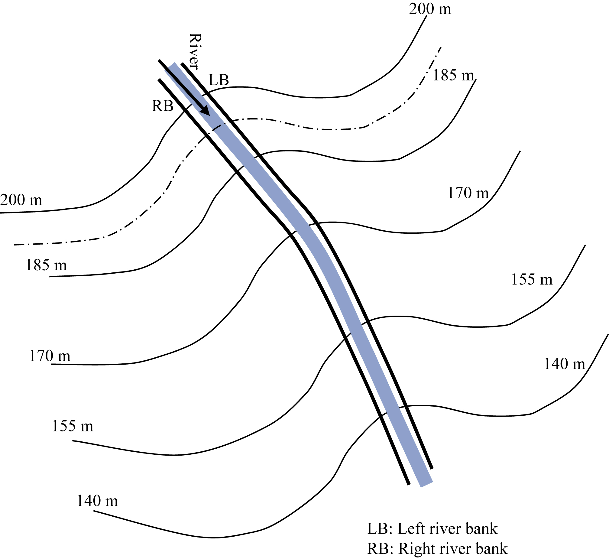
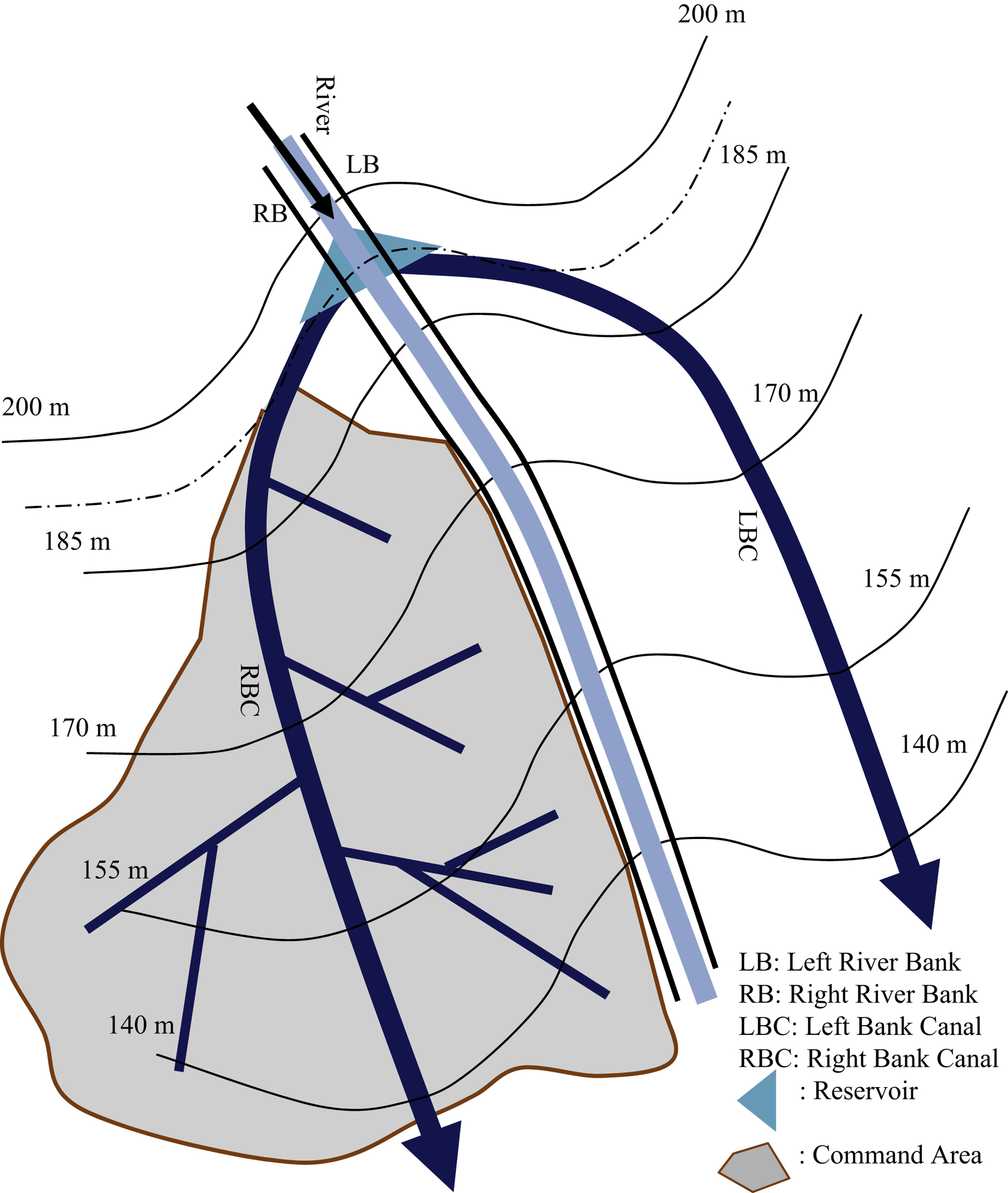
Example 9.1: For a given topographic (contour) plan of the watershed (Fig. 9.5), draw a feasible plan of the main canal.
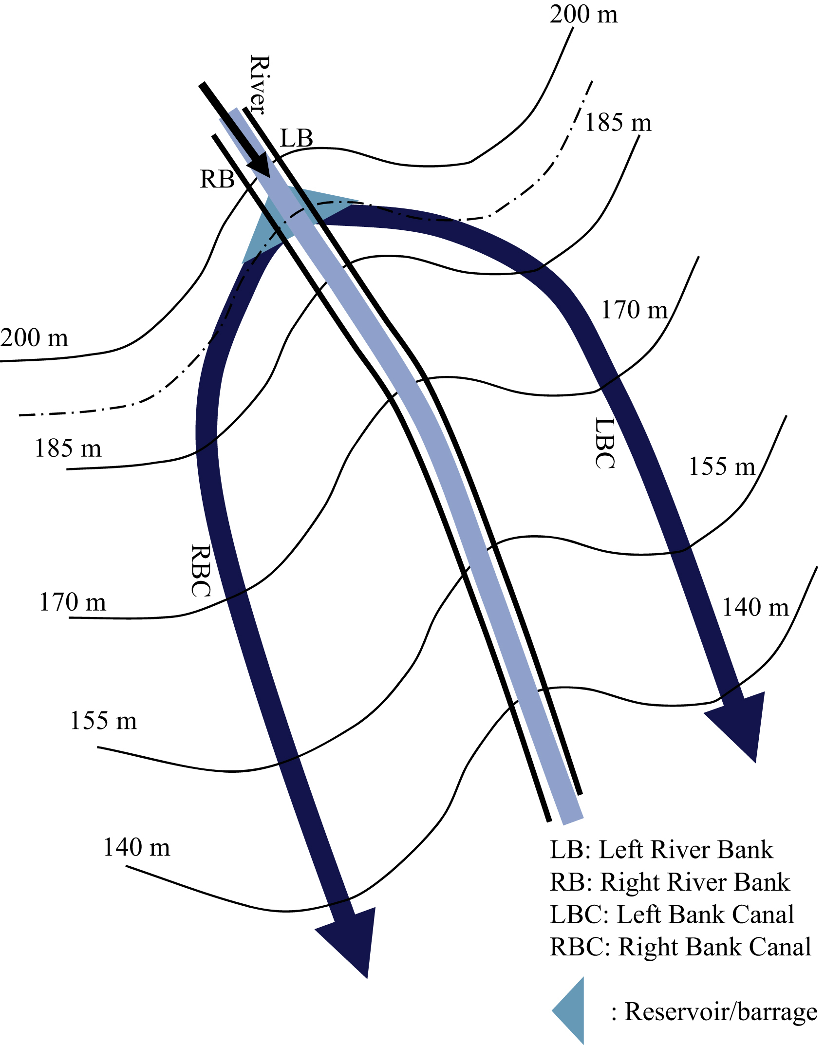
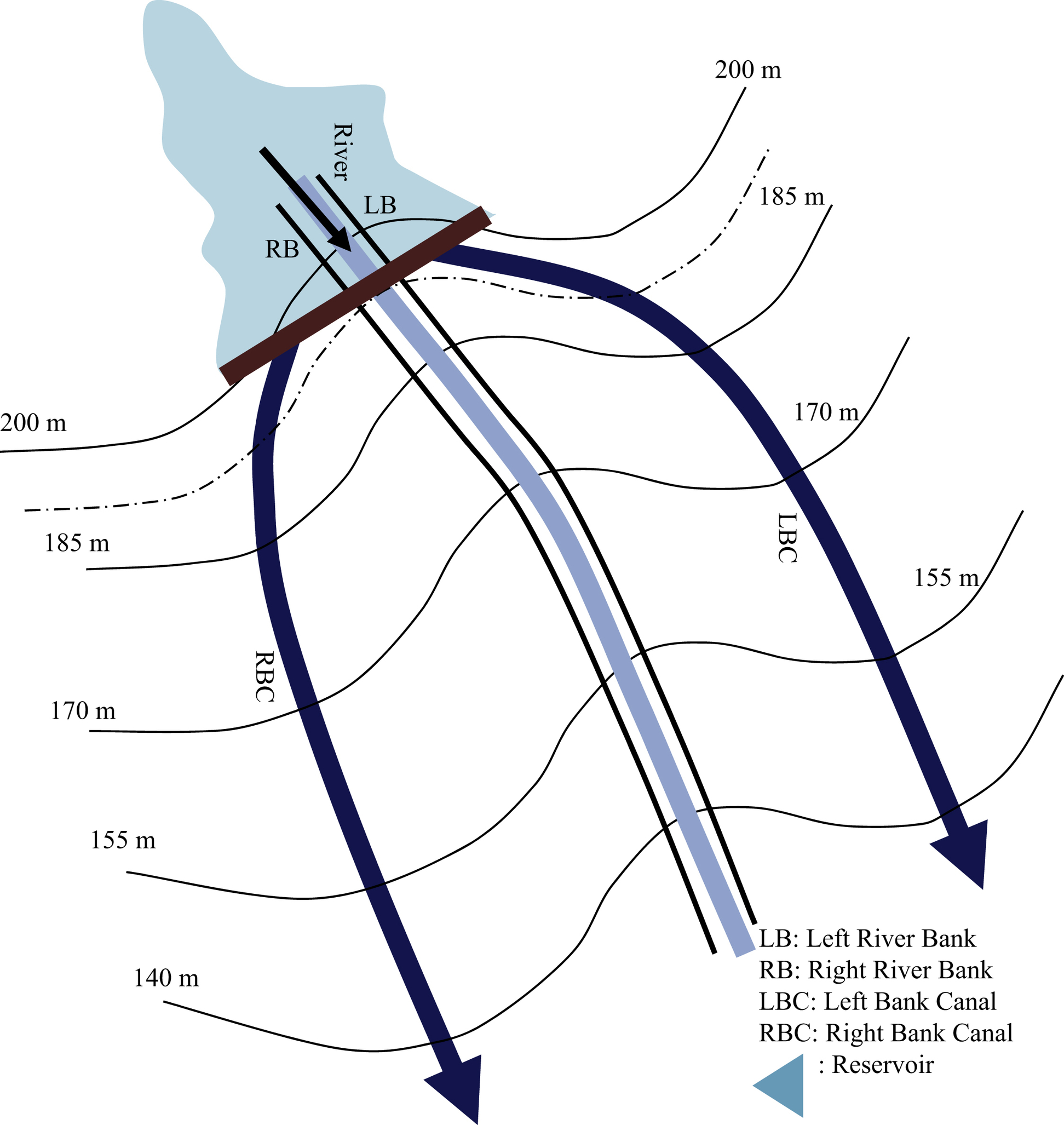
Solution: The objective of laying out the main canal over the command area should be such that: (1) flow in the canal should be due to gravity and (2) area irrigated should be as much as possible by the canal system. Canal layout should be viewed from the off-take point from the river. If off-take point is considered as the dashed line passing through the river, then two canals can off-take from the river's diversion structure or dam known as LBC and RBC. Both canals should follow the watershed divide so that maximum area can be covered on both sides of the canal (Fig. 9.6). A distributary or minor canal should off-take from the main canal and follow the natural ground slope toward the valley. If the dam is long, then canal can off-take from the dam body and run along the watershed divided or ridge (Fig. 9.7). The command area plan for the given example is shown in Fig. 9.8.
9.4. Marking and Finalization of Area Proposed to Be Irrigated by Each Channel
After the alignment of the channels (main canal, branch canal, distributaries and minors, etc.) has been settled, the area proposed to be irrigated by each channel is marked on the cadastral or shajra plan. It is essential that the boundaries of command areas of various channels follow the natural drainage line. The area to be irrigated by each channel, i.e., gross command area, and the CCA is worked out on the land use map showing the area already under cultivation, habitation, drainage, and soil type. Once the area to be irrigated is decided, the head discharge is worked out with the help of draw-off statement in which the discharge is worked out for different areas and channels from tail to head.
9.5. Design of Canal
Once the alignment of the canal system is marked, the area to be irrigated by outlets and each channel, i.e., minor, distributary, branch, and the main canal, is calculated.
The longitudinal sections of the finalized alignments of main canal, branch, distributaries, minors, etc., are marked on the field, and the details are plotted for the design of the canal.
9.6. Concluding Remarks
This chapter describes the canal classification based on canal function, alignment, nature, and discharge capacity followed by procedural description of the planning of canal layout over the command area for equitable distribution of water and efficient utilization of water available. For more detailed understanding, readers are referred to various publications of United States Bureau of Reclamation and Indian Standards (IS)/International Organization for Standardization (ISO) codes.
..................Content has been hidden....................
You can't read the all page of ebook, please click here login for view all page.