Evaluation of Hazard and Risk Analysis
Abstract
Hazards and risks are very plant specific. So, to address the many varieties of risk there are a number of ways to address them. Detailed selection processes are discussed to select the best one suitable for the plant. Hazard analysis is the primary step toward plant hazard analysis (PHA). A rigorous treatment is presented to focus on various factors with special reference to major incidents and for major hazard facilities (MHFs) and HAZID. In addition to outline discussions on various PHA methods, detailed discussions are presented on task analysis to take into account human action errors. Starting from qualitative risk analysis, various independent protection layers are chosen to arrive at semiquantitative risk analysis. Control measures play a very big role in risk analysis. Detailed discussions are presented to address these control measures so that safety of the facilities can be ensured. For complex systems, quantitative risk analysis (QRA) is quite common, so QRA with statistical approaches is covered. Safety management systems are covered to ensure total safety for MHFs. Detailed dialog on risk analysis and management is also a part of the discussions so that the reader can develop one for any specific plant based on the outline discussions covered.
Keywords
1.0. Plant Hazard Analysis Preliminaries
1.1. Fundamentals of Plant Hazard Analysis
1.1.1. What is Hazard Analysis
1.1.2. Aim of PHA
1.1.3. Basic Scope of PHA
1.1.4. Major PHA Steps

1.1.5. Management of Change (MOC)
1.1.6. Typical Output Expected of PHA
1.2. Various Plant Hazard Analysis Methods

1.2.1. Qualitative
1.2.2. Guided Word

1.2.3. Quantitative
2.0. Evaluation of Plant Hazard Selection Techniques
2.1. Preselection Consideration
2.1.1. Basic Plant Facility and Hazard Considerations
2.1.2. Some Important Terms and Quick Methods
Table II/2.1.2-1
Technical Terms Used in PHA (Especially for Chemical Process Plants)

| Terms | Elaboration |
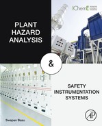
| Mond Index | The Mond Index was developed by ICI's Mond Division as an extension of the Dow F&EI to address the toxicity hazards associated with materials in process units. This is to be used in conjunction with FEI. It is seen that when toxicity is 0–6, it is light with FEI 0–60. Toxicity >10 could be intermediate or heavy depending on associated FEI in the range of 127–158. For FEI >159 and toxicity index >10 it is severe. It relates both FEI and the toxicity Index [2]. Mond indices are classified as “Mild,” “Light,” “Moderate,” “Moderately Heavy,” “Heavy,” and “Extreme” for the ranges 0–20, 20–40, 40–60, 60–75, 75–90, and >90, respectively [4]. |
| Chemical exposure index (CEI) | The CEI is again an index used by Dow Chemical to assess products of various factors (acute toxicity, volatile portion of the material that could be released, molecular weight, distance coverage, and operating parameters like temperature, etc.) using a numeral scale. |
| Substance hazard index (SHI) | The SHI is an index to identify the toxic chemical substances that could be involved in a catastrophic release. The index is a simple function of vapor pressure and toxicity: The higher the vapor pressure, the more rapid will be the entrance in the atmosphere in the event of a release. The greater the toxicity, the lower the concentration required to present a hazard—so, SHI will be higher. |
| Hazardous material and material hazard index (MHI) | Any chemical substance that when released or misused will cause harm to the environment and/or public health. These are used in various industries. Hazardous materials may be in the form of explosives, flammable and combustible substances, poisons, and radioactive materials [5]. MHI is an index used by the State of California. It is the material vapor pressure at 25°C divided by the level of concern, which can be defined on the basis of toxicity, fire explosion, etc. [3,6]. |
| Hazard factor (HF) | There are two kinds of hazard caused by the toxicity, fire, or explosion effect on materials, (1) General purpose, where the intensity of an accident increases on account of its presence. (2) Special purpose, where the probability of an accident increases (Clause 2.1.1). |
2.2. Plant Hazard Analysis Methods Selection Criteria

2.2.1. Aim of PHA Selection
2.2.2. Team Formation and Team Leader
2.2.3. Factors Influencing PHA Method Selections [1]


2.2.4. PHA at Various Stages of the Project
2.2.5. Decision for PHA Method Selection

2.3. Comparison of Various PHA Methods
Table II/2.3-1
Codes for Various PHA Methods (Refer Table II/2.3-2 for Uses of These Codes)
| Code Name Used | PHA Method |
| CL | Checklist (qualitative) |
| WI | “What if” (qualitative) |
| SWI | Structured “what if” (what checklist) (qualitative) |
| PHA | Preliminary hazard analysis (qualitative) |
| FMEA | Failure mode and effect analysis (guided word) |
| HAZOP | Hazard operability (guided word) |
| ETA | Event tree analysis (quantitative) |
| FTA | Fault tree analysis (quantitative) |
| HRA | Human reliability analysis (quantitative) |
| LOPA | Layer of protection (semiquantitative/quantitative) |
| QRA | Quantitative risk analysis (quantitative—different approach) |
Table II/2.3-2
Comparison of Various PHA Methods: To Be Read in Conjunction With Details in Table II/2.3-1. In This Connection Annexure of ISO 31010:2009 May Be Referred to Also
| Main Criteria | Subcriteria | CL | WI | SWI | PHA | FMEA | HAZOP | ETA | FTA | HRA | LOPA | |
| Type (FTA is deductive) | Qualitative | X | X | X | X | |||||||
| Guided word | X | X | ||||||||||
| Quantitative | X | X | X | X | ||||||||
| Team for all | But individual possible∗ | ∗X | ∗X | |||||||||
| Operational mode | Continuous | X | X | X | X | X | X | X | X | X | ||
| Batch/startup/ shutdown | X | X | X | X | X | X | X | X | X | |||
| Hazard level | High | X | X | X | X | X | X | X | ||||
| Low | X | X | X | |||||||||
| Simple/small plant (time in hours/days) | X | X | X | X | ||||||||
| Complex/large plant (days/weeks) | X | X | X | X | X | X | X | |||||
| Experience with system (H for high; L for low) | H/L | H/L | H/L | L | H/L | H/L | H | H | H/L | H | ||
| Information database | F: FEED, D: Detail design | F | F/D/O | F/D/O | F | D/O | D/O | D/O | D/O | D/O | D/O | |
| O: Op unit/startup | ||||||||||||
| Project stages: A: All; F: FEED; E: Detail Engineering.; C: Construction/startup; O: Operation; M: Modification; D: Decommissioning | A | A | A | E/C/M | E/C/M | D/O/M | ||||||
| Team leader expertise M: Minimum; MO: Moderate; E: Extensive | M | M | M | MO | MO | E | E | |||||
| Analysis quality G: Gross; S: Specific; V: Very specific | G | G | G | G | S | S | V | V | ||||
| Failure | S: Single; M: Multiple | S | S | S | S | S | S | M | M | M | ||
| Coverage width | W: Wide coverage; P: Physiochemical | W | W | W | S | S | W | W | ||||

3.0. Hazard Identification (HAZID) and Risk Estimate

3.1. Basics of HAZID
3.1.1. HAZID Concepts and Features

3.1.2. Some Important Definitions and Discussions
3.1.3. Aim of HAZID
3.2. Planning and Preparatory Stage
3.2.1. General Considerations

3.2.2. Scope
3.2.3. HAZID Team Formation
3.2.4. Hazard Identification Technique Selection
Table II/3.2.4-1
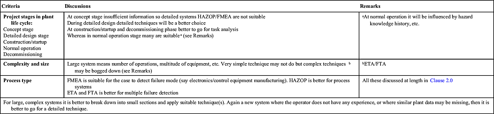
Discussions on Selection Techniques
| Criteria | Discussions | Remarks |
Project stages in plant life cycle: Concept stage Detailed design stage Construction/startup Normal operation Decommissioning | At concept stage insufficient information so detailed systems HAZOP/FMEA are not suitable During detailed design detailed techniques will be a better choice At construction/startup and decommissioning phase better to go for task analysis Whereas in normal operation stage many are suitablea (see Remarks) | aAt normal operation it will be influenced by hazard knowledge history, etc. |
| Complexity and size | Large system means number of operations, multitude of equipment, etc. Very simple technique may not do but complex techniquesb may be bogged down (see Remarks) | bETA/FTA |
| Process type | FMEA is suitable for the case to detect failure mode (say electronics/control equipment manufacturing). HAZOP is better for process systems ETA and FTA is better for multiple failure detection | All these discussed at length in Clause 2.0 |
| For large, complex systems it is better to break down into small sections and apply suitable technique(s). Again a new system where the operator does not have any experience, or where similar plant data may be missing, then it is better to go for a detailed technique. | ||
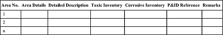
3.2.5. Documentation

Table II/3.2.5-1
| Area No. | Area Details | Detailed Description | Toxic Inventory | Corrosive Inventory | P&ID Reference | Remarks |
| 1 | ||||||
| 2 | ||||||
| n |
3.2.6. Scheduling
Table II/3.2.5-2
| Hazard Worksheet | Accident Category: Category I Description XXXXXXXXXXXX | |||||||||
| ID | Hazard Description | Phase | Cause | Effect | Detection | Subcategory | Regulation | SI | FI | Comments |
| 1.2 | Main ID may be actual/escalation issue under main ID | |||||||||
| 1.2.1 | ||||||||||
| 1.2.3 | ||||||||||
| a.b.c | ||||||||||
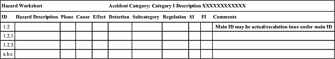
Table II/3.2.5-3
| ID | Hazard/Major Incidenta | Cause | Possible Consequence | Existing Safeguard | Risk Reduction Procedure | Remarks |
| Main Section | ||||||
| Subsection | ||||||
| 1.2 | ||||||
| a.b.c | ||||||


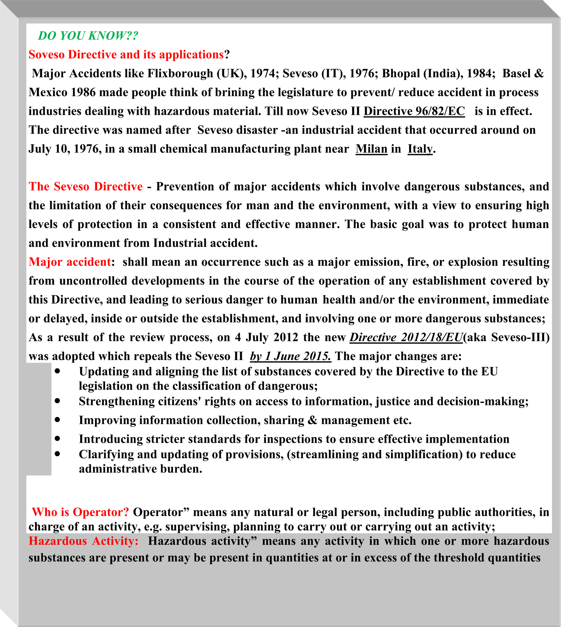
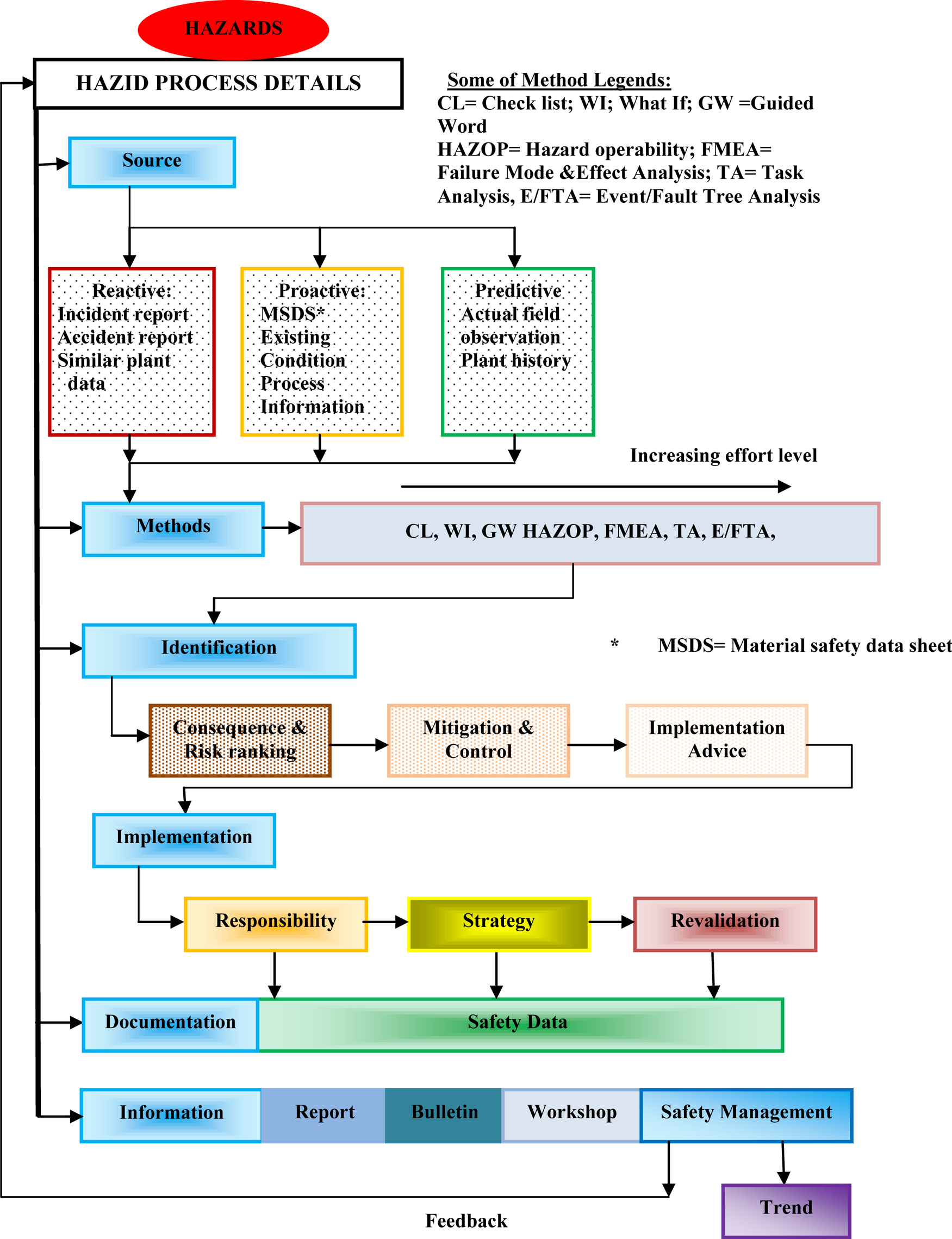
3.3. HAZID Process Description
3.3.1. Information Collection and Handling

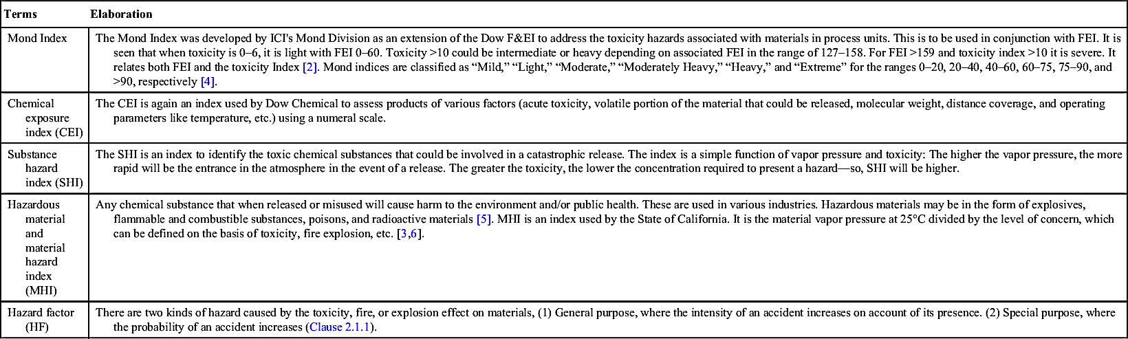
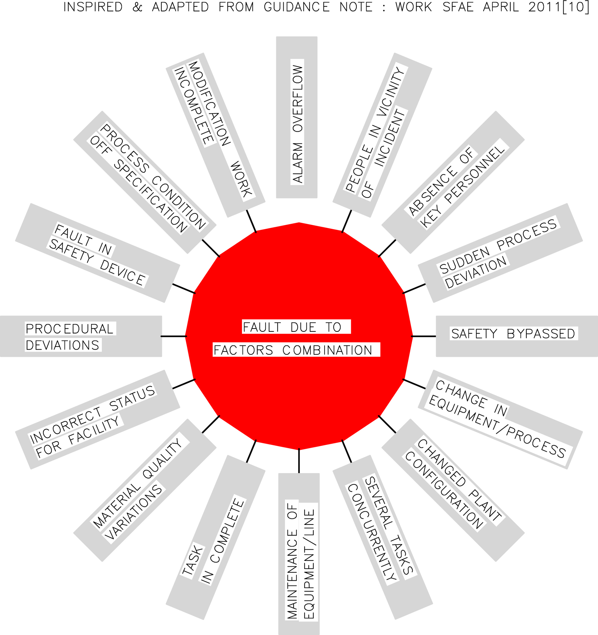
3.3.2. General Considerations and Major Accidents/Incidents

3.3.3. In-depth Analysis
3.3.4. Creative and Lateral Thinking
3.4. HAZID Output
3.5. Review
3.6. Quality Check
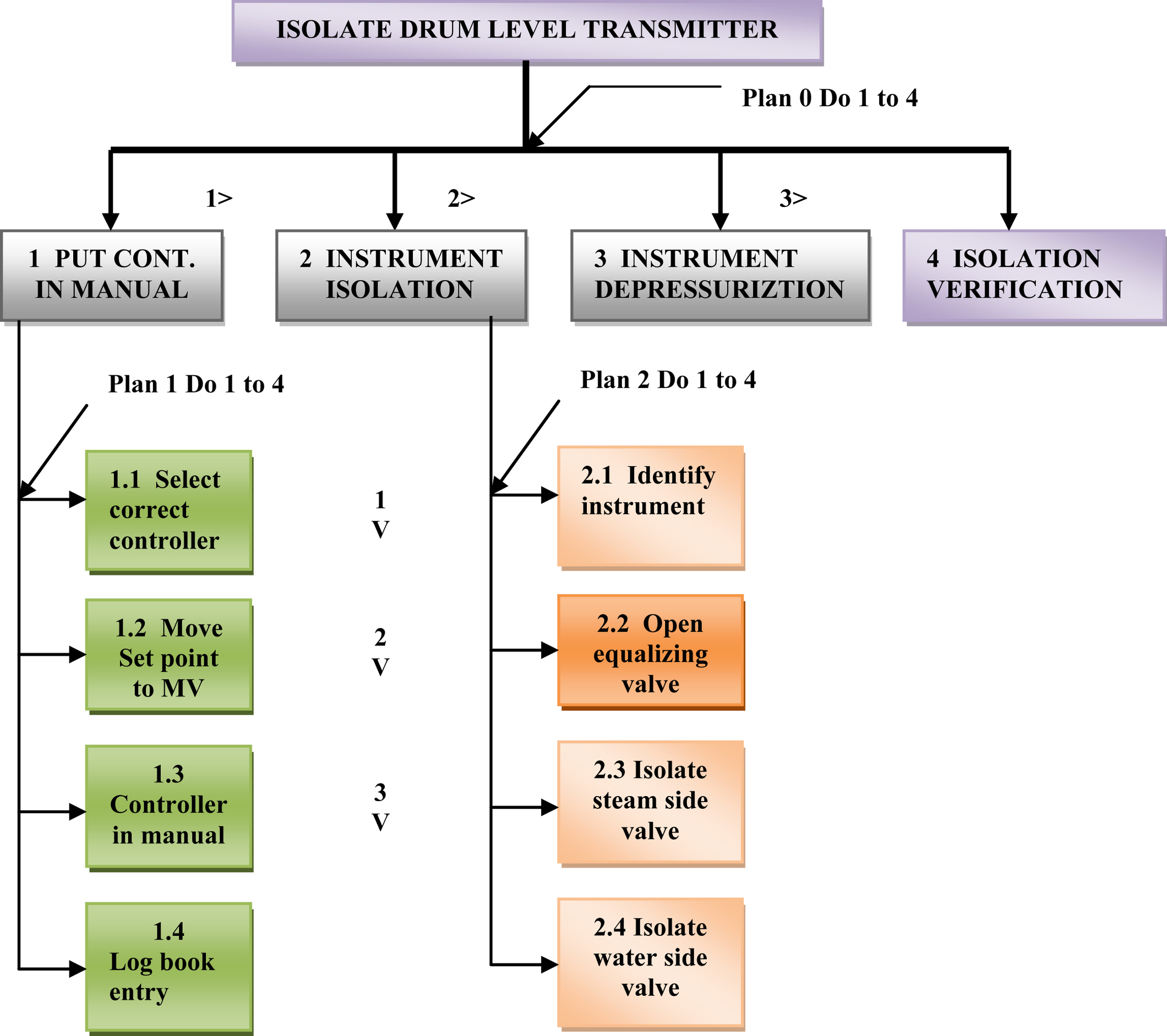
3.7. Task Analysis

3.7.1. Hierarchical (Action-Oriented) Task Analysis
3.7.2. Operator Action Event Tree

3.7.3. Flow Diagram

3.7.4. Critical Action and Decision Evaluation Technique
3.7.5. The Influence Modeling and Assessment System [14]
3.8. HAZID Discussions
3.8.1. Human Factor
3.8.2. Worst Case Scenario
3.8.3. Common Mistakes, Pitfalls, and Suggestions
3.9. Risk Estimate (Brief)

4.0. Risk Assessment and Management
4.1. Risk Analysis Basics
4.1.1. Various Terms and Definitions

4.1.2. Definitions of a Few Related Terms
4.1.3. SFARP/SFAIRP
4.1.4. Objective and Philosophy of Risk Assignment
4.1.5. Features and Framework of Risk Analysis: The Basic Features of Risk Analysis Shall Cover

4.1.6. Standards
4.2. Risk Analysis Prestart Issues
4.2.1. Scope and Approach
4.2.2. Technique(s) Selection
4.2.3. Risk Analysis Types
4.2.4. Staffing and Workforce Involvement

Table II/4.2.3-1
List of Probable Investigation Studies (Inspired by Ref. [16])
| Risk Driver | Investigation | Risk Driver | Investigation |
| Aging and integrity | Mechanical integrity, corrosion rate, breakdown data, reliability, inspection and maintenance issue | Hazardous gas | Ventilation/layout, gas/smoke ingress, wind tunnel, overpressure, gas dispersion |
| Process condition changes | Various HAZOP/mechanical integrity | Dropped/load impact | Dropped object/layout study/material handling |
| Human error | Task/HRA or procedural study | Fire/explosion | Electrical zone classification/hazardous study/equipment compliance |
| Control system reliability | Power supply, common mode failure |

4.2.5. Information Flow

4.2.6. Combinational, Cumulative, and Individual Hazards
4.3. Outline of Risk Analysis Procedure
4.3.1. Consequence Analysis

4.3.2. Likelihood Analysis
4.3.3. Nature of Injury
4.3.4. Human Factor
4.3.5. Screening of Hazards
4.3.6. Qualitative Risk Analysis
4.3.7. Semiquantitative Risk Analysis


4.3.8. Quantitative Risk Analysis (QRA)

4.3.9. Uncertainty Factors for Risk Analysis
4.4. Risk Assessment and Output
4.4.1. Risk Assessment Issues
4.4.2. Brief Risk Assessment Goal

4.4.3. Outputs and Their Uses
4.4.4. Risk Assessment Discussions
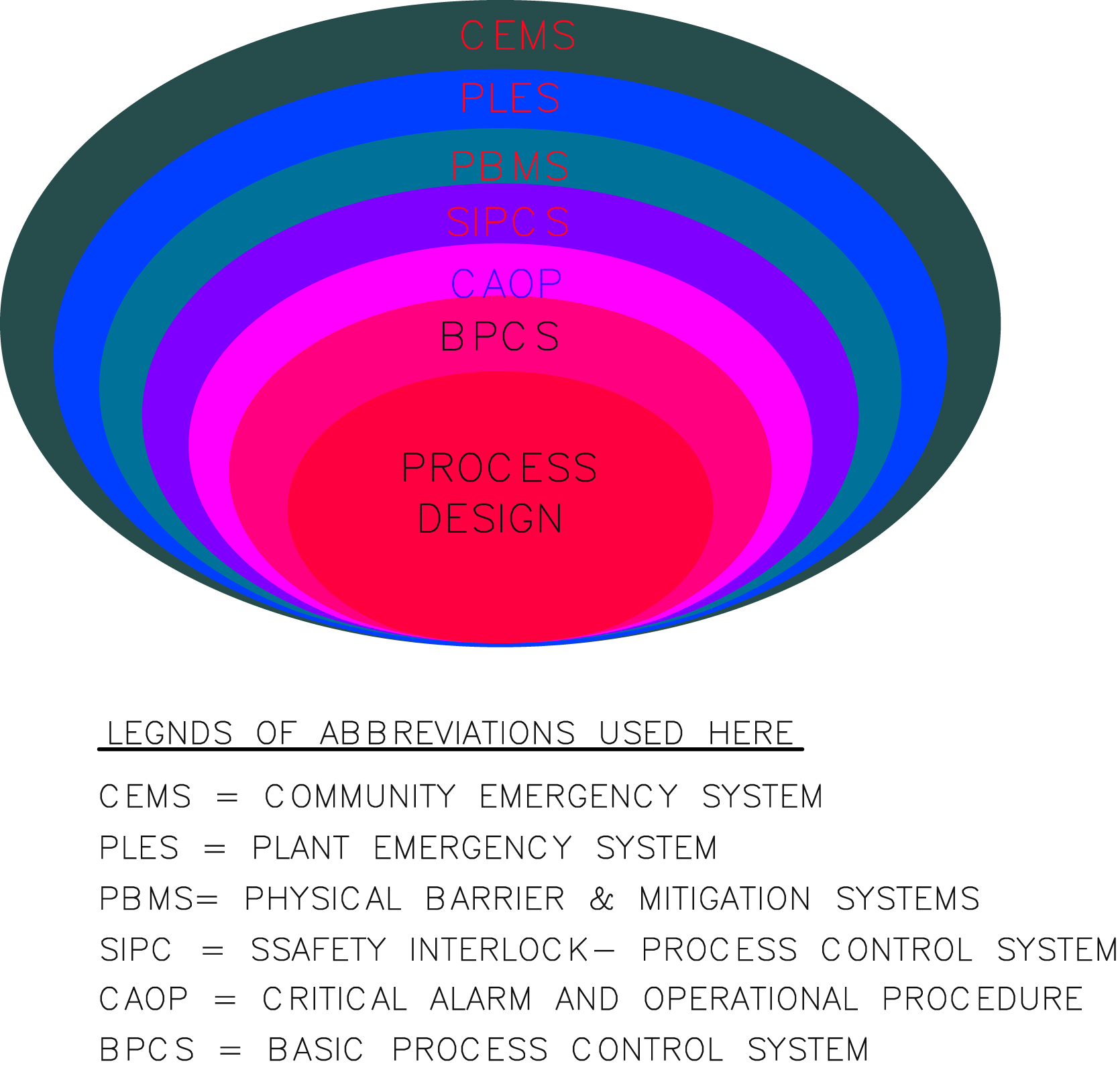
4.5. Control Measure
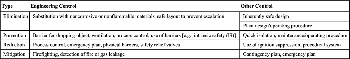
4.5.1. Control Measure Characteristic Features and Associated Details
Table II/4.5.1-1
| Type | Engineering Control | Other Control |
| Elimination | Substitution with noncorrosive or nonflammable materials, safe layout to prevent escalation | Inherently safe design |
| Plant design/operating procedure | ||
| Prevention | Barrier for dropping object, ventilation, process control, use of barriers [e.g., intrinsic safety (IS)] | Quick isolation, maintenance/operating procedure |
| Reduction | Process control, emergency plan, physical barriers, safety relief valves | Use of ignition suppression, procedural system |
| Mitigation | Firefighting, detection of fire or gas leakage | Contingency plan, emergency plan |
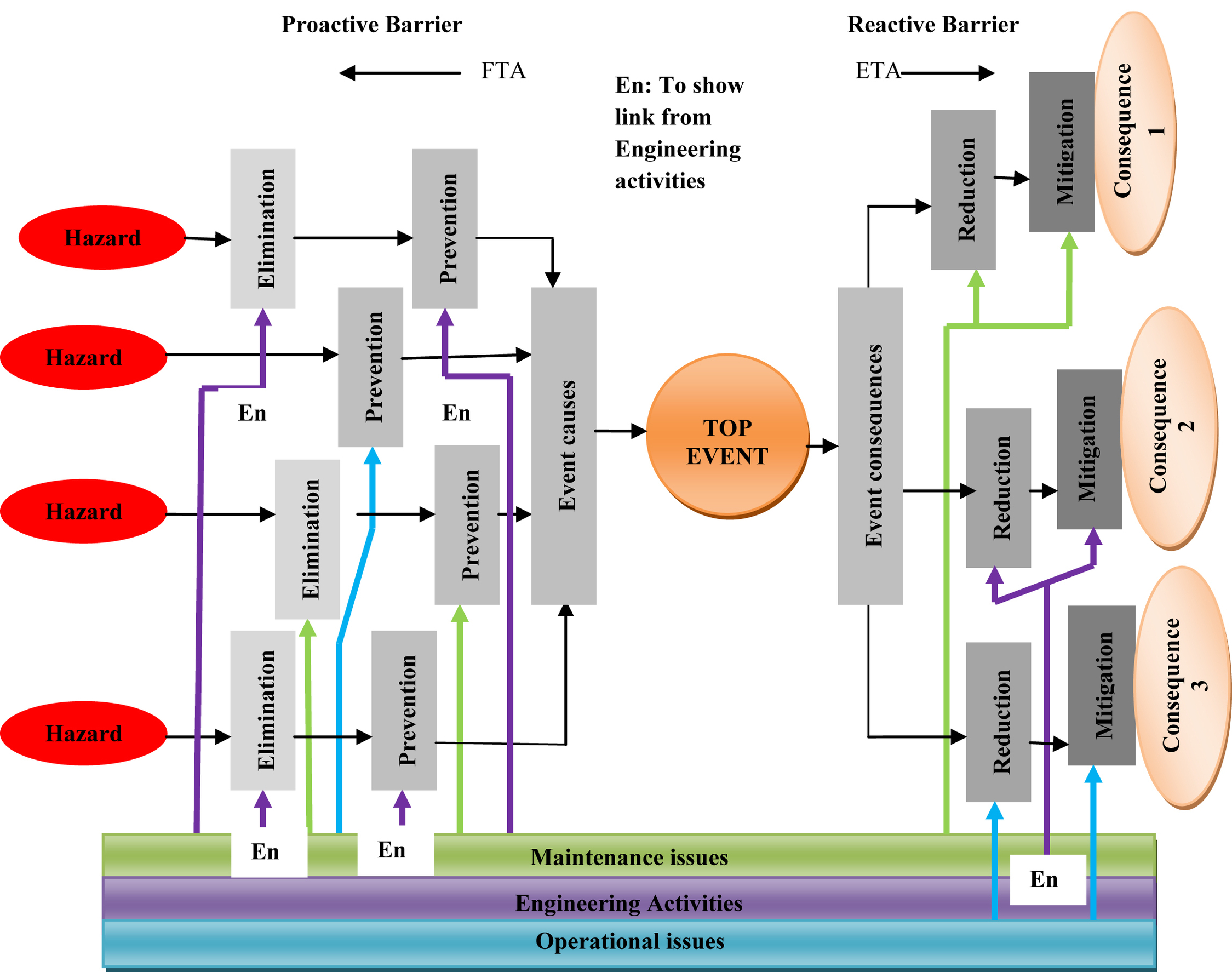
4.5.2. Various Control Measures
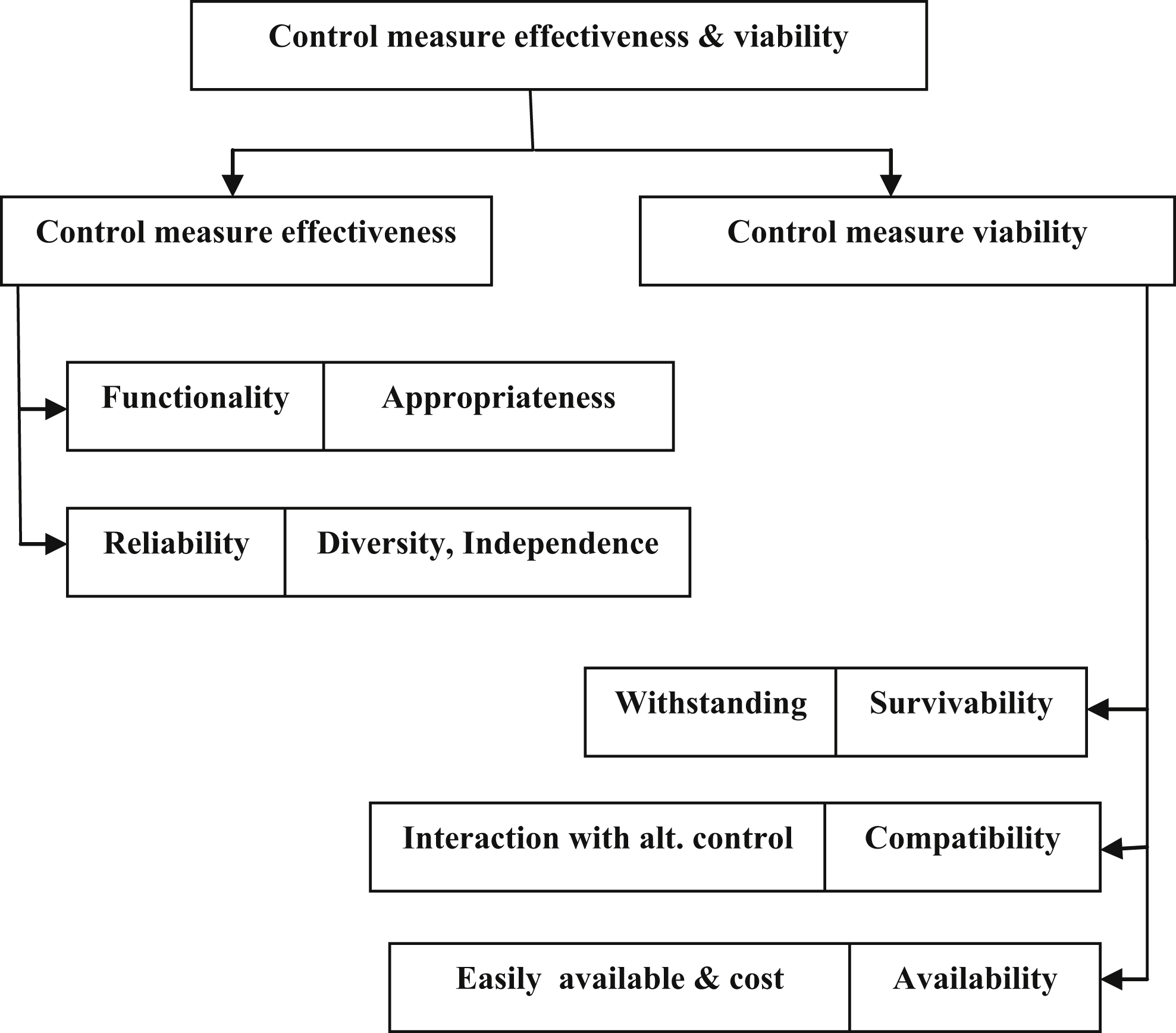
4.5.3. Influencing Factors Related to Selections and Effectiveness of Control Measure
4.5.4. Selection, Rejection, and Adequacy of Control Measure With Addition Controls

4.5.5. Performance Indicator and Standard
4.5.6. Additional Control Measure
4.5.7. Control Measure Output
4.5.8. Discussions
4.6. Safety Management System
4.6.1. Features
4.6.2. SMS and Control Measures
4.6.3. Operational Aspects in SMS
4.6.4. MOC
4.6.5. SMS Performance Standard
4.7. Conclusion

List of Abbreviations
| ALARP | As low as reasonably practicable |
| BFP | Boiler feed pump |
| CCPS | Center for chemical process safety |
| CEI | Chemical exposure index |
| COP | Critical operating parameter |
| DOW FEI | Dow Fire and Explosion Index |
| EC&I | Electrical, control, and instrumentation |
| ETA | Event tree analysis |
| FCV | Feed control valve |
| FEED | Front end engineering design |
| FMEA | Failure mode and effect analysis |
| FSA | Formal safety assessment |
| FTA | Fault tree analysis |
| HAZID | Hazard identification |
| HAZOP | Hazard and operability study |
| HC | Hydrocarbon |
| HRA | Human reliability analysis |
| HW | Hardware |
| IPLs | Independent protection layers |
| LOPA | Layer of protection analysis |
| MEA | Major accidental event |
| MF | Material factor |
| MHF | Major hazard facility |
| MHI | Material hazard index |
| MOC | Management of change |
| NOPSEMA | National Offshore Petroleum Safety and Environmental Management Authority |
| O&M | Operation and maintenance |
| OPGGS | Offshore Petroleum and Greenhouse Gas Storage (Safety) Regulation (Commonwealth) |
| OSHA | Occupational Safety and Safety Administration (USA) |
| P&ID | Piping (process) and instrumentation diagram |
| PFD | Process flow diagram |
| PHA | Plant hazard analysis/preliminary hazard analysis |
| PSF | Performance shaping factor |
| PSM | Process safety management |
| QRA | Quantitative risk analysis |
| SFARP/SFAIRP | So far as is reasonably practicable |
| SHI | Substance hazard index |
| SMS | Safety management system |
| SW | Software |