3.0. Field Sensors for Safety Instrumented Systems
An SIS is a collection of SIFs, each of which is one or more components designed to execute specific safety-related tasks designed to bring an industrial processes to a safe state in the event of hazardous conditions. One major issue of SIS is to balance and optimize two different parameters, viz. maximization of facility safety (against), maximization of economic benefit. A safety system needs to provide reliability for the intended protective function, at the same time ensuring higher operational availability of the process itself.
Another important issue one should keep in mind that the safety data provided by manufacturers for their devices, with due validation by a third certifying authority are laboratory results. Laboratory safety data, provided by manufacturers may be useful predictor safety data pertinent to control system but real world installed safety is always much worse. “Proven-in-use” data includes real-world failure causes; however it tends to be conservative, as it must cover the whole range of the category, from 20-year-old pneumatics to the latest smart technology [7].
3.0.1. Choices for Sensor Types
Instruments/sensors for SIS are separate and distinct from those used for BPCS, to ensure an independent layer of protection safety. In modern SIFs, continuous process transmitters in conjunction with comparator circuits are used for hazard detections, in places of process switches. The ability to easily change set point, better diagnostic capability, and continuous health checks make process transmitters better suitable and first choice for users. A “healthy” transmitter show changing output signal; in contrast to that, process switches provide no indication of “healthy” operation. So, when a process switch needs to change states at set point, it might also be failed and incapable of registering a dangerous situation! It indicates that process switches suffer from covert (hidden) failure. Basic purpose of diagnostics is to detect covert failures as overt (detected) failure. Since smart transmitters can be provided with diagnostics so also it is preferred in SIS applications.
3.0.2. Redundancy and Voting of Sensors
In SIS applications, importance of reliability and availability cannot be overestimated. In such cases, redundant transmitters may be deployed in 1oo2, 1oo3, 2oo3 or 2oo4 (typical for nuclear plants). Out of these, 2oo3 is a very good and common choice but voting of sensors in 2oo3 architecture demands special attention. High, low, average, and median are typical selection criteria for “voting” modules. The following may be considered as a guideline for selection of voting circuits for different kinds of applications in dangerous/hazardous conditions or events (from safety point of view):
• High selection: Larger measured value in the hazardous condition.
• Low selection: Smaller measured value in the hazardous condition.
Thus with above approach, 2oo3 reduces to 1oo3. Now, average selection is rather problematic, especially when one of the redundant transmitters happens to fail in the “safe” direction, making skewing (e.g., if 2, 3, 4 units are three values, average is 3 units now dangerous situation is say >4.5, then if the third transmitter fails then average would be 2.5 so going away from dangerous value). The median select criterion is very useful in safety systems because it effectively ignores any measurements deviating substantially from the others and is effective 2oo3 selection. Median value selection is also possible for discrete switches and/or for O/P of comparator circuit of transmitter.
3.0.3. Field Device Diagnostics and Its Impact
The concept of device diagnostics to diagnose overt and covert component failures has undergone sea changes in the present days. Apart from monitoring own performances, smart instruments are capable of predicting a great deal of information about what's going on with a process, well beyond the specific variable measurement or control. Some smart instruments are able to detect deterioration in a key component or realize sensor drift. Others look at the process and might spot changes, for example, differential pressure sensors can measure process noise and determine the normal level. Today's smart instrument can send a warning when they begin to notice such changes. Powerful diagnostic information is now available to optimize overall operation and maintenance. A similar model has been shown in Fig. IX/3.0.3-1.
(1) The lowest level with individual field devices diagnostic information. (2) Groups of individual loops working together to provide basic functions. (3) It is the operational level. (4) Based on above information, one can optimize overall operation and maintenance effectively at level 4.
From a safety point of view, these are very effective in the sense that smart devices now have sophisticated diagnostics, and are able to predict when a problem was developing, such as an impending component failure or sensor drift. Some diagnostic functions monitor and record the amount of force necessary to close a valve or the amount of time spent in any given position or voltage problems, etc. So, it is possible for the operating personnel to get insights into the process in their dashboard (beyond the basic process variable). Now with developed communication and networking with fieldbus, it is possible to send information to the control or asset management systems. These are achievable with the help of less expensive programmable electronics.
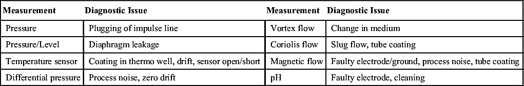
Some of the specific issues related to field devices are as given in the Table IX/3.0.3-1.

Figure IX/3.0.3-1 Smart device diagnostic information for overall performance. Developed inspired by A. Ajmeri, Smart Instruments and Device Diagnostics: How Well Is Your Plant Using Information, Yokogawa; Plant Services, March 2015; http://www.plantservices.com/articles/2015/smart-instruments-and-device-diagnostics/.
Table IX/3.0.3-1
Diagnostic Prediction of Measurement Problem
| Measurement | Diagnostic Issue | Measurement | Diagnostic Issue |
| Pressure | Plugging of impulse line | Vortex flow | Change in medium |
| Pressure/Level | Diaphragm leakage | Coriolis flow | Slug flow, tube coating |
| Temperature sensor | Coating in thermo well, drift, sensor open/short | Magnetic flow | Faulty electrode/ground, process noise, tube coating |
| Differential pressure | Process noise, zero drift | pH | Faulty electrode, cleaning |
3.1. Technical Issues for Sensors
There are a few important technical issues need attention of designers. Some of the pertinent issues have been addressed in the following clauses.
3.1.1. Factors Influencing Selecting Sensors
It is needless to argue that measurements affect the safety of a measurement loop. Therefore, it is important to look into the pertinent issues, listed as follows, which influence selection of sensors for various measurements:
• Use of transmitters, not process switches (Clause: 3.0.1)
• Common cause strength
• Diversity
• Built-in diagnostics
• Redundancy and availability
The reason for selection of transmitters in place of process switch and issue related to redundancy already discussed in Clause: 3.0.1 and 2. High ambient temperature may be a common cause; to combat against the same following issues may be considered:
• Robustness: To use robust transmitters (to protect electronics from high temperature)
• Installation: Install away from hot point
• Diagnostics: Suitable software to predict failure due to high temperature.
Diversity is an important point to eliminate CCF. Redundancy with instruments and devices using different technology is very useful for CCF or for minimizing the risk that a single failure mode will affect both. Of course, the diverse, backup technology should be strongly resistant to the failure modes that affect the primary technology. So, diversity in technology may be used, for example, for level measurement differential pressure transmitter and displacer type may be deployed in redundant mode so that higher availability as well as due to diversity, CCF will be less. This is true, provided the difference in sensitivity and response time of two types of instruments are suitably taken care of. The key issue always is safety return on investment (ROI), hence balancing between safety and life cycle cost.
3.1.2. Factors Influencing Performance
The following issues are a few examples of factors that influence performance of sensors, therefore need proper attention:
• Transmitter performance: Mere overall accuracy and other details may not be sufficient. Designers need to take care of many other data, for example, there may be loss of performance due to orientation change – positioning in tilted condition. A few other issues affect the transmitter performance shall include but not limited to: Ambient temperature variations, high static pressure, drifts, and stability. Drifts may be due to voltage variations, noise pick up, etc.
• Process interfaces: When there is plugging in the line, correct pressure is not reaching the transmitter, so even if transmitter is okay, the actual reading may be erroneous. Similarly if there is coating, thermowell or magnetic flow meter could not sense, and again produces erroneous result. In modern smart transmitters, separation of the sensor and electronics is possible, so the sensor may be directly connected to the process, with the electronics located at suitable place, this could sense such changes to reduce the effect.
• Sensor robustness quality control: Corrosion can cause overt failure of a process transmitter. Sudden overpressure in differential pressure transmitter can cause zero drift. Similarly, instrumentation practice is important, for example, if technician ignores the important role of equalizing valve, then sudden pressure may come on either side of a differential pressure transmitter causing damage (when without opening equalizing valve, either side valve is closed or opened suddenly). The last issue is related to maintenance practices. To circumvent these issues, robust sensors may be deployed.
3.1.3. Installation and Maintenance Issues
In order to have easy access earlier, transmitters are installed with long impulse line. This is no longer valid as modern transmitters are less prone to drift or fail (actual critical failure of hardware is around 15% and software 34%) and these can be accessed from control room via fieldbus. As more problem may be with impulse line so old concept needs change.
The user needs to quantify the calibration frequency based on its application for getting better results. The user can minimize their risk of sub-optimal selection, installation, and maintenance by working with suppliers who can bring to bear substantial measurement expertise and experience, and strong local technical support [7].
3.2. Safety Instruments Documentation
Standard specification sheets detailing measuring range, performance parameter, material specification, etc. are available in standard books and or from manufacturers’/engineers' documentation. Since the purpose of the book is safety applications, such standard documentations are not discussed here. If necessary, interested readers may go through [2]. Here, discussions shall be on various safety parameters for process transmitters. Naturally, during the discussions references will be made to standard process transmitter suppliers for data. Most of the parameters are extracted from renowned manufacturers. From the discussions it will be clear that in case of safety application, only authorized persons are allowed to handle the instruments, otherwise safety may be endangered. In this part, discussions will cover various symbols used, basic contents of the manuals, and various safety related parameters in brief.
3.2.1. Symbol Descriptions and General Instructions
There are a number of symbols (related to safety) used, and each of them has specific meaning or significance. Such commonly used symbols (related to safety) are listed in Table IX/3.2.1-1. Some of such indications may be as follows:
Warning: “I read this manual before working with the product. For personal and system safety, and for optimum product performance, make sure you thoroughly understand the contents before installing, using, or maintaining this product.” Or
Caution: “Product described in this document is not for use in nuclear application.”
Apart from the above symbols, at various places there will be following notifications in the manual. These are collected and reproduced here in brief; actual one may be more elaborative. Therefore, detailed instruction manual needs to be read and understood before handling the instruments even by authorized personnel.
• Authorized personnel: Only persons trained and having knowledge about the regulations are authorized to use and handle the instrument.
• Appropriate use: Each instrument is made for specific purpose and it should be used for the same. Operational reliability is ensured only if the instrument is properly used according to the specifications in the operating instructions manual as well as possible supplementary instructions.
Table IX/3.2.1-1
Symbols and Instructions for Instruments
| Symbol | Significance |
| Helpful additional information: Tips, note: | |
 | Caution: If ignored, there will be fault or malfunction. Warning: If ignored, injury to persons and/or serious damage to the instrument. Danger: If this warning is ignored, serious injury to persons and/or destruction of the instrument can result. |
 | Explosion applications. |
• Safety Label: Safety markings and tips must be followed.
• General safety instruction: The high tech device demands for strict following of instruction and guidelines mentioned.
• Safety instruction for oxygen use.
• CE conformity.
• NAMUR recommendations.
• Detailed product description:
• Configurations and commissioning tips
• Enabling and disabling operations
• Principles of operation
• Standard application details
• Standard installation details
• Mounting details
• Standard parts details
• Transportation and storage
• Connection details
• Wiring details
• Precautionary measures
• Setup and adjustments
• Set of program
• Saving of adjusted parameters
3.2.2. Functional Safety Details
Under this clause, various functional safeties and their interpretations will be discussed. Details given here are extracted from various safety instrument manuals of process instrument manufacturers of international repute, so that readers get the feel of actual data in use in various plant instrumentation.
• Manuals usually mention the certification details in the front such as “additional instructions for IEC 61508-certified device.
• SIL details in the transmitter body. There are various ways and means to describe SIL number in the transmitter. Some mention the same as last letter and digits in the model number of the transmitters in the name plate, for example, IA transmitter: “IGP10-T20D1F-M1S2;” last code “S2” indicates SIL option. Whereas in ABB transmitter identification of 266 (2600T series), pressure transmitter IEC 61508-certified are identified as “….The “Output” characteristic as per product datasheet is to be codified with digits 8 or T … Product Code with digit “8” (additional options required) and Product Code with digit “T” (no additional options)”. Also, the significance of SIL number is mentioned in the manual, for example, pressure transmitters certified according to IEC 61508 are suitable to be used in SIL2 applications as single channel, and in SIL3 applications with architecture 1oo2. It shows that there will be change in SIL application with changes in architecture, which was already discussed in previous chapters. This is true because for a single component, it is not correct to define a SIL level. SIL refers to the complete safety loop, and single device is designed to achieve the desired SIL level in the entire safety loop. Naturally with variations in architecture of the loop SIL requirements will change.
• Safety function: The instrument could be used in safety-critical applications to measure process pressure. If the process value is invalid due to an internal failure of instrument, the system is to go into safe/alarm state (NAMUR NE43 – taken from ABB 2600T) and the malfunction must be shown as warning message on the display (if applicable) and as a variation in the output.
• Miscellaneous other functional safety information in manual: The following are a few pertinent functional safety information found in instrument manual meant for safety:
• Management of functional safety including safety planning focusing on:
– Policies and strategies for safety achievement
– Safety life cycle activities, with responsible personnel
– Relevant procedures to life cycle phases
– Audits and follow-up procedures
• Safety information from plant owner:
– Overall safety life cycle information
– Applicable laws and standards
– System safety requirements
– I/O system response time
– System structure
– Safety requirement allocation
– Safety routine
The total system response time is determined by sensor detection time, logic solver time, and actuator response time, and this total time must be less than process safety time to get the safety.
• Design verification details: Third party certification and inspection report for compliance with IEC 61508:2010.
The safety parameters listed in the safety manual, the SIF designer SIL achieved using the PFDavg considering the architecture, proof test interval, proof test coverage, automatic internal diagnostic, repair time, and failure rates of the entire equipment are included in the SIF. The HFT must be checked and taken into consideration by the SIF designer to ensure that each subsystem within the SIF is in compliance with the minimum HFT requirements.
There are a few other functional safety details provided in the manual; these are:
• Installation:
• Environmental limits
• Mechanical installation and system completion
• Application limits
• System wiring
• Commissioning overall system
• Factory settings
• Output current limits (NAMUR 43 Standard—ABB 2600T)
• Overload condition (adjustable)
• Lower limit ≤3.8 mA
• Upper limit ≥20.5 mA
• Alarm current (adjustable):
• Lower set point <3.6 mA
• Upper limit >21 mA
• Faults outside the functional safety
• Operation details:
• System operating discipline
• Maintenance
• Preventive
• Routine
• Unit replacement
• Modification request
• MOC
• Process
• Procedure
• Documentation
• Training requirements
• Proof testing
• Error messages
With these functional safety requirements in mind, now discussions shall be on various safety and reliability related parameters important for SIS applications.
3.2.3. Safety and Reliability Data
Some safety and reliability data from internationally reputed manufacturers have been presented to note the type of data and the range of data normally associated with safety sensors.
• Safety data: The following are some of the safety data:
• Safety accuracy: 1–2%
• Response Time: 750 ms (maximum)
• Damping set to 0 s
• Updates: Every 50 ms
Notes associated with these data may be presented as warning with suitable symbol mentioned above.
Note: WARNING to ensure safe fault monitoring, the DCS should be able to detect fail high and fail low conditions as malfunction indicators.
• Reliability data: Failure data in line with IEC 61508 has been presented in Tables IX/3.2.3-1–IX/3.2.3-3. Table VII/1.3-1 may be referred to for legends of failure symbols.


There could be another type/way as shown below Table IX/3.2.3-2 (see Chapter VIII also).
PFDavg may be specified in the manual, for example, 1.6E-3; proof test interval:1 year (The PFH for single transmitter is 1.87E-7.) or PFDavg may be presented in the certificate with associated proof test interval (see Chapter VII) as shown in Table IX/3.2.3-3.
Manufacturers also specify useful lifetime of components contributing to λDu; (viz. in IA transmitter of Invensys). Also suggested preventive maintenance details such as periodic proof testing procedure are included as a part of the manual.
Like sensor alarm annunciation also play a major role in safety instrumented system as protection layer. Now focus will be on alarm systems.
..................Content has been hidden....................
You can't read the all page of ebook, please click here login for view all page.