Chapter IX
Safety Instrumented System Requirements for Fieldbus and Control Components
Abstract
Safety instrumented systems (SISs) component failure rate is extremely important for discussions on SIS components. In modern SIS, safety instrument function (SIF) components are connected by safe fieldbus, so detailed discussions on the requirements of safe fieldbus have been covered. The discussions also encompass details about EDDL, FDT, and various requirements of FF, PI OPC and HART so that FDI is possible. Alarms in SIS are important because it forms an IPL, therefore detailed discussions on alarm life cycle and alarm realization along with alarm management has been covered. Various technical aspects of sensors are also important part of SIF. Safe PLC is a requirement of SIS, so now the same can be realized has been covered. Also discussions on pros and cons of integration of BPCS and SIS via safe PLC have been covered. Final element which is the most vulnerable in SIS have been discussed at length with special reference to partial stroke testing full stroke testing and smart digital positioner. The chapter will be helpful in understanding the entire SIF loop thoroughly.
Keywords
Alarm life cycle and rationalization; Electronic device description language (EDDL); Field device integration (FDI); Field device tool (FDT); Full stroke test (FST); Integrated safety instrumented systems; Partial stroke test (PST); Safe fieldbus; Safe programmable logic controllers; Smart diagnostics; Smart positioner
1.0. General
On account of the presence of dangerous materials like flammable gases and corrosive chemicals, many industrial plants inherently are involved with varying amount of risk. In some plants, like (say) boilers where there may not be much involvement of hazardous materials yet due to mal or wrong operation, there are possibilities of hazard, for example, hazard due to CO formation in furnace due to incorrect operation in oxygen deficient atmosphere. Safety instrumented systems (SISs) are specifically designed to protect personnel, property, and the environment by reducing the likelihood or severity of impact in a hazardous event. Also, SIS is supposed to take the system to a safe state to avoid an accident. Each year, fires and explosions cause loss of huge property in various plants. Also such hazardous situations cost human life, loss of property, degradation of environment, and huge expenditure as litigation charges and compensation. So, corporate managements recognize the financial rewards of utilizing a properly designed process system that optimizes reliability and safety. The increased capability of modern instrumentation coupled with huge costs as result of industrial accidents compelled SIS to a new level of breadth of application especially in light of IEC standards for safety (61508 and 61511). Major challenges could be the balance between attending the maximum safety and making the same economically viable.
It is one of the functions of SIS to see that such flammable/toxic materials are isolated in during hazardous events. SIS consists of a number of safety instrument functions (SIFs), which call for safety integrity as per the international safety standards. SIL achievement in accordance with the requirements of IEC 61508 is required to be demonstration for each SIF. From previous discussions in Chapter VIII, it is clear SIL is dependent on:
• Architectural constraint: Associated factors: Safety failure fraction (SFF) and hardware fault tolerance (HFT)
• Target failure measure, expressed in PFD (probability of failure on demand)/PFH (probability of failure per hour)
• Systematic capability: Each element or component carrying safety function and methodology.
For any safety loop comprising several components, the safety integrity level (SIL) achievement is a joint responsibility of end-user and supplier, as will be clear from Table IX/1.0-1. Why discussing this here? These are discussed here to show that equipment manufacturer/system integrator or end-user is not only responsible for the same in isolation. In a safety life cycle, there are several phases involving several activities. So, at various stages there will be involvement of either end-user or supplier/manufacturers. The same issue has been elaborated in Clause 1.0.1; refer to Fig. IX/1.0-1 also.
Table IX/1.0-1
Phase-wise Responsibility of End-user and Supplier
| Phase | Responsibility | Activities |
Pre-design Phases 1–5 & 9 | End-user | Hazard identification, specify requirements, & setting up target SIL |
Design & installation Phases 6–8, 10–13 | Manufacturer/supplier | Development as per requirements and get target SIL |
O&M Phases 14–16 | End-user | Operation, maintenance, modification, & SIL maintenance |

1.0.1. Process/Plant Safety Requirement Specification Details
When one concentrates on IEC 61511-1:2003 (Clause 10.3), one would find that the standard specifies safety requirements, and the following are some of these safety requirements for SIF/SIS:
• All SIFs required for the required functional safety
• The extreme environmental conditions
• Major interferences such radio frequency interference, electrostatic disturbance, etc.
• Electrical area classifications
• Identification of process safe state for each of these SIFs
• Demand and demand rate for each SIF
• SIL and associated mode (continuous/low demand) of operation for each SIF
• To check the interaction of concurrent occurrence of safe states (e.g., multiple relief to flare)
• Requirements towards common cause failure (CCF)
• Requirement for proof-test intervals
• Response time requirements related to process safe state
• SIS process measurements and control with set point
• Functional and logical relationship between process input and output
• Various process operating/permissive conditions
• SIS process output actions
• Shutdown requirements (manual and auto protection)
• Resetting requirements after shutdown
• Energize or de-energize to trip logic
• Allowable spurious trip rate (maximum)
• Desired response from SIS on failure modes
• Interfaces between the SIS and other systems
• Various modes of plant operation and associated instrument function for each SIF
• The application software safety requirements IEC 61511-1:2003
• Requirements for overrides/inhibits/bypasses related to safe state maintenance
• MTTR for SIS taking all issues
• Avoidance of dangerous combinations of output for SIS
• Operational procedures
• Safety instrumented function necessary for survival in major accident
• Extreme environmental condition
1.0.2. Component Related Issues
As the title of the chapter signifies, in this part discussions will be on various components. According to the OREDA-97 report – well recognized in the world, 92% of the time these failures were due to the non-performance of their safety function upon demand by the sensors and final elements. Even if one looks from a conservative perspective as per Fig. VIII/1.0-1, at least 85% of faults are due to failed device. In modern automation systems, most of these field devices sensors and final elements are smart devices, and they are connected to the logic solvers with the help of fieldbus systems for some obvious reasons (discussed later). Naturally, these fieldbus systems need to be safe fieldbus systems. Therefore, in addition to the discussions on sensors, logic solver, and final elements, it is also necessary to address safe fieldbus systems to complete the discussions. According to IEC 61511, there are two groups considered. One is programmable electronics (PE) (mainly logic solver), the other is non-PE devices or equipment. Here there is a point to be noted; currently most of the instruments are smart, so they fall into type B instruments category (already discussed Clause 1.4 of Chapter VIII). There are two options for end-users to select field devices (sensors and final elements):
• Components selected in SIL application in accordance with IEC 61508-1 and 2.
• To cater to the requirements of IEC 61511 (11.4 and 11.5.3 to 11.5.6).
The difference between the two selections is based on who is to bear the responsibilities for the burden of proof. This is clear from Fig. IX/1.0.2-1.
From the preceding figure, it is clear that in case of prior use, referenced in IEC 61511, it is the user who is responsible.
However, here details presented mainly concentrate on sensors and final element in their generic terms.
1.0.3. Safe Fieldbus (FB)
Fieldbus is more than just a network and a digital replacement for 4–20 mA technology. The same fieldbus system, with additional technological developments, is used in safety application under the name of safety fieldbus system. For this reason, Erich Janoschek of TÜV Rhineland, describes a safety fieldbus system as “a safety fieldbus network as a specialized mail messaging process.” On account of clear advantages of fieldbus system, the entire industry connected to modern instrumentation systems is highly impressed and interested towards use of fieldbus systems in safety applications also. Major advantages of fieldbus and safety fieldbus systems are [2]:
• Easy to use, and easy future expansion and modification.
• More extensive data exchange to and from the field devices at a much faster rate.
• Improved diagnostics.
• Reliable, space-saving, cost-effective, and deterministic.
• Greater flexibility in system design, space savings, and layout.
• Openness and interface capability makes it possible to integrate multiple products from different vendors in a system.
• Increased uptime and plant utilization resulting from improved asset management.
• Improved maintenance and test data for reporting.
Nearly 90% of the causes for failure are due to field devices. Naturally, checking the health of the I/O, field devices, and valves are obvious. The system should also incorporate capabilities, such as sensor validation and environmental condition monitoring for conditions that can cause sensor degradation, and monitoring of impulse line blockage. All these are possible with the help of a safe fieldbus system. Safe fieldbus technology is a unified infrastructure to manage data, communication, plant assets, and plant events while providing highly distributed control functionality and interoperability between devices and subsystems. For safety protocol transmission, it is important how it is sent and received in a corruption-free way rather than the medium itself. So what is more important is the safe field bus technology. System integrity ensures that the running safely, with maximized reliability and a proactive maintenance strategy. In an emergency hazardous situation, the system shuts down in a logical and controlled manner with avoidance of the creation of waste, loss to the facility, and damage to personnel and the environment. At the same time, it is important to avoid spurious/nuisance trips, which has negative effect on production. To manage the show, it is at times important to have global access to the process data. At the same time, well-secured data should be presented in a manner that is easy to understand and act upon. Open, scalable integration addresses the need to drive out custom integration costs and the requirement for best of breed applications to work seamlessly together in an open environment. As an open automation infrastructure, safe fieldbus technology addresses all of these requirements in several different ways [4].
1.0.4. Sensor
Field sensors are used to collect information necessary to determine if an emergency situation exists. The purpose of these sensors is to measure process parameters (e.g., temperature, pressure, flow, etc.) or monitor the process condition/status, used to determine if the equipment or process is in a safe state. Sensor types range from simple pneumatic or electrical switches to smart transmitters with on-board diagnostics. These sensors in some applications are dedicated to SIS. Manufacturers’ approach, in line with IEC 61508 towards the development of sensor, shall include but is not limited to the following:
• Development of safety requirements based on end-user specification
• Instrument hardware and architecture design as per standard-part 2 rule
• Software control verification validation in line with standard-part 3
• Diagnostics and verification of the same
• Manufacturing controls to ensure to the desired safety requirements
• Control of management of change (MOC) to meet the requirements
• Failure modes, effects and diagnostic analysis (FMEDA) to determine SFF, PHF
• Details of proof test requirements
• Get third-party certification as per functional safety assessor (FSA) discussed in Chapter VIII
• Development and issuance of safety manual
Normally, manufacturers notify the certifying authority regarding the issuance of the certificates. The certifying authority checks that all the requirements of the standard are met (see Clause 1.4 of Chapter VIII), and issues the certificates. As per IEC 61511, users can develop other criteria for certifying SIS loop components including requirements for the selection of components and subsystems based on prior use (Clause 11.5.3 of the standard). The main issue here is the “appropriate evidence” for subsystems and components that these are suitable for safety instrumentation. The standard also specifies the required documentation pertinent to the following issues mainly (see Clause 1.4 of Chapter VIII):
• Manufacturers
• Quality
• Configuration management
• Adequate specification and identification of components
• Hardware/software identification
• Awareness evaluation by end-user for when modification is done by manufacturer
• Demonstration of performance of subsystem/components (proof)
• Similar operating profile
• Physical environment
• Volume of operating experience
• Update and monitoring
• Addition with proper experience
• Removal when non-satisfactory performance is reported
However, there is significant value to the end-user for the product “designed as per IEC 61508.”
1.0.5. Logic Solver
The purpose of a logic solver, as a component portion, I/O signal processing unit, main sets of processors pertinent to SIS, determine the actions to be taken based on the information gathered. Highly reliable logic solvers can provide both fail-safe and fault-tolerant operations. A controller reads signals from the sensors and executes pre-programmed actions to produce output to final elements for preventing a hazard event from happening. Logic solver subsystems include but are not limited to the following:
• Processor/memory units
• Communication processors (as applicable)
• I/O signal processing boards
• Peripherals:
• Human machine interface (display)
• Printers/loggers
• Link interface
• Gateways/network support switches
• Termination units
• Racks, cabinets
• Power supplies system
• Gateways/network support switches
• System software:
• Software libraries
• Programming tools
• Communication protocols
Suitable safety manuals shall be there to help utilizing the facilities. When there is any non-certified equipment, then the PFD calculations are necessarily performed to show the contribution of such logic solver is within acceptable limit. Whereas for certified item pre-calculated and verified data are made available. For software applications, V model of the standard needs to be followed; for this Fig. VIII/2.0.3-2 may be referenced. In case of non-certified systems, necessary precautions shall be taken to ensure safe communication, which is well-documented and verified in case of certified systems. For SILs above SIL1, certified relays, safety solid state, and safety programmable logic controllers (PLCs) would be necessary. Really to achieve SIL3, redundancy in safety PLC is necessary. For existing systems, it is not possible to replace the entire systems with a new certified logic solver. In that case, a few issues need to be addressed:
• Hazard analysis to check whether existing safety functions are covered; if not, to find the reasons and get the ways.
• Study isolation between safety functions and basic plant control system (BPCS) except for low-risk cases where this may not be suitable.
• To check and document proof test procedure and set proof test interval. Suitable measure towards this is necessary.
• Record of failure rates from maintenance, etc.
Many industries used to maintain separation between the process controls and safety systems; however the latest edition of the standard does not specify the same in black and white. So, some integrations and interconnections between the systems are seen. For such integration/interconnections, special measures shall be implemented to avoid adverse effects between SIS and non-SIS systems, or between various SIS and applications. If suitable special measures are implemented, a limited degree of interconnection can be allowed.
1.0.6. Final Elements
Not only because final elements contribute 50% of PFD share, but also final control elements are the key components of any control loop in any system, be it BPCS or SIS. Therefore selection of final elements needs special attention. Final element implements the action determined by the logic system. This final control element of interest to SIS is typically a pneumatically/hydraulically actuated on-off valve operated by solenoid valve(s). But it could be other types also. It is important to keep in mind the applicability SIL assignment to final elements. When needed, assignment criteria may be applied. Using perspective of IEC 61508 and 61511 same assignment criteria could be fixed.
From the discussions, it transpires that each element of safety loop contributes to PFD for the safety loop. Naturally, PFD from the valve or final elements needs to be considered for SIL. This is very easy simple statement. One needs to look into the issue slightly in depth. From use point of view there can be mainly three pattern of usage of final elements, such as:
• Single element used for process control under safety system (on/off)
• Single element in normal conditions modulates under BPCS and for safety controlled by safety system through safety interlock
• Two sets of valve one for modulating control under BPCS another for safety under SIS
In the first two cases, failure of the final element places demand on SIF so it is needless to tell this calls for SIL rating. In the third case, final element under BPCS provides additional hardware fault tolerance for higher SIL application. To the end-user, here mean time to fail (MTTF) data is important to determine SIL level. Thus it is clear why SIL is important for final elements, which in fact is not restricted to valve damper, but could be anything such as circuit breaker, etc. also. So, for each application, suitability of the same is important for consideration. Major issues related to selection of final element selection shall include but are not limited to the following:
• Type: As suitably applicable for the application
• Architecture in line with IEC 61511-1:203 clause number 11
• Control design: Locking arrangement to avoid unauthorized operation
• Partial stroke test as functional test
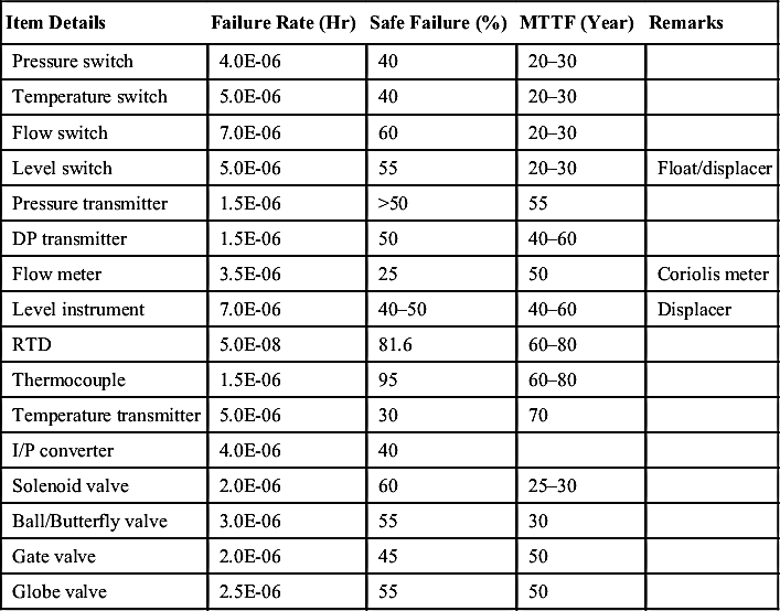
1.0.7. Typical Failure Data
The data presented here are typical values only. Actual data needs to be collected. The data given here in Table IX/1.0.7-1 is for the reader to get an idea about the issue. Major sources of these data are from Refs. [1] and [3], and balance data are from the plant data collected.
Table IX/1.0.7-1
Typical Failure Rate for Some Common Field Devices
| Item Details | Failure Rate (Hr) | Safe Failure (%) | MTTF (Year) | Remarks |
| Pressure switch | 4.0E-06 | 40 | 20–30 | |
| Temperature switch | 5.0E-06 | 40 | 20–30 | |
| Flow switch | 7.0E-06 | 60 | 20–30 | |
| Level switch | 5.0E-06 | 55 | 20–30 | Float/displacer |
| Pressure transmitter | 1.5E-06 | >50 | 55 | |
| DP transmitter | 1.5E-06 | 50 | 40–60 | |
| Flow meter | 3.5E-06 | 25 | 50 | Coriolis meter |
| Level instrument | 7.0E-06 | 40–50 | 40–60 | Displacer |
| RTD | 5.0E-08 | 81.6 | 60–80 | |
| Thermocouple | 1.5E-06 | 95 | 60–80 | |
| Temperature transmitter | 5.0E-06 | 30 | 70 | |
| I/P converter | 4.0E-06 | 40 | ||
| Solenoid valve | 2.0E-06 | 60 | 25–30 | |
| Ball/Butterfly valve | 3.0E-06 | 55 | 30 | |
| Gate valve | 2.0E-06 | 45 | 50 | |
| Globe valve | 2.5E-06 | 55 | 50 |
Now with these basic ideas in mind, it is time to go for little details into each system components and subsystems. Starting with safe fieldbus system, discussions will be presented on field instruments, alarm systems, logic solvers, and final elements also in sequence.
..................Content has been hidden....................
You can't read the all page of ebook, please click here login for view all page.