
1.0. Safety Requirement Specification
From a health and safety study report in the United Kingdom, it has been found that, of the total number of accidents involving control systems, 44% resulted from specification-related issues, 15% from design and implementation issues, 6% from installation and commissioning, 15% from O&M issues, and 20% from changes after commissioning (indicated anticlockwise in the figure).
From the percentage failure contribution diagram in Fig. X/1.0-1 it is clear that the development activities for specification need special attention. First, we shall look at how a system specification is developed from system requirement definitions, then we shall look at the requirements for a safety system, that is, SRS.

1.0.1. System Specification Development
Defining requirements to establish specifications is the first step. It is necessary that requirements are established in a systematic way to ensure their accuracy and completeness. Requirements and specifications are very important components. There is a difference between “requirements” and “specifications.”
• Requirements: A requirement is a condition needed by a user to solve a problem or achieve an objective. After a thorough study, user's requirements should be clarified and documented to generate the corresponding specifications. For establishing the requirements, the following brief discussions are helpful and important.
Discussing requirements with the customer is very important. Without agreement between the customer and the designer, requirements cannot be established. Ambiguous requirements can be caused by missing requirements, ambiguous words, introduced elements etc. It is better to remove any ambiguity at the earliest opportunity. One of the most important things is to ask questions. Context-free questions are high-level questions (e.g., what environment is this product likely to encounter and what is the tradeoff between time and value?). These questions are posed early in a project to obtain information about global properties of the design problem and potential solutions. Errors developed during the requirements or specifications stage may lead to errors in the design stage, so, when an error is detected, the engineers must review the issue to fix the problem as soon as possible. This may cost additional time but could indicate errors in assumption or other requirements.
• Specifications: A specification is a document that specifies, in a precise, verifiable manner, the requirements, design, behavior, or other characteristics of a system, and often the procedures for determining whether these provisions have been satisfied.
For establishing requirements and developing specifications, the appropriate people must be involved. A meeting should be arranged where a facilitator can help to resolve issues like conflicts, personality clashes, intergroup prejudices, etc. On account of the highly complex issues involved, the facilitator should possess knowledge from different engineering disciplines and possess experience in the area. So, people with high technical skills are necessary. Also good communication skills are necessary because of the exchange of information between the customer and the designer, and to settle various issues among participants. Therefore people with both technical and communication skills would be necessary for the establishment of good requirements. The following are the major steps necessary for establishing the correct requirements [11]:
• Ambiguity poll
• Technical review
• User satisfaction test
• Existing products
For a definition of system requirements the following points will be useful:
• Definition of mission: Identification and establishment of the primary operating mission along with alternative and secondary missions
• Parameters and performance: Defining operational characteristics and functional requirements
• Use requirements: Marrying system with user requirements
• System details: Quantification of equipment, personnel, area requirements, etc. and location details
Costing, failure rates, mean time between maintenance, maintenance downtime, the environment (environmental condition), etc. are major factors that affect the development of requirements of specifications. Fig. X/1.0.1-1 shows typical stages involved in developing specifications from the definition of requirements.

1.0.2. Functional Safety Challenges
In spite of the fact that almost all requirements for SIS in process and other industries are stated in the international standards, it is still challenging for engineers to justify and estimate investments in SIS during initial phases [1]. So, the frontend engineering and design team starts with a predefined SIS design when the process conceptual design is not well defined. A predefined SIS (architecture, technology, testing philosophy) could lead to a nonoptimal SIS design, that is, the SIS could be overdesigned or underdesigned. Thus this could be a starting point, but subsequently this needs to be corrected through a systematic approach toward developing a specification. As seen in Fig. X/1.0-1, a poor quality specification is responsible for major accidents. The two major challenges for SIS design are [9]:
• Reduction in random hardware failures
• Reduction in systematic faults
The former could be addressed by appropriate selection of equipment, while to address the latter a good quality specification needs to be developed. It has been found that 60% of SIS failures are embedded before commissioning and 85% of such faults are related to engineering. Therefore importance and requirements for a systematic approach in developing a specification cannot be overestimated.
1.0.3. Certified Functional Safety Experts
As per IEC 61511 one sees that “Persons, departments, organizations involved in safety life cycle activities shall be competent to carry out the activities for which they are accountable.” Therefore involvement of certified functional safety experts at an early stage is helpful in appropriate equipment selection and proper framing of specifications. With proper planning, companies can manage inherent operational risks and avoid production outages, property damage, environmental impact, and damage to personnel. Experts help to obtain certified hardware, software, field devices, and engineering services [such as development of SRS, safety instrument function (SIF) designs, and SIL verification calculations] needed to meet the requirements of the safety system life cycle.
1.0.4. Functional Approach Toward Safety Requirement Specification
In line with IEC 61511 the requirements of SIF, hence SIS, can only be determined after completion of the conceptual process design and process hazard analysis (PHA), as shown in Fig. X/1.0.4-1.

The system starts with project/process definitions and process conceptual design. The event history and application standards are applied to the conceptual design to obtain the process safety information. Now, the entire system is subject to PHA to obtain details about various consequences. After applying the available protection layer the situations are reassessed for SIF. As discussed earlier, target SIL assessments are also done. So, finally, all the following components form the SRS for SIS:
• Process safety information
• Potential hazard
• Consequence of hazard
• Available protection layer
• Target SIL
Tolerable risk guidelines actually help in deciding the SIF requirements and associated target SIL.
1.1. Safety Requirement Specification
According to IEC 615111:2003 (Clause 3.2.78) SRS is defined as “specification that contains all the requirements of the safety instrumented functions to be performed by the safety instrumented system” and the basic objective of the SRS is to specify all the requirements of the SIS to be utilized during detailed design and safety information systems. In this clause coverage shall be on the design engineering part, that is, requirements to design SIS to provide the necessary SIFs and meet SIL. SRS forms the basis for further planning for the design of SIS. Also because SRS includes the associated tests and test criteria, it also forms the basis for verification and validation. The implementation phase starts with the design and detailed planning of the SRS (and other measures) for reducing risk. Design and planning are followed by installation, commissioning, and validation of the plant.
Since different people work as per SRS during different phases of the safety life cycle, it is necessary that SRS is developed in an easily understandable manner. SRS includes the functional description of the safety functions as well as all the conditions that cause them to be triggered. In addition, determination of the SIL is part of the detailed consideration of each safety function.
The cause and effect method (see API RP 14C guideline) is one of the easier, proven, and extremely effective ways for the description of safety functions and shutdown conditions. No special programming knowledge is required for this. So, process specialists can also directly define their requirements. The causes are defined in the rows and probable effects are shown in columns. The linking of several causes and the definition of the relationship between causes and effects is carried out at the intersections of the rows and columns.
Fig. X/1.1-1 shows another way, where various system requirements and SIF requirements in conjunction with SRS inputs form SRS to get an SRS output. Now we shall look deeper into SRS and discuss how various inputs and requirements form SRS to establish details in the form of SRS output.

1.1.1. SRS Development Personnel
Who is responsible for development of SRS documentation? As safety is very much related with process, some think that this should be developed by a process contractor. It is better if it is developed by a team of engineers. As this end user is finally responsible for it so, it is better if it is initiated by the end user’s instrumentation engineer. There will be a great deal of information exchange and interaction on the issue, so the end user's instrumentation engineer needs to be involved to coordinate with in-house process engineering and the safety engineering department personnel. In addition, the SIS supplier engineering contractor and process supplier engineers should be involved in developing the SRS.
1.1.2. SRS Documentation
A number of documentations are generated for SRS development. However, the quantum of such documentations depends highly on the complexity of the project. So it is not possible to be precise about such documentations. However, generally, documentations under the following headings are usually generated in connection with SRS developmental activities [5–7]:
• Design details
• Architectural details
• Reliability study
• Hardware specification
• Software development details
• HMI details
• Installation and testing
• Operating procedure
• Maintenance requirements
All such documentations are developed for each SIF. There are three components or parts in SRS requirements and associated documentation, such as:
• General
• Functional
• SIL
So the basic format for SIS consisting of n SIFs can be conceived as shown in Fig. X/1.1.2-1.

1.1.3. SRS Input
These are general requirements or input necessary to develop SRS. These shall include but are not limited to the following:
• Process information details: Process description with well-defined scope and boundary and supported by relevant drawings is necessary to acquire the process parameters. Special/specific conditions for the process also need to be described.
• Regulations: Local/national regulations and international codes and standards under whose purview the facility falls must be included as it is necessary for compliance.
• Environmental condition: The environmental condition expected for the facility especially for extreme conditions should be mentioned.
• Operational modes: Various modes of operation of the plant/facility including normal and abnormal operations as well as startup/shutdown mode shall be included.
1.1.4. SIF Requirements
Based on clause 10.3.1 of IEC 61511-1:2003, the information listed here is mainly applicable for each SIF:
• List of all SIFs in SIS, along with description of SIF
• Unique name or ID for SIF
• Process description of SIF
• The required target SIL for SIF
• Demand mode and demand rate for SIF
• Safe state of the process for SIF: As per IEC 61511-1:2003 “state of the process when safety is achieved” (the description should address in detail the starting, stopping, or running of a stream, sequential shutdown, which valves to be operated, which flow to be regulated, etc.; this should also take into consideration human factors).
• Proof test interval for SIF: This is an important issue. Proof tests are meant to test the function as far as possible (could be dangerous in a shutdown condition). Major issues related to this shall include but not be limited to the following [12]:
• Description of the proof test procedure
• Precaution and safety to be under taken for proof test
• Required proof tests in life cycle
• Human aspect: Consequence because of wrong proof test procedure
• Documentation of proof test activity
• Process safety response time consists of three components:
• Process time constant and dead time in process response
• Electrical timing: Scan time of controller, or control system delay time
• Mechanical inertia
• Reset requirements for SIF
• Definition and clearance for bypass/inhibit/override for SIF
• Alarm and trip [3] details for SIF including:
• Architecture
• Number and type of input
• Measurement range
• Trip level
• Fail safe and fault tolerance for SIF
• Additional SIF requirements to describe how it works:
1.1.5. SIS Requirements
SIS requirements shall include but not be limited to the following. Also many of these will be determined from corresponding data of various SIFs under SIS:
• Dangerous combination of outputs
• SIS and other system interface
• Feasible mean time to repair (MTTR) for SIS
• Defined failure modes and response from SIS
• Sources of common cause failure (CCF)
• Response time of SIS for safe state
• Manual shutdown requirements
• Maximum allowable spurious trips
• Action to bring to safe state in case of fault detection
1.1.6. SRS Information
Based on the inputs discussed in Clause 1.1.3–1.1.5 an SRS shall be developed, which shall include at least the following information in line with IEC 61511-1:2003:
• Description of all the SIFs necessary to achieve the required functional safety
• Requirements to identify and take into account CCFs
• Definition of safe state for each SIF
• Definition of individual safe process state, which when it occurs concurrently may create a separate hazard (e.g., multiple relief to flare system).
• Assumed sources of demand and demand rate
• Requirements of proof test intervals
• Response time of SIS to bring the system to a safe state.
• SIL and mode of operation (on demand/continuous) for each SIF
• Description of process measurements and trip points
• Description of SIS process output action and criteria for successful operation
• Functional relationship among process input and output including logic, mathematical functions, and permission
• Requirements for manual shutdown
• Requirements for energize/deenergize to trip
• Requirements for resetting after trip [e.g., for purging in burner management system (BMS)] [5]
• Failure modes and desired response of SIS (e.g., first out alarm)
• Maximum allowable spurious trips
• Procedure for starting and resetting SIS (if any)
• SIS interface with other systems [e.g., with basic plant control system (BPCS), fire and gas system (FGS), etc.]
• Requirement, definition, and clearance for bypass/inhibit/override; to specify any action needed to achieve and maintain safe state for such actions human factors should be taken into account
• Application of software safety function as per IEC 61511-1: 2003 (Clause 12.2.2)
• Feasible MTTR taking into account location, spares, etc.
• Dangerous combination of outputs to be avoided
• Extreme environmental conditions (to take into account temperature, humidity, electromagnetic interference, radiofrequency interference, etc.) [4]
• Identification of normal and abnormal modes of operation and requirements to survive a major event
• Definition of SIF necessary to survive a major accident [8]
• Identification of security measure during hazard and risk analysis to prevent malevolent and unauthorized actions [8]
The discussions on SRS will not be completed until specific reference is made to software development. For software development, the IEC recognizes (Clause 12.2.2 of IEC 61511-1:2003) three types of software and three software languages as depicted in Fig. X/1.1.6-1.

1.1.7. Alarm Annunciator
The basic characteristics of alarm systems have already been covered at length in Chapter IX. Since an alarm is one of the most fundamental issues in a control system, it will be discussed here again in this context. In this clause, focus will be on independent alarm systems that can be applied to critical applications independently of a programmable logic controller/distributed control system (PLC/DCS). In spite of so much technological developments and modern instrumentation and control, because of the potential consequences to plant and personnel, “hard” alarms are still not only accepted but also considered as primary alarming functions and a backup to DCS and PLC strategies in critical emergency shutdown (ESD) and SRS (independent of PLC/DCS) in many industrial sectors/applications. One of the probable reasons could be that “soft” alarms can be susceptible to common-mode failures (in contrast to hard alarms). This is shown in Fig. X/1.1.7-1 where an alarm (and a trip signal) is generated from a transmitter with the help of a limit value monitor and is independent of PLC/DCS.
In view of the CCF effect, many feel that “soft” alarms may be inadequate in providing the degree of protection demanded for some critical applications. “Soft” alarms are based on scanning input whereas “hard” alarms provide continuous supervision of an individual process signal. In some fast-changing applications, the computer's scanning speed or network throughput time may be inadequate. Also “hard” alarms could be set very easily compared to soft alarms in which there is a need to understand programming and the programming errors that may occur. Alarms have a dead band (the difference between the set and reset point) and this can be adjusted easily in hardwired alarms. With a simple “cause and effect” action, limit alarms can be economically used in a wide variety of basic and complex applications [3]:
• Warn of a hazard with “hard” alarm when the signal goes beyond a set limit
• Create an independent trip system to avert central power failure or DCS shutdown

Figure X/1.1.7-1 Hardwired alarm for safety. DCS, distributed control system; ESD, emergency shutdown; LVM, limit value monitor; PLC, programmable logic controller; PS, power supply.
• Reliable without CCF and cost-effective
• Monitor parameter annunciates when parameter rate of change exceeds a selected rate.
There are various types of hardwired alarms in industrial use:
• Input fault alarm
• Rate of change alarm
• Self-diagnostic alarm
• Window alarm
• Average/differential alarm
• Fail safe/nonfail safe alarm
Most of these are standard alarms and details are available in any standard instrumentation book. When the average of two or three input signals exceeds a set point, an average alarm is generated. A differential alarm is generated when the difference between two input signals, such as two resistance temperature detectors (RTDs), exceeds a specific value. Fail safe and nonfail safe alarms [3] are clearly depicted in Fig. X/1.1.7-2. In the case of a fail alarm sensed by a normally closed contact as shown, the relay deenergizes. However, this also happens when power fails. So in a fail safe alarm it is also annunciated because power failure is not a normal condition. For this reason this is fail safe.
In the case of a nonfail safe alarm if power fails and during that period a fault occurs, the relay cannot operate to annunciate. So this is nonfail safe. These alarms are standard issue. With this, discussion on SRS is concluded and we can now move on to discussions on design and engineering.
1.2. Design and Engineering
Having completed SRS it is time to implement it. This implementation naturally starts from the design and engineering phase. Before tackling the technical details it is better to understand this phase with one hypothetical example of a tank-filling process, as discussed in Chapter VII (Fig. VII/1.1-3). To understand design implementation, Fig. X/1.2-1 may be referred to.
As stated in the banner of the figure, when the pressure inside the vessel, sensed by two pressure sensors (SIL2) in redundant mode, exceeds the set point, it will initiate the stopping of the feeding pump and close the supply line block valve with the help of a logic solver. Here, in the example, sensors, final elements, and the safety functions to be performed are all identified i.e., the logic solver. Minimum of five requirements are necessary discussed subsequently. Until now only three have been specified. Let the process be SIL3 safety and the process safe time be 6 s. It is common practice to consider half of process safe time as time of response for the safety system. Therefore the safety response time necessary is 3 s. So, all the minimum five requirements, namely, sensor, logic solver, final element, SIL requirement, and process response time, are specified. Here, sensors are redundant architecture (see Fig. VIII/1.3-2 for two SIL2 sensors in redundant mode equivalent to SIL3) and can be considered as SIL3. Fig. X/1.2-1 shows how SRS requirements have been translated into design engineering in implementing the requirements. The drawing also shows how the wiring has been done and how commands are issued. In the case of field bus application there will not be individual physical wiring exactly as shown in the drawing; instead in those cases, software implementation, that is, software communication, needs to be taken into account. In this example, details regarding the logic solver are missing. To look deeper into the logic solver and other components let us visit Fig. X/1.2-2 which shows much detailing about logic solver issues such as hardware/software/other integrating details. As stated earlier, in cases of SIS application it is better to deploy safe PLC, which is now offered by all major manufacturers as indicated in Fig. X/1.2-3. In the case of sensors and final elements, in addition to wiring, software communication details have been shown to take care of the field bus system, if any. Thus from the two examples an attempt has been made to establish how various requirements in SRS could be implemented in design and engineering. The two examples are meant to give the idea that at the design and engineering stage proper planning shall be developed to validate all SRS requirements and testing at every subphase. Now, discussions will be focused on various issues related to design and engineering systems—the first step toward implementation.

Figure X/1.1.7-2 Fail safe and nonfail safe alarms. C, contact; NC, normally closed; NO, normally open.

Figure X/1.2-1 Design implementation. MCC, Motor control center; SV, solenoid/shut down valve etc. Based on T.V. Capelle, M.J.M. Houtermans, Functional Safety: A Practical Approach for End-Users and System Integrators, HIMA Paul Hildebrandt GmbH Co KG, June 2006. White Paper.
1.2.1. Resources
Because this is the design phase, various vendors will be involved such as engineering consultants, process vendors, control systems, field equipment suppliers, etc. As per IEC, there shall be competent key personnel with defined lines of responsibilities from all concerned organizations. Those who are significantly involved must understand their responsibility in analysis, assessment, validation, or verification thoroughly; otherwise the results may be disappointing. In this connection, Part 3 of IEC 61508 may be referred to.


1.2.2. Planning
Planning is important in all phases of the safety life cycle. Proper planning is required to demonstrate that SIS is implemented as per SRS. Verification shall run parallel with validation, which starts after integration. In this connection Fig. VIII/2.0.3-1 (V model) may be referred to for software development. At each phase, results should be verified. Validation and verification activities may be documented directly as a part of SIS planning or may be listed separately. IEC endorses two types of document, namely, the SIS progress plan and the test procedure. Details of documentation in this regard are indicated in Table X/1.2.2-1.
Table X/1.2.2-1
Validation and Verification Documentation
| SIS Progress Plan | Test Procedure |
| SIS validation and verification activities | Description of test procedure setup |
| Timing activities takes place | Environmental requirements |
| Procedure for verification | Test strategies |
| Person/organization responsible | Responsible person for test and assessor |
| Cross-reference with test procedure | Pass/fail criteria |
| X | Steps to verify all safety requirements are listed |
| X | Steps to verify correct operation under all modes of operation and abnormal conditions |
1.2.3. Design and Engineering Inputs and Requirements
In this clause, various inputs and requirements for this phase shall be discussed:
• Input: At this phase, inputs come from SRS discussed previously; and these shall include but not be limited to the following:
• Accurate specification for functional details of SIF
• Specific SIL for each SIF
• Process detailing
• Environmental requirements
• Responsibility chart for person/organization
• General requirements: Listed are the major general requirements for the design phase:
• Nonqualified BPCS shall be independent of SIS.
• Operability, maintainability, and testability to facilitate human factor requirement.
• HMI design to take care of human limitation and capability.
• Human limitation and capability considerations for specific task
• Unless prohibited in SRS, final element can be operated manually.
• Non-SIS affecting SIS negatively needs to meet highest SIL.
• Any device in SIF whose failure can cause loss of process control cannot be used in BPCS.
• Minimum test interval requirement
• Placing process in a safe state until it is reset.
• Loss of power (see Clause 1.2.4)
• Subsystems and component requirements: The following are the basic requirements:
• To comply with IEC 61508-2 and 3:2010
• All components of each SIF shall have a minimum tolerance level.
• Suitability to be demonstrated for selected subsystem/components.
• Software design requirements:
• Defined interface and communication (see Clause 1.2.4)
• Verification with respect to SRS:
– Input/output (I/O) point types and service
– Installed spare capacity
– All SIF listed in SRS in tabular form
– All items with SIL description
• Verify area allocation consistent with BPCS
• Consistent alarm philosophy and priority with BPCS
• Alarm has sufficient details for operator response.
• Verify if any HOLD has been considered.
• Ensure operator interface details have been considered.
1.2.4. Important Considerations for Design and Engineering Implementations
There are a few important points to note while designing a system:
• Interface: The interface between sensor and logic solver and the interface between logic solver and final elements must be properly defined especially when there is external equipment like an ex barrier, isolator, etc., whether or not an ex barrier is part of the sensor or logic solver. In offshore practices, in line with guidelines from [13], it is the point where filed devices terminate. Naturally, an ex barrier, etc. will be part of the logic solver. In any case this must be well defined.
• Field devices: A few interesting points are listed:
• Redundancy: In the case of specially certified sensors, redundancy may be reduced. Redundancy is more a part of availability than safety, as already discussed.
• Mounting consideration: This is very important to avoid common-mode failure because of environmental conditions, attaining true parameters, etc.
• Tubing/other lines must be properly sized and saved from mechanical damage. Pneumatic tubes must have optimum design so that they have sufficient capacity to open/close valves and not be oversized so as to cause response delay.
• Alarm: Any SIL device when bypassed, inhibited, and overridden must be annunciated. Also such activities shall be protected against unauthorized access.
• Energize/deenergize to trip: There are some cases where energize to trip may be necessary and a power supply monitoring facility is necessary, whereas in some cases deenergized to trip is used. In some BMSs, for example, tangential tilt burner of combustion engineering (CE) make, a separate power supply for unit (DC) and corner (AC) is used to avoid this situation. In a BMS/furnace safeguard and supervisory system, power supplies are driven from two sources as stated. In the case of AC failure when corner logic final elements are not functional, by monitoring the AC supply and using DC supplies the boiler could be tripped. Similarly, in case of DC failure when unit logic final elements are not functional, the DC supply is monitored and tripping is done via the AC logic system. Further details are available in [2].
• Utility: Due consideration shall be given to redundancy in a power supply where it can improve system availability. However, in such cases due consideration should also be given to proper protection, fault level, and changeover.
1.2.5. Software Development and Testing
This forms an important role in the design and engineering phase. Based on software design requirements, proper architecture is developed for further development and testing of software, as shown in Fig. X/1.2-2. The major issues are:
• Module development
• Module testing
• Code development
• Code testing
1.2.6. Design and Engineering Phase Output
The major design issues finalized at the end of this phase are shown in Fig. X/1.2-2.
From Fig. X/1.2-2 it is seen that (based on design, inputs from SRS, and various requirements) at the end of the design and engineering phase the following are the major design details used in the later part of the life cycle:
• Conceptual safety design of the facility
• Hardware conceptual design
• Software conceptual design
• Hardware and software testing plan
• Integration testing plan
• Factory acceptance test (FAT) planning
• FAT testing details
1.2.7. Documentations
Major documentation in this phase shall include but not be limited to the following:
• Safety analysis report
• System description
• System block diagram
• Control system architecture (topology)
• System operational writeup including:
• Modes of operation
• Abnormal conditions
• Component failure rate
• Voting
• Diagnostic coverage
• MTTR
• CCF
• Testing description
• Other project-specific documents
1.2.8. Factory Acceptance Test
This is a part of the design phase. IEC 61511-1:2003 Clause 13.1.1 defines the objective of FAT.
• Objective: “The objective of a factory acceptance test (FAT) is to test the logic solver and associated software together to ensure it satisfies the requirements defined in the safety requirement specification. By testing the logic solver and associated software prior to installing in a plant, errors can be readily identified and corrected.”
• Recommendations: FAT is to be specified during the design and engineering phase and should take care of the following with suitable planning:
• Development of integration test joint effort from designer and supplier
• Activities following the design stage but prior to the installation stage
• Applicability to subsystem of SIS irrespective of programming facility
• Testing to take place in factory environment
• Planning for FAT takes care of the following aspects:
• Type of test
• Test case
• Test description
• Test data
• Dependence on others
• System/interface
• Test environment
• Test tools
• Logic solver configuration
• Criteria for test completion
• Test location
• Corrective action procedure for test failure
• Competence of test personnel
• Defined version of logic solver
• Each SIF and performance characteristics
• Each test: Test procedure and description
• Each test’s chronological description of activities
• Test tool, environment, and interface details for each test
All tests should be properly documented as per IEC guidelines. In this connection Clause 5.1.6 of Chapter VI may be referred to.
The position of FAT is between the design stage and the installation stage. So, with discussions on design phase now complete, we next move on to the installation and commissioning in the life cycle realization phase.
1.3. Erection Commissioning and Validation: Safety Life Cycle
This phase comes after the design phase. In this phase there is another subactivity, mechanical completion. On account of special attributes, mechanical completion is treated separately. In reality, mechanical completion is an interface between construction and commissioning, as is elaborated in Fig. X/1.3-1.
1.3.1. Objective of the Phase (E&C)
This phase ensures that SIS has been installed as per SRS and commissioned for final validation. Various issues related to the objectivity of this phase shall include:

• Mechanical completion (Fig. X/1.3-1) finished and system ready for final validation
• Validation through inspection and testing of installed SIS to ensure that the system meets SRS requirements
1.3.2. Personnel
Well-identified personnel/departments/organizations need to carry out the activities and review the work. Also they must be well aware of the responsibilities bestowed on them. All necessary authorities (e.g., Det Norske Veritas) should be informed and involved as necessary.
1.3.3. Planning
There are two planning stages involved here, namely:
• Installation of mechanical completion and commissioning:
• Completion of all activities related to the foregoing
• Procedures, measures, and techniques for installation and commissioning
• Timing for activities to take place
• Responsibilities as discussed in Clause 1.3.2
• Validation planning to define activities in this subphase (IEC 61511-1:2003):
• Validation activities including validation of SIS with respect to SRS and implementation and recommendations
• All modes of operation of the process and equipment including:
– Setting and adjustment
– Startup, automatic, manual, semiautomatic, steady state of operation
– Resetting, shutdown, maintenance
– Reasonably foreseeable abnormal conditions, and those identified in risk analysis
• Procedures, measures, and techniques
• Timing for activities to take place
• Responsibilities as discussed in Clause 1.3.2
• Reference information for validation
• Additional validation activities:
– Identification of software for validation
– Information on technical strategies, measures, and procedures
– Environmental requirements in which validation should take place
– Pass/fail criteria
– Evaluation policy and procedure
Detailed discussions of these are available in Clause 5.2.4 of Chapter VI.
1.3.4. Installation and Commissioning Activities
Major installation and commissioning activities in the implementation phase shall include but not be limited to the following:
• All installation activities completed as per plan
• Proper connection and operational state of energy sources
• Transportation activity stopped and packing materials removed
• No physical damage present
• Proper calibration of instruments
• All field devices, I/Os, and logic solvers operational
• Interface to other systems operational
• Proper recording of commissioning activities
• Evaluation of nonconformity including installations by competent person
• If the foregoing nonconformity has no impact, then design documents need to be updated; in the case of an impact the documents need modification.
1.3.5. Validation Activities
Major activities related to validation shall include but not be limited to the following:
• SIS performs under normal/abnormal conditions
• No adverse interaction of BPCS with other systems to impact SIS
• Proper established communication between BPCS and other systems
• All SIF components (hence SIS) including redundant channels perform as per SRS
• SIS documentation consistent with installed system
• SIFs perform as specified with invalid process variables
• Proper shutdown sequence activated
• Proper alarm and display by SIS
• Correct computations included in SIS
• Bypass and manual shutdown function correctly
• Reset of SIS functions as per SRS
• Proof test interval included in maintenance procedure
• Diagnostic alarm performs as required
• SIS performs as required in case of loss of power
• SIS goes to desired state on power resumption
• SIS EMC immunity as per SRS
1.3.6. Outcome
There should be an appropriate record that SIS has been properly installed (as per design and installation plan), commissioned, and validated. For validation the following points are also very important:
• Validation plan version
• Tested hardware and software version
• Test specification version
• Each SIF function number referenced to SRS
• Tools and equipment used
• Calibration data for each of the foregoing
• Result of each test
• Discrepancy between expected and actual result
• Analysis and evaluation of discrepancies
The major responsibility of this phase lies with manufacturers in coordination with engineering consultants, owners, and suppliers. Next, O&M issues will be discussed to complete the discussion on the implementation part of the life cycle.
1.4. SIS Operation and Maintenance
1.4.1. Objective
The basic objective of this phase is to ensure that:
• SIS is operated in accordance with requirements of SRS throughout SIS life, and
• The required SIL of each SIF function is well maintained (i.e., not deteriorate below specified integrity level) with maintenance of functional safety of SIS.
1.4.2. Requirements
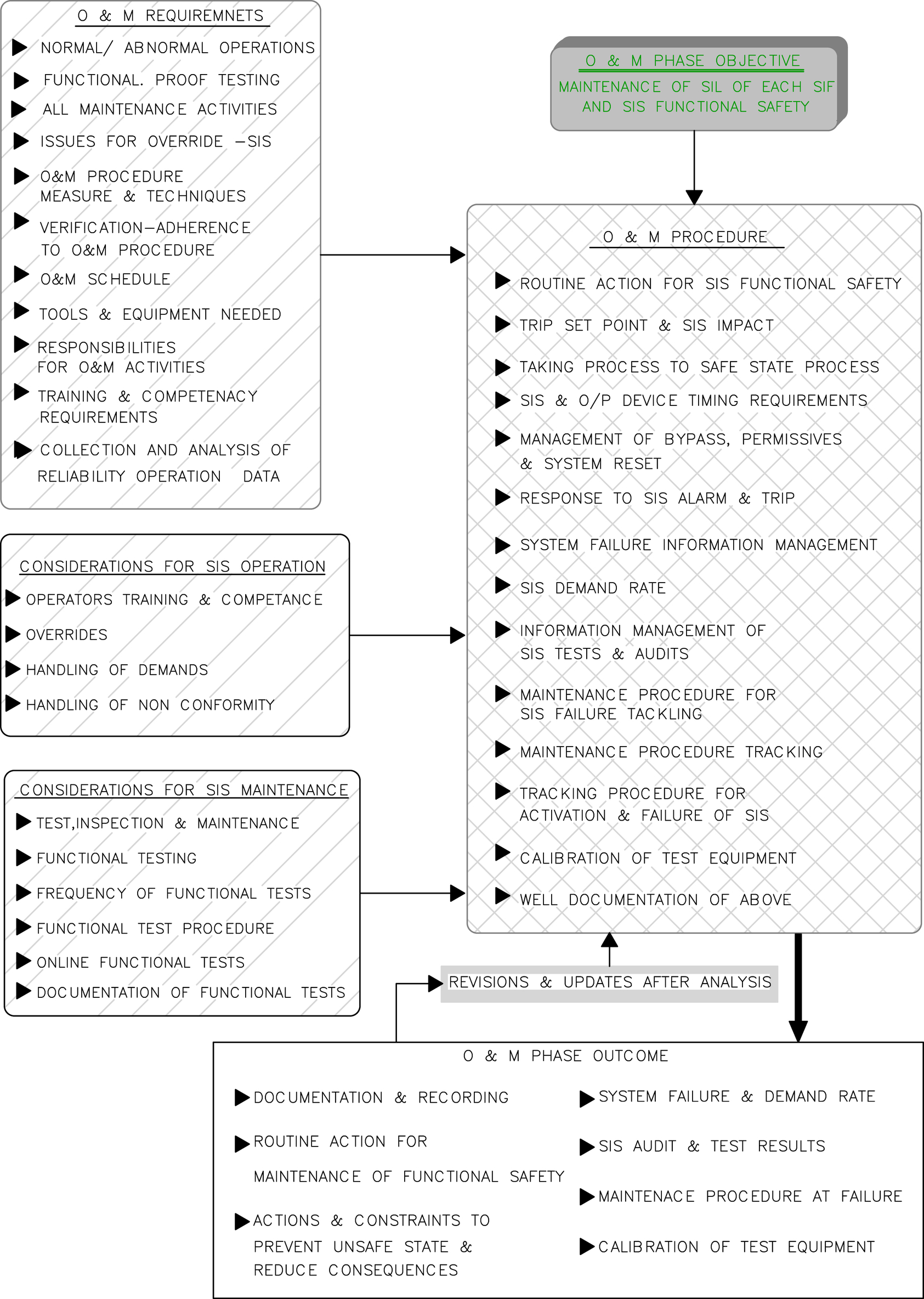
There are a number of requirements for the O&M phase. Also there shall be a number of considerations for operation of the system and considerations for maintenance of the system. All these requirements along with separate considerations for O&M are detailed in Fig. X/1.4.2-1. Since these are well depicted and self explanatory they are not explained again.
1.4.3. O&M Procedure
The O&M procedure with details depicted in Fig. X/1.4.2-1 needs to be developed. The procedure shall be developed taking into account various factors from requirements and considerations for O&M in light of the main objective. Major issues toward developments of procedure are elaborated in Fig. X/1.4.2-1. Documentation is an important part of the procedure. These documentations are subject to statistical analysis, which at a later date will provide the means for updating the procedure, as shown in Fig. X/1.4.2-1.
1.4.4. Outcome
Appropriate recording and documentation of the procedure is as follows and is briefly shown in Fig. X/1.4.2-1:
• Maintenance of functional safety in normal and abnormal conditions of operation of the facility
• Actions to be undertaken to prevent unsafe condition and how to reduce consequences of hazards
• Handling of system failure and demand rates
• SIS audits and test results
• Maintenance procedure during failure situations
• Proper calibration of test equipment
For details on the O&M phase technical requirements, considerations, etc., Fig. X/1.4.2-1 may be referred to. With this discussion on SIS implementation concluded (excluding reference to management of change), the next clause will focus on SIL certification and proof testing.
1.5. Modification and Management of Change
Management of change (MOC) is part of the operation section of the life cycle and the last phase in the active safety life cycle. At first modification is proposed (due to any requirement), then it is followed by MOC. A brief MOC process is elaborated in Fig. X/1.5-1. On account of (say) modification in legislature or development in a software program there is a need for change in SIS design. This phase deals with how to handle these changes. From Chapter VI it is clear that all such changes require detailed analysis as well as authorization of the entire process.
1.5.1. Objective
The basic objective of this phase mainly includes the following:

Figure X/1.5-1 Management of change (MOC) process. SIL, safety integrity level; SIS, safety instrumentation system; SRS, safety-related system.
• There must be an assurance that required safety integrity of the SIS is maintained even after the changes.
1.5.2. Requirements and Considerations
Based on the requirements for changes there are a few considerations for analysis, along with the main requirements of changes. Salient points are well elaborated in Fig. X/1.5-1 for MOC. The following issues need to be addressed prior to proposed MOC:
• Description of changes
• Reasons for changes
• Preliminary hazard identification
• Configuration history and audit trails
In addition, testing is necessary for proper implementation of changes and impact, etc. This is stated under MOC.
Overall, the MOC process is mainly concerned with:
• Changes
• Impact of changes
• Required testing
• Date
• Author
• Approving authority
These are detailed in Fig. X/1.5-1, which is self-explanatory.
With this implementation (actual application of Phases 3–7), the active part of the safety life cycle is concluded. Now, the focus will be on the other aspect of implementation of various requirements pertinent to the safety life cycle. In the following clause, concentration will be given to issues related to certification and proof testing.
..................Content has been hidden....................
You can't read the all page of ebook, please click here login for view all page.