
Chapter IV
Guided Word Hazard Analysis
Abstract
Hazard and operability (HAZOP) and failure mode and effect analysis (FMEA) are very popular in guided word hazard analysis. Both systems require cross-member team formation and technical information to carry out fruitful analysis of the system defined within a system boundary. HAZOP is very much suitable for continuous and batch process hazard analysis through brainstorming with the help of guided words in conjunction with various parameters of the process. Control hazard and operability (CHAZOP) adapted for electrical/electronics/programmable electronics is somewhat different from normal HAZOP and this has been dealt with separately. There have been attempts to automate HAZOP, which need special attention, and have been discussed. For identification of early design faults in products, and faults in the production process, FMEA is well suited. FMEA is also applied to software products and automation systems. On account of the systematic failure of software, separate treatments are necessary for software FMEA. For FMEA automation, various modeling methods, using Little-JIL process language and fuzzy approaches, are some of the new concepts covered here.
Keywords
Automated FMEA; Automated HAZOP; CHAZOP guidewords; Continuous and batch HAZOP process; Criticality analysis; Digraph; Fuzzy approach; Petri net; Risk priority number (RPN); Software FMEA (SWFMEA)
Guided word hazard techniques are basically a qualitative approach but more systematic. In this method, potential design and operating hazards are identified through questions and answers with the help of a few guided words to discover what would happen if a procedure is skipped/reversed or performed incorrectly. The guided words provoke thoughts in a brainstorming session to find deviations from design intent or set operating procedure. All such deviations could lead to a potential hazard. Therefore, with the help of these guided words, hazards are identified. In this method, an experienced team leader guides the team through the entire design document or operating system of the selected part of the system falling within the boundary of the defined scope. An experienced team leader guides the team with the help of a set of words popularly known as guided words, which are applied at specified points or study nodes and are combined with system parameters (process parameters) to identify the deviation with respect to the design intent or operating procedure. After the potential hazardous situations are identified, their causes and consequences are also analyzed. A control measure or action to prevent or mitigate the hazard is prescribed. In guided word techniques, report preparation is also extremely important. Since the guided word technique involves brainstorming and is systematic, it is necessary that there shall be some background work prior to carrying out the main job. One of the basic functions is to form a team and team leader and work out suitable planning. Two types of guided word techniques will be discussed in this chapter. These are the hazard and operability (HAZOP) study and the failure mode and effect analysis (FMEA) study. In each of these cases, basic system study, system study for electrical/electronics/programmable electronics (E/E/PEs), and automation of HAZOP and FMEA will be covered.
1.0. HAZOP Study/Analysis
1.1. HAZOP Study Feature
Dr. H.G. Lawley is very much associated with HAZOP for his contribution. HAZOP study was developed by ICI in the 1960s. Later the Chemical Industries Association supported HAZOP and produced a number of guidelines in 1977.
1.1.1. HAZOP Definitions
What is HAZOP? A HAZOP study is a structured and systematic investigation of a planned or existing plant or operation to identify and evaluate hazards that may represent risks to personnel, property, environment, or prevent efficient operation. This is a guide words-based qualitative technique carried out by a multidisciplinary team (HAZOP team) during a set of meetings. It is a versatile study technique and can be applied to a wide range of applications, both continuous systems as well as batch processes. The applicable international standard is: IEC 61882. “Hazard and operability studies (HAZOP studies)—Application guide.” The basic scope of the standard is: “This International Standard provides a guide for HAZOP studies of systems utilizing the specific set of guide words defined in this document. It also gives guidance on application of the technique and on the HAZOP study procedure, including definition, preparation, examination sessions and resulting documentation and follow-up.”
1.1.2. HAZOP Outline and Characteristics
The various characteristic are as follows:
• HAZOP study is a structured, systematic, and rigorous analysis of a system design and operation, by a team of experts. In this hazard analysis, system design and operations are studied stage by stage or line by line in a brainstorming, open, and creative way. A meaningful deviation is discovered by carrying out the study with the help of a set of guide words in combination with the system parameters. Here, “meaningful” is very important because all guided words (discussed later) may not be applicable to all the parameters, for example, guide word “NO” could be used for flow through a pump, but “NO” is not applicable to temperature as temperature is not physically possible!
• The team mainly concentrates on those deviations that could lead to potential hazards. Deviations are evaluated by the team, utilizing experience and judgment to pinpoint the consequences (may be risk ranked) and recommend actions for safeguards if current control measures are found inadequate or calls are made for further investigation of the problem.
• An experienced team leader develops a model for the system design or operation with pertinent information such as main design and operating procedure with details about materials, material safety data sheet (MSDS), main equipment used in process flow, and historical data about the plant hazards. The team creates the deviations for which it suggests causes, the consequences are estimated using the team's experience, and existing safeguards are taken into account. A formal record is generated.
• HAZOP is capable of identifying potential hazards and operational problems in terms of plant design, operation method/strategy, and human error. Therefore, by applying HAZOP during the detailed design stage, with special emphasis on operation and functional controls, money and time can be saved, especially during the operation stage, from add-on controls at a later date (resulting from an accident!), and there will be fewer problems in commissioning and in operations.
• In HAZOP, the entire process/design and operation is questioned with the help of guided words applied to various parameters to find the deviation. Guided words are so chosen that they focus on testing the system integrity and try to find any conceivable hazard. It generally gives total coverage for identification of potential hazards for the entire system, and necessary control measures can be applied to prevent accidents. However, sometimes it may happen that the immediate solution to a problem may not be obvious and might need further consideration (maybe by a specialist). It is more suitable for process plants but could be used for other applications including E/E/PEs.
• Choice of the right team with a team leader, details of information available, and quality of design finally determine the quality of the study report and performance of the study.
• It is a well-recommended practice by professional bodies and legislatures.
• On account of the nature of brainstorming, the study process offers a creative concept to find new deviation causes and consequences, which can be helpful in suggesting better control measures. It can be used in various plant stages/modes (only accurate sufficient information is necessary). It finds its applications for:
• Plant design study
• Normal plant operation
• Reduced output operation
• Normal startup
• Normal shutdown operation
• Emergency shutdown operation
• Plant construction/commissioning
• Special operating mode
• At present, HAZOP is extensively used by the majority of companies, especially those where engineering practice involves elevated operating parameters:
• Oil and gas production
• Flammable and toxic chemicals
• Pharmaceuticals, etc. to name a few
1.1.3. Objective, Scope & Boundary and Study Stages
At the outset, discussions on the study process were presented, so that the reader can develop the concept of objective and purpose. It is needless to state that for effective analysis, scope and boundary must be defined properly.
• The basic purpose and objectives of hazards could be as follows:
• HAZOP is used to identify the design, operating, and quality problems related to planned process. Operational problems generally come from human error, operating procedural error, or from equipment/control system reliability issues. HAZOP is well suited for such applications.
• It tries to find the relationship between various codes and standards with the process to check and see that no hazards remain undetected.
• It focuses on testing the system integrity and tries to find any conceivable hazards at the design stage, normal operating mode, startup/shutdown mode, etc. It is a hazard identification technique and not a problem-solving issue (control measures are developed later through discussion—not truly a part of the technique).
• Scope and Boundary: As is clear from these discussions, the study covers the entire spectrum of the process. Therefore it is imperative to state that scope definition and boundary selection are an absolute necessity, otherwise they may be uncontrolled and will not result in a quality study. This scope covers initiation of the study, recommendation of control measure, follow-up, and implementation, that is, at various stages of the study. So, at every stage, experience and judgment of team members are essential. For large plants, this is done by dividing the entire plant into smaller independent sections and carrying out the study of each of these sections separately. This will also offer a benefit of taking the help of specialists, for example, a process engineer in a water treatment plant can better contribute to that plant. Similarly, a mechanical engineer in a coal handling plant can offer better expertise on that plant. So, it is better to divide the entire fossil fuel power plant into smaller sections as indicated. Potential hazards related to health, safety, and environmental (HSE) issues are normally addressed in HAZOP but in addition to these, the issues related to reliability of equipment/control systems, product quality, operating procedural issues, maintenance, and other related issues are often covered in the scope of this study. Also plant downtime, etc. could be calculated. The study covers normal operations and startup and shutdown conditions as well. So, proper definition of scope in all these aspects is important. It is essential that the boundary of the study must be well defined at the beginning of the study so as to achieve a better result. Boundary definition indicates which physical section(s) of the plant need to be included. Here, another important point is how will the interface be handled, that is, how will a problem outside the defined section be dealt with? In addition, if there is more than one study, then how will the interface be handled so that nothing is missed or there are no duplications? It is not easy to state here how the boundary could be defined (though some indication has been given in the example), as it is very much dependent on complexity of the plant, nature of the plant, type of process, inherent hazard interrelation among the units, standard or new or proprietary system is in the question. Also for sequential operations, manual/automatic control modes have bearing on taking decisions on boundary definition. The raw mill section and kiln section of a cement mill are apparently independent of each other with silos at interface points, so, in which section should the raw meal silo be considered? Similarly, in offshore plants, the mud section is not directly related to the drilling or pipe-handling sections, but for the drilling operation (choke and kill), mud is essential. So, the interface part should be given proper attention when defining the boundary. Sometimes “HAZOP by difference” may be effective in some cases. Suppose one utility authority has a number of subcritical power units whose HAZOP study results are available. When the authority implements a new supercritical power unit, it will be useful and time saving to carry out “HAZOP by difference,” that is, by comparing.
• Sequence of study and variations with stages: In Clause 1.1.1 the outline of HAZOP was discussed, and it is clear that the following are the basic steps:
• Intention
• Deviation
– Cause
– Consequence
• Safeguard
• Corrective action
Each of these steps with an explanation is highlighted in Table IV/1.1.3-1. HAZOP studies can be undertaken at various stages in the life cycle of the project and each time the purpose is different. Fig. IV/1.1.3-1 depicts HAZOP studies at various stages.
Table IV/1.1.3-1
| Step | Explanation |
| Intention | Process designer to highlight plans for one section/piping and instrumentation diagram (P&ID). General scope and intention discussed. Relevant part highlighted with dotted line. Process designer to explain the part and general discussion. |
| Deviation | Line-by-line study commences with team leader choosing relevant guide word. Deviations with potentiality for hazards are noted. Team leader goes through all relevant guide words one by one; when all guide words are exhausted the next line is chosen and this line is highlighted firm meaning that its work is done. When all lines in this way are complete, that is, all are highlighted firm, additional words may be chosen to check the entire P&ID. |
| Cause | Cause for each of the deviations is identified. |
| Consequence | For each of these deviations, consequence (combination of likelihood of occurrence and severity) is identified through creative and brainstorming discussions. Consequences that warrant action are recorded. |
| Safeguard | Existing safeguard is evaluated during meeting and new control measure if any is prescribed. |
| Corrective action | When warranted, detailed quantitative risk analysis (QRA) or reliability analysis may be undertaken for complex systems at a later time. |
| NOTE | The purpose of this study is to identify hazards that require solutions and NOT the solution proper. |

1.1.4. Team
In this clause participants in HAZOP are discussed. The responsibility, qualification, and experience of each of the team members are discussed here. However, this is a general guideline; based on company policy and plant requirements the team formation may vary. In this connection generalized citation in Fig. IV/1.1.4-1 may be referred to.
Out of all the team members, the team leader and scribe (secretary) are required to possess experience in HAZOP and excellent communication skills. Generally, for plant HAZOP analysis the team is formed from people with a technical background. In most of the plants dealing with hazardous materials, and/or any other hazardous situation, a person from the HSE department is made a team member. In some countries it is mandatory to keep one person from HSE. Since in most plants, control instrumentation plays a great role in ensuring plant safety through interlock and protection, it is better to keep one person from process, operation/production engineering, and control and instrumentation engineering. Guidelines about the qualification and responsibility of team members are given in Table IV/1.1.4-1.

1.1.5. Information Required
To take up or start HAZOP studies, information about the plant is necessary and this is detailed in the following:
• Continuous process: The following background information is helpful for the study:
• Process and instrumentation diagram
• Design specification
• Other details such as process flow diagram, mass and energy balance
• Chemical reaction details
• Operating/control philosophy
• Equipment/instrument specification
• Site data and plant layout
• Alarm/trip/relief valve set values
Table IV/1.1.4-1
Team Member Qualifications and Responsibilities
| Member | Qualification and Experience | Responsibilities |
| Team leader | Meticulous and analytical skill Trained and experienced in all stages of HAZOP (acting as scribe) Quick adaptation and technical understanding capability Very good communication skills and temperament to work in a team Guidance and motivating skill, technical competence including knowledge on QRA | Developing a conceptual model, planning scheduling Proper division of the process so there will be quality production of the study report and at the same time it is not too time consuming and costly Controlling discussions at all stages with open heart Keeping focus, motivating, and helping scribe to record Judgmental power and leading the team from the front To ensure completeness (within the defined scope and boundary) and quality of the study report |
| Scribe | Familiarity with HAZOP Full-time job and able to start recording without depending on detection when consensus is reached To have good working relationship with team leader as helper | Taking notes of all events, recordings and documentation Establish good relations with team leader and get more time when required Production of interim report and list of recommendations Inform all details about recording Check progress and produce final report |
| Members | Good exposure and knowledge about HAZOP and sufficient experience in the area of his/her service Comprehensive knowledge on intent of design and/or operation Good knowledge on discipline represented | Process: Outline description of the process and intent of design/operation. Process parameters with associated design conditions Operation/control and instrumentation engineer: Depending on applicability, operation procedure, plant stability, control philosophy, details of interlock and protection, alarm lists, and other safety startup and shutdown features and requirements Design engineer: Specification details, material safety data sheet (MSDS), piping and instrumentation diagram (P&ID), layout information Maintenance engineer: Maintenance update, management of change (MOC) |
• Hazard area classification
• Known operating problem
• Hazard history
• Startup/shutdown problems
• Batch process: In addition to this information, the following information is also necessary for batch process, especially when automation is associated:
• Detailed operational method
• Step-by-step operating procedure
• Outline of control sequence especially for automated job
• Time-dependent sequential operation
• Reaction process heat and flow details
• Physical and chemical properties of reactants
• Design intent of each stage
1.1.6. Preparation and Planning
With the background information sought in the previous clause, there will now be a stage for preparing and planning before actual HAZOP can be undertaken. Some of these points are related to standard norms for HAZOP and some are for planning of HAZOP:
• The team shall be well informed about the intent of the study and a conceptual model shall be presented to them at the start of the meeting.
• As HAZOP study changes with the stage of the project as shown in Fig. IV/1.1.3-1, during planning this needs to be taken into consideration.
• The team leader may meet with the process engineer in advance of the study so that he/she has a good grasp of what the process is all about, and to agree a mutually acceptable basis for dividing up the P&ID into short sections suitable for individual study.
• A fresh copy of the P&ID will be put on the table at the HAZOP study as a clean drawing, and any markings made on it will be done in the presence of the HAZOP team. This second copy is then called the “HAZOP master.” As discussed in Clause 1.1.3, for a HAZOP study each P&ID is divided into sections. No section should feature a process line junction (as interfacing is very difficult) and no step should cover more than one element. In a continuous process, these divisions can be done based on variation of process variables, on the basis of a junction in vessels i.e., terminal point at vessel, or at a predesired control point.
• Information on P&IDs is very important, so important information expected from one P&ID is listed here:
• P&ID to show all piping including physical sequence and branches with valves, equipment, and instruments with final destination with associated tag numbers.
• Miscellaneous drain and vent lines, relief valves, etc.
• Flow directions, permanent startup/blowdown lines
• Necessary interface points
• Another important point to be noted is that a system becomes more vulnerable during startup/shutdown, etc., so in the study special attention may be given to these phases also.
• A special feature in a batch process is that a single piece of physical equipment may be studied several times in HAZOP, for example, a reaction vessel, but in different perspectives, so due consideration shall be given in each situation.
• The team needs to look at the whole process and the changing conditions at each stage of the batch process. These are more important because they are all time dependent sequence, time related flow and process. A deep understanding of design intention at each stage is crucial. Without a proper understanding, a vital step or stage may be missed.
• For better results, the more divisions of the process there are, the better the quality will be. However, this may demand more time and money. The team leader needs to pay attention to this too (see the responsibility of the team leader in Table IV/1.1.3-1).
• Complexity and size of the plant within the scope and boundary of the study determine the time and cost requirement. It is the responsibility of the team leader to guide the team in such a way that the study is properly balanced. Previous HAZOP study results of similar plants could be helpful.
• A stretch of no more than 4 h in a day and no more than 4 consecutive days in a week should be deployed for one study. There shall be a number of breaks in each session so that team members can produce better results. However, there shall be no interruptions in the session. Typical timings for a HAZOP study are detailed in Table IV/1.1.6-1.
Table IV/1.1.6-1
Typical Timings for a HAZOP Study
| Type of Study | Preparation | Evaluation | Documentation |
| Simple and small plant | 8–16 working hours | 1–5 working days | 2–6 working days |
| Complex large section/plant | 2–6 working days | 1–5 working weeks | 2–5 working weeks |

• Meetings shall be well planned and scheduled by the team leader in advance, and a comfortable conference room shall be booked in advanced. In some sessions, help from other experts may be sought.
• Some formal training on study philosophy, principles, and methodology for team members is welcome before starting a HAZOP study. There are regular courses offered by various organizations for this. Otherwise for large companies where regular HAZOP studies are carried out, new people may be included with experienced personnel to receive hands-on training. Scribes need additional training to understand category and level of recording. They need to have good computer training in cases where computers are used for recording purposes. The requirements of training and experience of the team leader have already been discussed.
1.1.7. Effectiveness
There are several influencing factors for a HAZOP study to make it effective. The majority of these influencing factors are as follows:
• One of the major issues is availability of required accurate information. If the study is to be carried out for design stage hazards or operational hazards, then accurate data shall be made available. A HAZOP study based on precooked design or on outdated data is meaningless and futile.
• For the selection of an appropriate team leader a great deal of mentoring may be necessary, so that the concerned person can perform efficiently. Without a suitable team leader, the study will be ineffective.
• The selection of the team shall be a balance of experience and knowledge. Team members must be from different disciplines with good insight and skills.
• How the team is able to meticulously and systematically utilize the information for identification of deviation has an impact on the study. Therefore avoidance of hazards is directly related to effectiveness of the study. The ability of the team for creative thinking and systematic analysis influences the quality of the report.
• Maintaining a sense of proportion in the judgment of seriousness of hazard and expenditure toward reducing likelihood are influencing factors for the quality of the report.
• Only an authoritative person (with good knowledge) should initiate a HAZOP study, so that recommended actions can be properly implemented (see last part of Fig. IV/1.2-1).
• Administrative and financial support is essential.
• Proper planning and scheduling is also an important factor to achieve better results.
1.1.8. Pros and Cons of HAZOP Study
The following points may be noted as advantages and disadvantages of the study:
• Advantages:
• Helpful for hazards difficult to quantify, for example, human error
• Brainstorming and creative
• Systematic and comprehensive with the possibility of getting quality results
• Possibility of quantification
• Simpler qualitative analysis but quite accurate especially for process plants
• Possibility of automation
• Disadvantages:
• Requirement for a lot of information is ineffective at early stages
• Qualitative analysis, so in many cases further quantification is necessary
• Time-consuming and costly
• Highly dependent on scope definition, team performance, and accurate information for comprehensiveness and quality of result
• Inability to assess hazards caused by interaction between different parts of the system
1.1.9. Guided Word
Guided word is very meaningful in HAZOP. Guided words with meanings and comments are listed in Table IV/1.1.9-1.
• A few additional terms used for HAZOP analysis are found in Table IV/1.1.9-2.
• Some special words [1] may be:
• Testing: Product/equipment
• Plant equipment: Operable/maintainable
• Instrument: Sufficient/excess/location
• Electrical: Area/isolation/earthing
• Possible parameters with which guided words could be associated:
• Flow
• Pressure
• Temperature
Table IV/1.1.9-1
Generally Used Guided Words With Meanings
| Guided Word | General Meaning | Remarks |
| No (not/none) | Negation (of intent) | No forward flow |
| More (higher) | Quantitative increase | More of any physical parameter |
| Less (lower) | Quantitative decrease | Less of any physical parameter |
| As well as (more than) | Quantitative increase additional activity | Design/operating intent achieved along with additional item |
| Part of | Quantitative decrease | Only part of intent achieved |
| Reverse | Opposite of intention | Reverse reaction/flow |
| Other than | Complete substitution/miscellaneous | Original intention not achieved, something different happened—alternative mode of operation |
Table IV/1.1.9-2
Additional Guided Words With Meanings
| Guided Word | Meaning | Application |
| Early | Relative to clock time | Timing before intention |
| Late | Relative to clock time | Timing after intention |
| Before | Sequence order | The step (before) is effected out of sequence |
| After | Sequence order | The step (after) is effected out of sequence |
| Faster | Different (earlier) from timing intention | Faster reaction |
| Slower | Different (later) from timing intention | Slower reaction |
| Where else | Other location | Flow/transfer/source/destination |
• Viscosity
• Mixing
• Stirring
• Transfer
• Reaction
• Composition
• Addition
• Separation
• Time
• Separation
• Speed
• Phase
• Particle size
• Measure
• Control
• pH
• Sequence
• Start
• Stop
• Signal
• Operate
• Maintain
• Communication
• Service
Meaningful combinations of these parameters with guided words are presented in Table IV/1.1.9-3.
Out of sequence and missing are additional guide words found in batch processing.
This checklist of guided words will be helpful in HAZOP analysis. In most cases, parameters and associated guided words are quite obvious! With these general ideas and HAZOP study philosophy in mind, it is better to concentrate on the actual procedure.
1.2. HAZOP Methodology Description
HAZOP study methodology is discussed in this clause with Fig. IV/1.2-1.
1.2.1. Intent of the Study and Study Process
It is necessary that the team begins the study with full intention in mind. The team must know and understand the exact scope and boundary of the study and the stage of the project for which the study is intended. With available information or having a good knowledge of the system in question, it will be possible to develop a conceptual model of the system for which the study is intended. As discussed earlier, the team leader actually leads and imparts the detailed idea to the team members through a conceptual model and clears up any doubts about the entire system. Then a full description can be presented by the process person with all key parameters and HAZOP study intention formulated and recorded. To get a quality study it is better to have a detailed and comprehensive study intention. The intention of the study may be focused on equipment, material, conditions, controls, changes, etc. All these shall be spelt out in detail. During a detailed description, the scope and boundary definition along with interface points, which are extremely important, must be elaborated clearly, so that nothing is missed and unnecessary wastage of time is avoided.
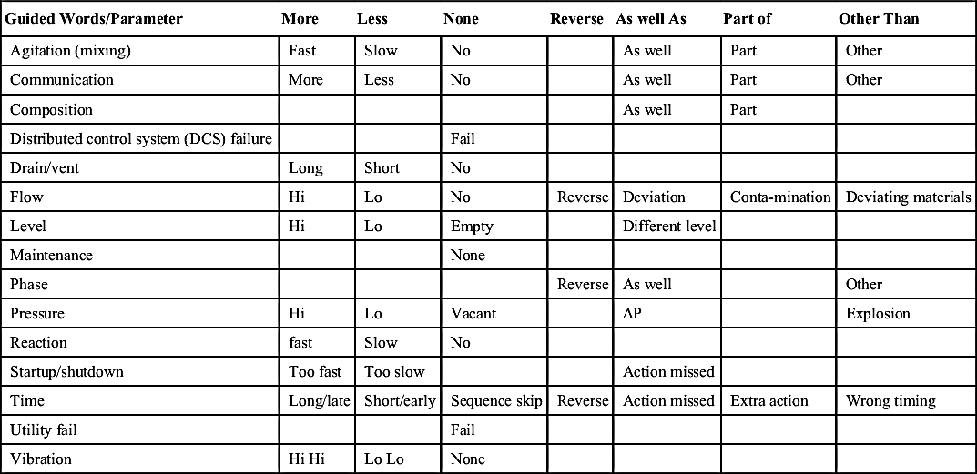
Table IV/1.1.9-3
Meaningful Combination of Parameters and Guided Words
| Guided Words/Parameter | More | Less | None | Reverse | As well As | Part of | Other Than |
| Agitation (mixing) | Fast | Slow | No | As well | Part | Other | |
| Communication | More | Less | No | As well | Part | Other | |
| Composition | As well | Part | |||||
| Distributed control system (DCS) failure | Fail | ||||||
| Drain/vent | Long | Short | No | ||||
| Flow | Hi | Lo | No | Reverse | Deviation | Conta-mination | Deviating materials |
| Level | Hi | Lo | Empty | Different level | |||
| Maintenance | None | ||||||
| Phase | Reverse | As well | Other | ||||
| Pressure | Hi | Lo | Vacant | ΔP | Explosion | ||
| Reaction | fast | Slow | No | ||||
| Startup/shutdown | Too fast | Too slow | Action missed | ||||
| Time | Long/late | Short/early | Sequence skip | Reverse | Action missed | Extra action | Wrong timing |
| Utility fail | Fail | ||||||
| Vibration | Hi Hi | Lo Lo | None |

1.2.2. HAZOP Methodology and Risk Assessment
There are several steps in HAZOP methodology and risk assessment, which starts with finding deviations to identify hazards.
• Deviation and hazard identification: The team leader is responsible for starting and terminating the meeting on time, as discussed earlier. The team leader begins by calling on the process engineer to give the overall process description and the design intent for each P&ID. The team leader then defines the first section to be studied in detail and may put a dotted yellow line on the HAZOP Master to ensure that everyone is looking at the same section of the plant. The team leader then calls on the process engineer to give the design intent and detailed information about the contents of the line, the design and operating temperature and pressure, etc. For each of the sections, deviations are discovered. For hazard identification, it is better to refer to the third box “Analysis Details” in Fig. IV/1.2-1. The team leader writes onto the HAZOP Master the number of the action in red, next to the item to be changed. If the change is agreed by the meeting, he/she also marks up the HAZOP Master in red with the change to be made. When all the guide words have been used and the study of a subsection is complete, the team leader should color yellow all the completed sections. The team leader then defines the second section to be studied in detail and calls on the process engineer to give a detailed process description. The extent to which the hazards will be evaluated, ranked, and solved varies with company policy, objective, etc. defined at the planning stage.
• Combination: In the drawing a guided word is selected and combined with a parameter of the element/line. This means that a meaningful deviation is to be created with the help of the combination of a guide word and one parameter. Naturally, these combinations can be done either by selecting a parameter first, then combining one guide word as shown in Fig. IV/1.2.2-2A, or a guide word may be chosen first and combined with a parameter as shown in Fig. IV/1.2.2-2B. For a complete flow diagram of HAZOP methodology Fig. IV/1.2.2-2 should be viewed in conjunction with Fig. IV/1.2.2-1.
Thus from the discussions, it is clear that guide words and parameters are combined to get a meaningful deviation. Here, the word “meaningful” is very important in the sense that if the combination of guide word and parameter gives a deviation that is unrealistic or incredible, then it shall be discarded, for example, “NO” with “TEMPERATURE.” It is important to select a set so that none will be missed. For this, various standard combinations discussed earlier or additional alternative combinations may be tried. HAZOP is a creative process, so new combinations to find meaningful deviations are necessary for the process.


Figure IV/1.2.2-2 HAZOP methodology alternative approaches. (A) Parameter selection first, (B) guide word selection first.
• After a credible/meaningful deviation is identified, then it will be necessary to find the causes.
• For any cause that is not like what has been discussed previously, there shall be a brainstorming session to find all probable causes. There shall be a positive attitude from all the members even if for some reason a team member may be responsible, for example, if the cause is “lack of maintenance,” then the member from the maintenance group needs to have a positive attitude.
• Human error, equipment/control system failure, or procedural mistakes should be dealt with properly.
• Available data bank/old history standards, etc. will be helpful. However, since HAZOP is a creative process, a data bank/old history should not hinder the brainstorming session/creativity. Data from these sources are helpful to ensure no cause is overlooked.
• After hazard identification, risk assessment is performed. Acceptable risks are arrived at by balancing frequency of occurrence and severity, as discussed in Chapter II. It is quite possible that such assessment is done outside these meetings. Here, a realistic hazard is important and it is very much related to frequency. So, the term realistic hazard varies greatly with industry, company/company policy (to an extent), legislature, and country. In any case, the cause needs to be recorded even if it is very low frequency. All major causes and consequence are noted. In a HAZOP study the cause and consequence discussions are very closely coupled. For better results, these may have to be covered, in conjunction with safeguards, in a separate meeting—after the main study of all the lines is over.
• In a HAZOP study, after all causes of the deviations pertinent to a parameter/guide word are covered, another parameter and guide word combination is sought. If a parameter (/guide word) is chosen first, then the next guide word (/parameter) is combined with it to obtain a meaningful deviation. If all such combinations are complete, then next parameter (/guide word) is chosen and the process continues until all parameters (/guide words) are complete, as shown in Figs. IV/1.2.2-1 and IV/1.2.2-2.
• As shown in Figs. IV/1.2.2-1 or IV/1.2.2-2 the next line/subsection is chosen and the process is continued in this way until the study of all lines and/or subsections is complete (i.e., the entire procedure is repeated for each element in the part/subsection and for all subsystems within the scope and boundary of the study).
• The need to receive and incorporate action responses may be decided in a special coordination meeting.
1.2.3. Consequence Analysis
As discussed earlier, cause and consequence are closely coupled. However, in some approaches safeguards are not considered initially and only consequences are considered pertinent to all causes. Finally, safeguards are applied to obtain the final recommended action. Normally, it is the prerogative of team leaders to decide when to carry out the consequence analysis. In most cases it is seen that such exercises are done after each subsystem study is complete, so that all causes and consequences can be carefully studied. It is necessary to see if the system goes beyond the intended operating range or into the danger zone. The consequence may be immediate or long term; it may be within the plant and outside the plant (especially environmental impacts). Another important part is the development of consequences and how operating personnel are informed of these through use of a pretrip alarm, interlock, and trip sequence. A sequence of event recording is done to check the system. This will be helpful in detecting human error. In consequence analysis, various safeguards play a major role and shall be seen together.
1.2.4. Safeguards and Recommended Actions
There are several ways to look into the problem:
• To ignore the existing system, identify the cause and consequence of the hazard, and then apply the safeguard such as an alarm, interlock trip, etc. In this method there is very little chance that anything is missed.
• To consider all safeguards and based on the situation come up with an additional recommended action.
• In any case, risk is assessed qualitatively by utilizing the experience and judgment of the team using risk matrices, as discussed earlier. However, if there is a necessity to assess a risk whose frequency is very low but severity may be high, this will be recommended for further analysis by QRA.
• All recordings, namely, causes, consequences, and recommended actions, must be recorded clearly and unambiguously, so that at a later date a third party may understand. Assumptions if any must be recorded also. When a safeguard is adequate, causes and consequences are recorded. If a safeguard is inadequate, then additional recommendations may be needed. There are various ways these recommendations are given in and outside the meeting, as shown in Fig. IV/1.2.4-1.
• As seen in the drawing, in some cases the recommended actions are left for decision by a respective field expert. In some cases where the recommended actions are warranted by a standard and/or when there is consensus, then actions are taken in the meeting balanced are left for outside meeting decision. In some cases a team leader may be confident that all decisions may be taken in the meeting. Specific recommended actions are always preferable; however, for certain cases where there are repetitions, generic recommended actions may be called for.
1.2.5. Influencing Factors During HAZOP Study
There a number of factors that affect the study intensely. Some of these points were discussed earlier. In Table IV/1.2.5-1 these are put forward in a consolidated manner.
1.2.6. Generic Example
As discussed earlier, it is difficult to consider a section of a plant within the scope of this book. For this reason a simple generic example has been chosen. A shell and tube-type heat exchanger is used in most plants. In the heat exchanging process, as shown in Fig. IV/1.2.6-1, fluid passes through the tube and cooling water passes through the shell to cool the process fluid to the desired temperature with suitable control (not shown). Here, a few points should be noted. In the particular example, only the HAZOP worksheet has been shown for cooling water. In this case, three of the most relevant guide words—“None,” “More,” “Less”—have been associated with parameter flow. Here, flow parameter is chosen first, then the relevant guide word has been associated with it to obtain the deviation.

So, with a little background about the HAZOP worksheet it is better to concentrate on how HAZOP reports are produced and presented.
1.3. Reporting and Follow-Up
Like all other hazard analysis methods, reporting in HAZOP is also very important; it shows the actual work carried out by the team. The purpose of HAZOP documentation is to record and represent the discussions by the team during the study meeting. One thing that must be kept in mind is that the report shall be very clearly and systematically recorded so that it can be used by others in the future. Major content must include what, why, how, when, and by whom. Regarding reporting format, it is important to note that the report may be used for a number issues, such as:
Table IV/1.2.5-1
Influencing Factors During HAZOP Study
| Factor | Discussions |
| Motivation | Experienced team leader must be able to motivate to extract the best out of the team members for a quality result. Also high-quality communication and positive openness of team members are critical. |
| Time | Time affects the system in two ways: sufficient time shall be allowed to perform the work. Also since this is a creative exercise it should not be continued for a long period. The study should always be carried out with fresh minds. Also team members should be expected to work out of hours to achieve results. |
| Scope and boundary definition | For a new project or for a modification work, scope and boundary definitions are extremely important, especially for a connected system. There shall be a clear description of the system, intent of study, and study envelope. This is because any modification in one subsystem may affect other subsystem, for example, a modification in a feed water system may directly affect a condensate system. The same applies if this is modification work, for example, if a superheater temperature control is modified, then one has to keep in mind that it may not only affect reheat temperature control but also heat distribution in a once-through supercritical boiler. |
| Action | Details regarding recommended action were discussed in the previous clause. It is recommended that all actions during the study should have consensus. The team leader needs to decide what actions will be taken within the study limit and how much shall be allocated to outside experts. Also whatever action is recommended it must be relevant and unambiguously defined, so that at a later date a third party may understand. Also while recommending any action, all aspects like hardware/software failure/procedural mistake, and/or human error need to be considered. |
• Action implementation
• Link for future HAZOP
• Contractual document to meet standards
• Safety database for the plant
• Future training
• Troubleshooting
Therefore recording and report preparation can never be overestimated. It is worth noting that all the background information based on which study has been carried out should be part of the dossier. This will be helpful for further reference as well as to mark the changes in the future. Therefore the amount of information in the HAZOP final report will vary from case to case. Each section shall be covered fully with a selection of guided words and a heading.

1.3.1. Recording Format
Discussions are normally recorded in tabular format, as shown in the generic example in Fig. IV/1.2.6-1. There may be variations in recording format based on the scope; however, the following information is generally included:
• Reference number
• Guide word
• Parameter
• Causes
• Consequences
• Safeguard
• Action required
• Action allocated
The column headings in bold are essential. However, in some cases, either a guide word or parameter is put as a subheading just above the table, as shown in Fig. IV/1.3.1-1A and B. It is always better to include the safeguard column in tabular format. Also all entries should be numbered for proper understanding as well as referencing. To facilitate risk matrix formation for risk ranking, frequency of occurrence, severity, etc., other columns may be added.

Figure IV/1.3.1-1 Typical recording format for HAZOP Study. (A) Recording format of HAZOP with guide word. (B) Recording format of HAZOP with parameter.
Recording formats shown in the figure will form the part of the report after these are finalized. Before finalizing, draft recordings should not be made a part of the dossier. Follow-up is another important aspect of the HAZOP study. Typical formal HAZOP follow-up action close-out is presented in Fig. IV/1.3.1-2.

1.3.2. Detailing in Record
The amount of detailing to be included in the record is highly dependent on purpose. Several modes of HAZOP tables are:
• Deviation by deviation HAZOP table
• Cause by cause HAZOP table
• Exception only HAZOP table
• Action only HAZOP table
Another way HAZOP tables (generally in use) can be categorized is as follows:
• Full record: A full record system is very useful for subsequent usage. Generally, full records are done to keep parity with company norms or when it is required to meet the requirements of legislature. In fact, from an auditing perspective it is necessary to ensure that HAZOP is documented as fully as possible. Each deviation created by combining a guide word with the parameter provided gives meaningful deviation. In full recording, any deviation observed by the team is recorded, even if it is insignificant. Also all guide words are listed, even if not used for deviation finding. In detailed recording, safeguards are more likely to be maintained, as the function and purpose are recorded in detail in the HAZOP. Naturally, this type is time-consuming and costly.
• Record by exception: This is the other extreme of recording. Here, these will be listed only when the team recommends an action. These are done very quickly but have little value for general or subsequent use because they are the result of immediate and shorter meetings. However, reporting is simpler and less costly. Usually, this type of report is done for short study completion time.
• Intermediate: In this there will be sufficient discussions within the team and incidents are noted even if no action is recommended. If there is any action it is noted, but here deviations are also noted that are realistic but well guarded by the safeguard system in service (no action). This can be used at a later stage for general and audit purposes.
• One thing that should be borne in mind is that all the entries shall be very clear and unambiguous, so that there is no difficulty with future interpretations. Short or brief entries may lead to ambiguity at a later date.
1.3.3. Computerized Recording
The use of computers for HAZOP is quite common. In addition to automated HAZOP (discussed later), computerized recording is also available. The recording programs are basically special spreadsheets. This transition has resulted in thorough and quick recording of HAZOP studies. There are a number of features of use of computers for recording:
• The computer can be connected to a projector, thus it is possible to display what is being recorded to all the team members.
• During discussions it is possible to alternate between design intention, boundary, interface issues, earlier study details, etc. Also a huge databank can be made available within a few keystrokes. These are extremely helpful for the members conducting the study. HAZOP software makes it possible to review every deviation and refer back to common scenarios, and where common scenarios are met use set pieces of text to save time.
• Recommendations are easily retrievable and can be converted to actual documents.
• The scribe should be familiarized with such computer programming.
• HAZOP Manager V 7.0 and HAZ1508 from Rowan House Limited in the UK are just two examples of HAZOP software. These programs provide a framework for the study and perform the recording functions.
1.3.4. Follow-Up Action
Generally, follow-up action is performed by authorized personnel from line management. However, the team leader of the HAZOP team at times is given responsibility to pursue line management personnel for action implementation. For keeping track of action follow-up, Fig. IV/1.3.1-2 may be followed.
If any action is rejected or could not be implemented, it must be suitably logged in the record and duly signed by a responsible person. There shall be a proper check for management of change (MOC) or a new system before this action is commissioned.
1.4. HAZOP Discussions
1.4.1. HAZOP Timing (When to conduct)
The objectives of the study and benefit from it determine the timing of a HAZOP study. When the process design is complete, a full study procedure may be applied. Operating procedures may be examined to ensure that all eventualities have been considered. Modifications generally benefit from a rigorous study. Often an apparently simple, uncomplicated modification can give rise to a greater problem than it was intended to solve. Existing plant and new equipment are other examples of topics that may benefit from the study. Therefore a project may be studied several times in its lifetime with different objective and purpose.
1.4.2. HAZOP in Different Applications
Here, HAZOP in different plant applications has been outlined. HAZOP applications in E/E/PEs are discussed separately later.
• Existing unit periodic study: Periodic HAZOP studies of existing plants are not uncommon; rather they are legally binding to ensure that the plant runs safely throughout its lifetime. This is important, specifically when there is a change in operation procedure, material feed, product type, and/or major changes in the system. In the following cases, to ensure safety, such periodic studies are often done:
• Major incidents
• Design deficiencies
• Inadequate previous HAZOP study
• Plant not running smoothly
HAZOP is time-consuming but can give a more comprehensive output. In any case, time period/completion time for such a periodic HAZOP study is specified. Also the next periodic study dates need to be finalized.
• Similar or repeat design: It is quite possible that different units are set up by a company with a similar (or even the same) design. One company may have two or three different types of (say) 500 MW plants at different locations, or in the same location one is a drum-type boiler and the other is a once-through boiler. In all such cases HAZOP by difference, that is, detailed comparison of the two systems may be helpful. However, the team must be well aware of variations between the two systems.
• MOC: Management of change is another area where HAZOP is done. If the modifications are done in the plant (operating procedure, materials, catalysts, sequence, software, etc.), then the safety of the plant because of such modifications is often checked with the help of HAZOP. In such cases the modifications are considered as a new design and a HAZOP study needs to be carried out. Here, one thing needs to be kept in the mind that if such changes are minor/small, then the study can be done easily, but if the modification is large, then extent of the HAZOP study may be greater. If the plant had a HAZOP study done earlier, then such information may be very useful. Another factor is the scope and boundary definition. In many cases, some modification may have made wide changes in the system. In these cases, it is possible to consider a HAZOP study up to a certain distance (extend) from the point of modification, but that must be agreed upon by all members of the team. Otherwise HAZOP for the entire affected area needs to be carried out—it depends on what has been changed (MOC in case I: from 3 × 50% boiler feed pump (BFP) to 2 × 100% will be different from MOC in case II: from 2 × 60% induced draft (ID) fans to 3 × 50% ID fans just if we look at the complications of electrical bus transfer first case complication is less than the second one).
• HAZOP study for procedure: This is normally a detailed method and should be properly defined. This study is usually carried out by a well-balanced team from different disciplines. The information required includes but is not limited to procedure definitions, up-to-date P&IDs, and other relevant drawings and documents. Also the aim of the study (depth of study and major area of interest such as HSE, accident, etc.) needs to be well defined before starting a step-by-step procedure. Each stage/step and action is examined with the guide word to identify meaningful deviation for analysis for hazard identification. In the case of a HAZOP study for procedure, human error is an important factor.
• Drain vent and interconnections: It is quite common that drain vent relief from different equipment is interconnected through common piping. Occasionally, proper interconnections are not shown distinctly in any single P&ID; instead they are spread over a number of P&IDs. Also it is likely that there may be mismatch in material (compatibility), pressure, and mode of operation. So HAZOP studies in these cases are complex. This is because one needs to see interface management between P&IDs, fluid mismatch, and simultaneous operation of two pieces of equipment. It is therefore necessary that there shall be one P&ID where all these, for example, material release, fluid incompatibility, pressure mismatch, simultaneous operation, etc., shall be clearly marked or in each P&ID fluid material, pressure, release mode, and interface point shall be well defined. For HAZOP, study parameters (with their guide words in parentheses) are shown: Pressure (More), Flow (No, Reverse, More), Phase (Change), Temperature (Low, High). The HAZOP study needs special attention for these cases and so are discussed separately.
• Major issues related to HAZOP in commissioning are dealt with in the main HAZOP study:
• Removal of construction debris
• Purging and cleaning
• Testing of major equipment
In a test run different fluids may be used, so during HAZOP connected with commissioning the following guide words may be useful: Density: Higher/Lower; Noise: Higher; Debris: More/Some; Contamination: Oxygen/Inert—Source and Disposal; Cleanliness: More/Less; Stress: More, etc.
1.5. Computer HAZOP
Conventional HAZOP are useful for process and equipment failure but are not really suitable for control systems utilizing computers. This is, not suitable for E/E/PEs deployed for plant control systems. In view of the current system architecture of control systems, it is better to refer to such control systems as E/E/PEs rather than computer control. Conventional HAZOP does not take into account the potential hazard caused by failure of system/system components, and does not consider control logic failure. It would be dangerous to go ahead with conventional HAZOP considering E/E/PEs as a black box, because many HAZOP findings are concerned with control and safety applications. Therefore by considering E/E/PEs as a black box many such safety critical potential hazards will be missed. E/E/PEs are much more flexible than conventional hardware control systems and many high-end sophisticated controls are possible by control systems based on E/E/PEs. E/E/PEs provide many benefits to the controls and at the same time introduce additional hazards also. In 1994 Nimmo developed a computer HAZOP (CHAZOP) system meant specifically for computers, that is, E/E/PEs. A framework similar to conventional HAZOP is used for CHAZOP with different interpretation and different guide words. In conventional HAZOP the guided word “NO” when associated with parameter “Flow” indicates no flow in the pipe. While in CHAZOP “NO” is associated with control signal/data flow to signify different meanings. There are two types of CHAZOP: Preliminary and Full CHAZOP. The obvious question is what, why and when should this CHAZOP be developed and implemented? The CHAZOP concept is shown in Fig. IV/1.5-1.

1.5.1. CHAZOP Conceptual Details (What, Why, and When)
Basically, HAZOP may be considered as an initial investment at the beginning to save money at a later date.
• What—the purpose: CHAZOP has a framework similar to HAZOP. There are several forms of CHAZOP for E/E/PEs but most of them are based on guided words driven by the HAZOP process. During earlier discussions it was seen that there are several protection layers for a process/plant. Out of these, CHAZOP is carried out on basic plant control systems (BPCSs). The CHAZOP method has been developed to generate confidence, that the instrumentation and control system has been designed, installed, operated, and maintained using good engineering practices and is capable of performing at the higher end of the allowable range of operation. Like HAZOP it is a team-based study and the review can be done at different stages of the project life cycle. At the early stage it is carried out to improve design; at the postdesign stage it is carried out for design verification. During the operational stage it is carried out to understand the impact of modifications/upgrades, etc. Therefore CHAZOP can be considered as a structured review process (based on HAZOP framework) intended to examine the potential threat to the claimed performance of the BPCS, with the help of an experienced team utilizing previous experiences. Thus CHAZOP encompasses general threats, hardware, software, and human factors, as shown in Fig. IV/1.5.1-1.

Various points considered in CHAZOP are different from HAZOP. These are:
• External factors: Temperature, humidity, ducting, smoke, etc. directly influence the performance of the control systems. Also if there is power, air, or hydraulic system failure, then control systems cannot work. Even if E/E/PEs are not secured or there is unauthorized access, then control systems will fail to work. All these are not covered in conventional HAZOP, but they are very much applicable to CHAZOP.
• Hardware failure: Detection of hardware failure/modes of failure of modules [e.g., input/output (I/O) module], etc. will have a direct impact on the performance of control systems. Naturally, in CHAZOP, such major failures, redundancy criteria, nature of fallback, etc. need to be considered.
• Software failure: There may be errors in the selection of objects, attributes in files, etc. and such software failure is extremely important in control systems and CHAZOP. This will be clear from a simple example: in HAZOP no flow means no flow in pipelines, but in the case of CHAZOP it may mean no data flow and this could lead to a catastrophe.
• Human factors: The display/log presentations have lot of bearing on operator action. Alarm presentation is extremely important so that many human errors can be avoided. Recommendations by the Engineering Equipment and Materials Users' Associations (EEMUAs) are very useful here. A typical recommendation of EEMUA in connection with alarm system has been depicted in Fig. IV/1.5.1-2.

• Why—the benefits: The major benefits of HAZOP discussed earlier lie with the wider set of views about the hazards and associated recommended actions by the team. In addition to these, CHAZOP provides additional benefits, which make it more useful:
• The CHAZOP team brings to notice a number of points that otherwise would be missed but could be a reason for a potential hazard. In HAZOP a P&ID is analyzed, and now associated control and safety are connected with the E/E/PEs. In HAZOP, no flow in pipe is considered to be a potential hazard in one section, but what happens if there is no data flow in E/E/PEs? The complete system or the even complete plant may fail!
• CHAZOP may help in developing an easier and flexible control or a requirement of redundancy in the system.
• CHAZOP is able to provide more flexible operational features during normal operation and special operations. Also in some cases E/E/PEs allow mistakes to be tolerated.
All these focus on the advantages and opportunities of E/E/PEs, which are also associated with a number of hazards such as common mode failure, snapping of data link, etc. Another important issue is that the spectrum of failure of E/E/PEs is quite different from process equipment failure or standard hardware failure. As a result there is a need for in-depth knowledge of E/E/PE systems for carrying out CHAZOP.
• When—the timing: Usually HAZOP and CHAZOP are done separately. However, some effort to integrate both or to coordinate the two activities closely is beneficial. Like HAZOP, CHAZOP can be carried out at all stages in the life cycle of the plant. However, greater benefit is achievable when this is carried out at an early stage of the plant. At an early stage one may proceed with an idea that a distributed control system (DCS) or programmable control system (PLC) will be used as BPCSs possibly with a separate protection and safety system, which may be hardwired or E/E/PEs. Now if CHAZOP is applied at this stage it is possible to identify the criticality of functions and to develop a suitable system architecture, which will be beneficial to the proposed control system. At this stage it may be possible to integrate a protection system through network integration using different techniques and/or redundant data highways, etc. Because of the network integration capability and flexibility of modern E/E/PEs, they can offer a wide variety of system architectures. In view of this, it is thought by some that system architecture can be developed at a later date. Sometimes this may not be very fruitful. In any case, a detailed CHAZOP study at various stages is necessary. At an early stage, when flow diagrams only are developed, then all details are not available, so the overall perspective of E/E/PEs can be developed. At this stage, CHAZOP may be termed preliminary CHAZOP. When a P&ID is developed, then certain design details are available, various control loops are identified, system architecture can be developed, and many options can be looked into. However, it has been found in most cases of E/E/PEs that people rely more on the opinion of E/E/PE designers who rely on the help from HAZOP study results and their own experience. After completion of coding, the entire system design is firmed up. In modern practice, people typically apply CHAZOP at this stage. Also at this stage, quality assurance (QA) techniques/acceptance tests are done for formal acceptance of the system. The vendor should also be involved. It is necessary to note that at this stage big changes may be costly too. From experience it may be recommended that application of CHAZOP at this final stage may not be wise; instead, earlier CHAZOPS can be finalized. From the discussion, it is clear that at every stage, CHAZOP for E/E/PEs can be applied and each has some pros and cons. The best time for CHAZOP to be carried out depends on the following:
• Project type, that is, green field or retrofit
• Project authority/team
• Technical: Flexibility and network integration capability of the E/E/PE system
• Implementation in house/vendor
In the following clauses preliminary CHAZOP and full CHAZOP will be discussed along with other related details such as team formation, preparation, etc.
1.5.2. Team Formation
In many places HAZOP and CHAZOP are integrated. In this case, there should be one knowledgeable person for E/E/PEs. Again, for small or preliminary CHAZOP, the requirement for a knowledgeable person for E/E/PEs may not be mandatory; instead an efficient HAZOP team can to some extent cope with these requirements. However, for large systems, integration of HAZOP and CHAZOP may not be possible at all. Where attempts are made to integrate, then the team may be too large and it may not be possible for all the members to be present at the same time. In addition, when CHAZOP is discussed, that is, detailing about E/E/PEs, those not having sufficient knowledge may lose interest and fatigue may set in. So, for large projects, HAZOP and CHAZOP are done separately. An intermediate approach could be to include one person knowledgeable in E/E/PE as a representative in HAZOP, who may also be present in CHAZOP, so that some uniformity is maintained. When in a large project several parallel teams are working together such action is not feasible. Normally, a team for CHAZOP consists of one team leader, one scribe, and one member each from the design/implementation team. Inclusion of one member from the vendor at a later design stage for CHAZOP may be beneficial. Usually, in the team an independent observer is also included for verification and validation. A team approach carries more weight in decisions on complex issues. As in the case of HAZOP discussed earlier, all members must be allowed to express themselves freely, especially the designer who should not be defensive in obtaining a better result from CHAZOP.
1.5.3. Preparation
Before starting CHAZOP some preparations, as discussed in connection with HAZOP, are necessary. The basic information to be collected may be as follows:
• For preliminary CHAZOP the following documentations are necessary. Note that in most cases these are similar to what has been discussed for HAZOP.
• Basic flow sheet
• Basic equipment details
• MSDS and associated chemistry
• Proposed site layout with tanks
• Utilities and their location details
• Basic control philosophy
• Overall system architecture
• Alarm and trip schedule
• Safety and protection details
• Functional specification
• Linking with DCS/PLC
• Tentative I/Os
• Interface points with types
• Environmental conditions
Here, it is noted that out of these documents a few are also needed for normal HAZOP, so the same documents may be shared.
• Full CHAZOP: Almost all information required for HAZOP as found in Clause 1.1.5 will be necessary here. In addition, the following documentation is necessary for detailed CHAZOP for both new projects and retrofitting projects. For retrofitting projects, where new E/E/PEs are to be implemented, it may be very difficult to get all the necessary information, especially the latest HAZOP data and/or up-to-date P&IDs. Therefore in those cases, the old control philosophy needs to be updated to marry with current system requirements. For these retrofitting cases, proper and detailed specifications and a clear control philosophy definition are very important. Also those control schemes and protective systems that were added after HAZOP must be clearly defined and elaborated.
• Details of control subsystems
• Details of interface
• Details of cabinets
• Data highway details
• I/O channel details
• I/O and remote I/O card details
• Controller/processors
• Filing system
• Memory system/storage media
• Backplane connection details
• Power supply and communication card details
• Communication link speed, type
• Field bus details
• Server details
• Remote link details
• Cabling and data highway plan
• Alarm and trip schedule
• Utility supplies and distribution
• Peripherals and human/machine interface (HMI)
• Displays and logs
• Redundancy and fallback facilities
• Failure monitor and diagnostics
• Security system
• Software and associated details
• Environmental protection
• Control philosophy document
• Documents necessary for HAZOP (Clause 1.1.5)
• Miscellaneous other
This list covers four parts of CHAZOP, as shown in Fig. IV/1.5.1-1. In some cases, depending on requirements a few other necessary documents may be required.
1.5.4. Guide Word and Questions
HAZOP for process is characterized by the procedure of combining guide words with process parameters. It is usual to use a similar framework for both HAZOP and CHAZOP. There are a few drawbacks in using HAZOP, namely, time, cost, and safety gap. Out of these three, the first two can be minimized by automating the process. It is difficult to remove safety gap because there is no assurance that hazards will not be missed. These are more prominent in the case of E/E/PEs, mainly for ambiguity in interpretation. In HAZOP, “NO” is a very common guide word. In process HAZOP, “no flow” means that there is no flow in the pipeline but in the case of CHAZOP it may mean “no measurable flow” or “no display for flow” or actually “no flow” or there is “no flow in the ini-file.” In the case of CHAZOP one needs to consider various words such as “objects” (e.g., pump/heat exchange), “attribute” (e.g., flow, velocity temperature), and actions (e.g., operator action). Therefore in CHAZOP similar guided words are used but with different meanings and/or implications. Also to get better results it is necessary to add more guided words. All expressions shall be less ambiguous and complete so that hazards are not missed. Later a few words were added such as “early”/“late” to indicate an event or action relative to time and “before”/“after” to indicate the ordering of an action or event (Table IV/1.1.9-2). A few guide words used in various CHAZOP studies are listed in Table IV/1.5.4-1.
Table IV/1.5.4-1
CHAZOP Guide Word for Hardware/Logic System and Human Factor
| Guide Word | Deviation for Hardware/Logic System | Deviation for Human Factor (Action) |
| No | No signal or no action | No information or no action |
| More | More signal or more action | More information or more action |
| Less | Less signal or less action | Less information or less action |
| Wrong | Wrong signal or wrong action | Wrong information or wrong action |
Inspired by S. Yanag, W.H. Chung, Hazard analysis and support tool for computer controlled processes, Loyuborough University, Journal of Loss Prevention in the Process Industries, 1998; Elesevier.
There shall be two sets of CHAZOP study: preliminary CHAZOP to be done at an early design stage and full CHAZOP to be done at a subsequent stage. In full CHAZOP the following divisions are considered:
• Computer system/environment
• I/O system
• Complex control system
Accordingly, there will be different sets of questions for each. These are presented in Table IV/1.5.4-2.
For I/O signals a separate set of questions will be applicable, as shown in Table IV/1.5.4-3.
A questionnaire for a complex system is enumerated in Table IV/1.5.4-4.
Table IV/1.5.4-2
Questionnaire for Computer and Environment System
| Failure | System | Question | Remarks |
| Gross | Whole machine/system∗ | What should happen? Will operator know? What should operator do? Will the failure propagate to other machines/systems or to safety system? Any change needed? | ∗In an offshore control network programmable logic control corresponding to vertical pipe handling fails |
| Random | Cabinet/crate Controller or control subsystem I/O card Operator—console Watchdog timer Power supply Other utilities | What should happen? Will operator know? What should operator do? Will the failure propagate to other machines/systems? Any change needed? | All questions are applicable for each of the items listed |
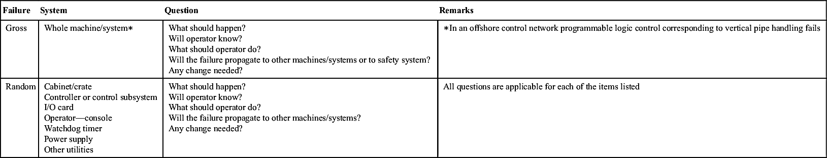
Inspired by S. Yanag, W.H. Chung, Hazard analysis and support tool for computer controlled processes, Loyuborough University, Journal of Loss Prevention in the Process Industries, 1998; Elesevier.
Table IV/1.5.4-3
| Signal/Actuation | Deviation | Question |
| Signal | Low | Does it matter? Will the operator know? Action required by operator or other system? |
| Signal | High | All above questions applicable here also |
| Signal | Drifting | All above questions applicable here also |
| Signal | Invariant | All above questions applicable here also |
| Signal | Bad | All above questions applicable here also |
| Actuator | Driven failure high | All above questions applicable here also |
| Actuator | Driven failure low | All above questions applicable here also |
| Actuator | Drive stuck | All above questions applicable here also |
| Actuator | Drive drifting | All above questions applicable here also |
Inspired by S. Yanag, W.H. Chung, Hazard analysis and support tool for computer controlled processes, Loyuborough University, Journal of Loss Prevention in the Process Industries, 1998; Elesevier.
Table IV/1.5.4-4
Questionnaire for Complex Control Scheme
| Complex Scheme | Points to be Considered |
| Purpose and method of operation, e.g., sequence of operation interlock, etc. | Safety-related function |
| Point of operator access | Set point/cascade make or break |
| Limit application | Careful use of limit for good safeguard and/or early warning |
| Other scheme interaction | Startup/shutdown/normal operation, timing issue, synchronization, required/expected operation |
| Controller tuning | Initialization/winding up |
| Relationship with trip and alarm—action in the event of major plant upset | Loss of utility, spurious/correct operation of emergency shutdown |
| Unauthorized access protection and others | Spreading over large system (>1 controller subsystem) |
Inspired by S. Yanag, W.H. Chung, Hazard analysis and support tool for computer controlled processes, Loyuborough University, Journal of Loss Prevention in the Process Industries, 1998; Elesevier.
1.5.5. CHAZOP Procedure (Outline)
General brief outlines are discussed here. It is recommended that both preliminary as well as full CHAZOP are carried, so both the systems have been included in the discussion.
• Preliminary CHAZOP: This is undertaken at the early stage when not enough documentation is available. The following issues are addressed:
• Overall proposed system architecture including functionality of the system is discussed. In this the following points are taken into account:
– Machine/main system
– Basic functions of all subsystems
– Redundancy criteria
– Diversity factor
– Protection issues
– Both PEs as well as non-PEs
• Total review of the system including protection and interlock, alarm, and safety aspect. In this connection Fig. IV/1.5.1-2 may be referred to.
• Study of the system performance in the event of failure of main system and/or machine and/or failure of power supply and/or other utilities.
• Full CHAZOP: The main procedure is to study the system with the help of guide words and questionnaire, discussed in Clause 1.5.4 in detail. The designer presents the required information to the team in the form of various drawings and documents so that the study can be carried out. As before, such a complete failure of the machine and/or its components, etc. is studied systematically. In this connection it is to be noted that in complex control schemes it is necessary to study and monitor system performances also. For CHAZOP study purposes there are some differences in considerations between continuous process, sequential process, and batch process. The technical aspects of these differences are discussed and highlighted here:
• Continuous process: The system measurements are the continuous type, hence I/Os are continuous signals so I/O signals are checked for “bad” (e.g., signal out of range, say beyond 4–20 mADC, “transmitter accuracy” and condition, etc.). In addition to these the redundancy of transmitters is different to that in the case of pure binary type signals (switches). For controllers, tuning parameters are checked for stability and correctness as well as against changes in process conditions. Overall control philosophy, interaction with other systems and safety aspects such as safety interlock, loop performance, etc. are monitored.
• In the case of sequential controls, startup, running, and shutdown modules are checked for operator action. All critical timings (including waiting time and monitoring time) and major equipment interactions, etc. are monitored. For each sequential step module, similar considerations are applicable also. In addition to this the overall sequence activation/deactivation sequence and communications are also considered during the study.
• For batch process (see Clause 3.4 of Chapter VI), in each step (depending on applicability), the foregoing considerations need to be checked. Additionally, those discussed in Table IV/1.5.4-4 need to be considered. Checking is time-consuming but necessary as the system needs to cope up with various situations in the batch process.
For the basic concept of CHAZOP Fig. IV/1.5-1 may be referred to see that the safety system has been kept separate from BPCS, to give backup in case of BPCS failure. At lower levels, redundancies with fallback facilities have been considered at controller as well as at field level. There are a few issues such as ambiguity, incompleteness, nonsensicality, and redundancy that are very much present in conventional HAZOP and should be avoided prior to applying data from HAZOP directly to CHAZOP. On a case-by-case basis, there may be additional factors to be considered for CHAZOP. It will be prudent to consider only those combinations that will give meaningful deviation, and repetitive combinations should be avoided to limit the time and fatigue in discussions.
1.5.6. CHAZOP Discussions
From the foregoing discussions it has been seen how safety aspects are dealt with in various layers and redundancies. Here, failures are taken into account, but control logic is not handled explicitly. There are no means to verify the logic requirements. For hazard analysis it is necessary that process is well represented. In the process and related controls, safety subsystems must be identified and suitable logic built for the safety system. It should be possible to verify the safety logic. In safety logic, all safety critical events shall be identified and then a questionnaire for the safety critical events shall be applied over the entire life cycle, as shown in Fig. IV/1.5.6-1.
P&IDs are the starting point in most cases but they can at best give the structure of control systems. Control logic and plant behavior are not clear from P&IDs. Some use a signed directed graph (SDG). An SDG consists of nodes to represent process variables, and a signed directed branch symbolizing the relationship of variables. However, this can only give the qualitative relationship of variables in the process. There is another method, known as event time diagram (ETD), that gives components of computer system hazards, that is, I/O levels, communication, and the computer with which control logic components are related. The process control event diagram (PCED) by Chung and Yang takes the advantages of SDG and ETD to complement P&ID for CHAZOP. In this diagram, intervention level by operator, HMI display, communication, main processor (/controller/computer), sensor actuator, and the various process divisions are shown at various levels. All control logic components are related to these with the help of arrow heads to represent actual control logic, which can be verified in the diagram. After identification of control logic, it is necessary to discover what can go wrong and its effect. Following HAZOP principles, deviations are found from each control action in the PCED [3]. If control logic under certain deviations does not satisfy safety requirements, then these are safety critical events for which necessary questionnaires are used to identify deviations and then necessary steps are taken to control action. These questionnaires will be separately filled in for each of the generic objects such as HMI, communication, sensor, actuator, process, etc. For each of these objects there will be different stages like design, implementation, operation and maintenance, modification, etc. In this connection Fig. IV/1.5.6-2 may be referred to. All these questionnaires will help to pinpoint probable events and accordingly control actions may be taken. Details can be found in Ref. [3]. This process is in theory very easy but in reality it is not so, especially for complex systems. Also for large plants it is time-consuming and costly. So, efforts have been made to automate the system. Now, we will look at the intelligent HAZOP system.


1.6. Intelligent HAZOP (HAZOP Automation—The Concepts)
As discussed earlier, the time and cost for HAZOP analysis is quite large, especially for complex/large plants. Automation in HAZOP is capable of reducing both time and costs. Also it can provide a detailed and consistent report free from human error. Since much time and effort are saved, the team members can concentrate more on complex plant issues. Also it is possible to integrate various other technical programs, for example, computer aided design (CAD). There are a number of issues to be addressed before automating HAZOP. Some of these issues shall include:
• Generic/general approach for plant hazards
• Different approach toward control/computer system (see Clause 1.5)
• Recognition of the different approaches for continuous plant
• Approach difference for batch process
• Inclusion of plant-specific data such as:
• P&ID
• Material property
• Combining general system with plant-specific data to:
• Find abnormal causes
• Find adverse consequences
• Assess hazard propagation
It is quite some time since various methods were developed for automating the HAZOP process. Some methods included computer-based systems. We shall now see how these systems have been developed.
1.6.1. Short Discussions on Developmental Process
Back in 1987, Parmer and Less developed a rule-based approach for automation of HAZOP. They developed knowledge representation regarding the propagation of faults/failures from each of the process units, such as pumps, heat exchanger, etc. They tried to include control systems such as sensors, control valves, controllers, etc. In this method they partitioned P&ID into several sections. In one section, a line was chosen for hazard analysis. They tried to find cause from an initial event in the process unit and consequence in the terminal unit. So, hazard analysis was restricted to the limit of the line under study. This is in contrast to the HAZARD analysis principle, which continues to the end of the process. Hence it could show immediate effects/consequences. They used FORTAN language for computer programming. In 1989 Water and Ponton studied automation of HAZOP through their simulation approach. For practical application, on account of its complexity, it did not become so popular. The rule-based approach was also introduced by Heino and Suokas in 1990. They developed rule-based logic to search for the cause and devised it in “If deviation type” and condition is like that… then probable cause will be… Naturally, in industrial applications, where there are so many possibilities, there will be too many rules to search for a cause. As a result this approach was difficult to handle. Also here, cause has more importance than consequence, which is the opposite in the normal HAZOP approach. A modeling language for chemical process and reactions was developed by Henning and Leone in 1990. This was mainly applicable to chemical processes involving reactions. Nagel in 1991 developed inductive and deductive type rules for hazard identification in chemical reactions in chemical plants. The rules although ideal for chemical processes involving complex reactions were not widely used for general industrial applications. In 1994–96 Venkatasubramanian and Vaidhyanathan developed an object-oriented model based on HAZOP expert systems with different approaches for continuous and batch processes. In 1997 Dimitradis, Shah, and Pentelides developed a quantitative approach toward HAZOP automation. In this approach it was necessary to identify the disturbance profile leading to hazards. In many cases, especially with nonlinearity, it was difficult to solve the problem. In the same year Faisal and Abbasi produced TOPHAZOP, a knowledge-based two-compartment general and specific software tool for projects. Objects, attributes, causes, and consequences were included in the model. While objects are developed in a frame structure with their attributes, causes and consequences are generated through rule-based systems by combining the rule with the framework. In 1998 Srinivasan, Shah, Dimitradis, and Venkatasubramanian developed a hybrid knowledge-based mathematical model, and in 1999 Turk developed a discrete model to capture hazards in continuous and sequential chemical process. In addition, there have been several other approaches for automating HAZOP: McCoy (1999), Bartolozzi (2000), Kanga (2003), and Zhao (2005). Of these the HAZOP expert-based system is applicable in a generalized way and is more acceptable on account of its quick process. However, this system requires a huge database and it is not very easy to integrate with CAD. In subsequent clauses, expert system, P&ID integration, and model-based systems will be touched upon. However, wide use of automated HAZOP in industrial scenarios has a long way to go! Some of the developments in this area will be highlighted in later clauses, enabling the reader to grasp some knowledge of automated HAZOP. Digraph shown Fig. IV/1.6.1-1 is often used in automated HAZOP.

1.6.2. HAZOP Expert
HAZOP expert is an object-oriented model-based intelligent technique used to automate the HAZOP process. It is well known that no two plants are identical, hence the problems will be different. At the same time it is also true that the majority of time and effort is spent on routine work in a HAZOP study and there is commonality in this routine work. So, by automating this routine part (which is a major part), time, effort, and cost can be saved. But how can this routine work be matched with plant-specific issues? Another important issue to be noted is that automation is not meant to replace the HAZOP team but to supplement it, so that experts instead of being bogged down with routine work can concentrate on how to address the complex issues pertinent to the plant. To understand HAZOP expert it is better to refer to Fig. IV/1.6.2-1.
• Description: HAZOP expert is a HAZOP digraph model-based system. The digraph represents the plant process with the help of a directed graphical model in which ways and means, that is, knowledge to identify abnormal causes and adverse consequences, have been built in. The HAZOP digraph is built in a context-independent manner to cover a wide range of applications. The following discussions shall be read in conjunction with Fig. IV/1.6.2-1. The key part of the model is the graphic user interface (GUI), which consists of three subparts, namely, material and P&ID editor, HAZOP digraph model developer, and reporting section. Details of the subsystems of the GUI can be found in Table IV/1.6.2-1.
Once P&ID and material data are inputted, then the associated HAZOP model for the particular plant is generated with P&ID (inputted) connected automatically and ready for HAZOP analysis. So, a lot of knowledge acquisition time and effort are saved. The user can initiate HAZOP analysis in any line in the P&ID. The next part is Knowledgebase, which could be an Microsoft (MS) Access database consisting of information derived from old HAZOP analyses, related to process operation, associated process units, operating issues, failure modes and conditions, etc. Knowledgebase consists of two parts: generic and project specific. Knowledgebase is capable of suggesting probable solutions. Knowledgebase directly communicates with the GUI to help the user to carry on HAZOP analysis. The third part is the inference engine, which is like a search engine. It has a fault propagation algorithm, which in conjunction with Knowledgebase helps the user to retrieve the generic and specific abnormal causes and associated adverse consequences. This deviation propagates from the starting process unit to the end equipment, as defined by the user through the GUI. The user accesses the system through I/O units, as shown in Fig. IV/1.6.2-1.
• Discussions: In manual HAZOP it is very difficult, if not impossible, to consider process variable deviation in each pipe valve, etc. Normally, it is grouped and put in a node to study. Naturally, in HAZOP expert, there will be many more deviations generated when compared with the manual counterpart. So there is less/no chance of missing an issue because of human error. These are all positive sides, but there is a negative side also. In manual HAZOP, many of the useless causes and consequences are filtered out at the beginning, on account of specification, operating condition data, etc. In this system there will be so many unnecessary causes and consequences. As a result people are now thinking of utilizing a semiqualitative type so that unnecessary causes and consequences generated because of pure qualitative methods can be avoided.

Table IV/1.6.2-1
Graphic User Interface (GUI) Subsystems
| GUI Subsystem | Function | Remarks |
| Material and P&ID editor | The piping and instrumentation diagram (P&ID) editor is meant to develop P&IDs∗ specific for the plant with the help of the editor. The material editor is used for inputting material property data (such as flammability, toxicity, corrosion, etc). In case these data are available in any database then they can be imported. | ∗Direct import of P&ID in computer aided design (CAD) is possible. |
| HAZOP digraph model developer | The model library has generic models for various process units and control systems such as process pump, heat exchanger, tanks, vessels, pipes, valves, controller actuator, etc. | |
| Report generator | The basic function of this is to generate reports in a desired format. |
• Batch process (see Clause 3.4 of Chapter VI): Batch process is quite different from continuous process, for example, in continuous process there is hardly any direct role of the operator in the process steps. In continuous process the operator controls, monitors, and diagnoses faults in the process. On the contrary, the operator has a great role to play in processing steps. There may be the requirement of a subtask initiation by the operator. Any omission or wrong operation such as wrong sequence selection, wrong duration selection, even wrong material selection can lead to process hazards in the batch process. Unlike continuous plants, batch process is both discrete and characterized by a temporal nature. Plant status changes with time in a defined sequence. P&ID cannot totally describe and get a full idea of the plant. So, it is necessary to have an instruction sheet and sequence chart both of which form the recipe. HAZOP in batch process mainly concentrates on finding plant maloperation and process variable deviation. A model-based expert system for automating HAZOP is referred to as HAZOP expert. Batch HAZOP expert (BHE) architecture is similar to what has been discussed for continuous process and includes:
• Knowledge of the organizational framework (expert system)
• Inference mechanism
• Graphical user interface comprising:
• P&ID graphical editor
• Product recipe graphical editor
• Process chemistry editor
• Subtask digraph model editor
Two terms are important here: Recipe Petri net, which describes the sequence of various tasks, and Task Petri net, which defines the sequence of subtasks within a task. For each subtask there is one digraph model built to get a cause and effect relationship between the associated variables. These are shown in Fig. IV/1.6.2-2. For Petri net definition Fig. IV/1.6.2-3 may be referred to. Fig. IV/1.6.2-2 shows Petri net knowledge base representation of a recipe with a number of tasks and subtasks. Each subtask is then a digraph model for HAZOP analysis. Plant maloperation can be generated by using this figure.
Semiquantitative reasoning with required information like operating parameter, hazard critical data for equipment, and materials is used to filter out less possible consequences. For a Petri net task with too many subtasks, it is always better to go for HAZOP expert for filtering and ranking the consequences.


1.6.3. LDG HAZOP Automation
HAZOP expert discussed earlier has wide application, but for success it depends too much on a database. Also actual integration of CAD P&ID into the system is not so easy with normal P&ID, which depends too much on drafting, and manual input of process-specific data invites human error. It is now possible for various software packages to have a communication link to other external software packages. So, Intergraph's Smart Plant P&ID (SPPID), which is an asset-centric rule-driven CAD P&ID, is very helpful in integrating P&ID into the computer system. It depends more on plant data than drafting. This is helpful in exchanging specific plant data into the system. From this, an initial model based on signed directed graphs (SDGs) was developed. It had a few shortcomings. Subsequently, a layered directed graph (LDG) model-based HAZOP expert system (LDG HAZOP) was developed to overcome the shortcomings of SDG. The LDG model qualitatively highlights cause and effect relationships between process deviations with the help of HAZOP guide words. Here also a user interface with the system with the help of an I/O system at the user interface module is directly linked with document (DOC) and LDG modules, as shown in Fig. IV/1.6.3-1.
LDG qualitatively tries to find cause and effect relationships between process deviations generated by HAZOP guide words. LDG HAZOP is a web-based multiclient expert system for HAZOP developed in Java language [4]. The main subunits connected to the user interface are the DOC and LDG modules. The DOC module is mainly used for the word processing unit. DOC modules consist of (1) result/report generation subsystems, (2) a document management subsystem, and (3) a hint generator.
Various submodules of the LDG module are as follows:
• LDG library: LDG modules of various process units it is somewhat like general knowledge base in HAZOP expert discussed earlier.
• Process description (PD): PD of the process in the question is inputted to generate a process-specific database. (This can be compared with project-specific interface in HAZOP expert.) Based on data defined by PD, an algorithm is developed to match a model in the library. Equipment interconnections are done based on process-specific data in this module.

• Reasoning machine: This is used to start an automatic HAZOP study, after LDG models are properly linked.
• In the next stage, human validation and modification is done.
• Reference base (REF base): A DOC module can generate a report by directly importing REF base when desired by a human expert. It also generates intelligent hints. A similar function was also present in HAZOP expert.
SPPID interfaces LDG module through PD, as shown in Fig. IV/1.6.3-1. Thus it is possible to directly import project-specific data from SPPID.
1.6.4. Multilevel Flow Modeling-Based System
Another way HAZOP can be automated is by multilevel flow modeling (MFM). MFM is described in Fig. IV/1.6.4-1 and it is widely used in risk analysis.

MFM is capable of representing functional knowledge with an easier understanding of the process. It could provide an efficient paradigm for facilitating HAZOP studies and for enabling reasoning to identify potential hazards in safety critical operations. MFM is a qualitative reasoning model that could be used to assist the HAZOP team by ensuring coverage and consistency. MFM divides the system into subsystems according to the functions in terms of goals, relations, and process units. MFM provides a set of reasoning rules that can be used to perform an automatic HAZOP study and reveal the potential hazards and casual paths of a hazard in a visual way.
A typical automated HAZOP study principle-based method is shown in Fig. IV/1.6.4-2. MFM is a functional modeling method, used to represent goals and functions of process plants that involve interactions between flows of material, energy, and information. Various representative symbols typically used in building an MFM model are shown in Fig. IV/1.6.4-2B. As shown in Fig. IV/1.6.4-2, qualitative reasoning in an MFM model is based on representation of process knowledge. The rule-based interference engine is used to find causes and consequences pertinent to hazards. With slight modification the same model can be used for similar plants. Another unique feature of MFM is that it can be applied to control systems to identify the hazards.

Now, efforts have been made to develop suitable software for various methods of plant (process) hazard analysis (PHA). There are a number of papers available where through suitable software it is possible not only to automate one PHA method but to integrate several automated PHA methods such as event tree/fault tree (Chapter V) with HAZOP or HAZOP with FMEA, which will be discussed in the next clause in this chapter.
..................Content has been hidden....................
You can't read the all page of ebook, please click here login for view all page.