Chapter XI
Fault Tolerance, Protection Layer, and System Security
Abstract
A safety instrumentation system (SIS) demands a fault tolerant design to ensure high availability and system integrity. The discussions on fault tolerance cover various fault tolerant measures, including fault tolerant characteristics, redundancies, and hardware and software. The discussions start with faults and failure types along with other related issues like availability, maintainability, and countermeasures suitable for each. Discussions are completed with a focus on fault tolerant networks including fault tolerant Ethernet. Minute details on independent protection layer characteristics and their effect on SIS are covered. The role of a firewall and demilitarized zone in combating a cyber attack is very important and discussions on these are included. In view of current demands for commercial off-the-shelf and integrated networks, cyber security is extremely important and special discussions on these are necessary because cyber security of industrial automation and control systems is different from information technology cyber security. Special discussions are included to focus on zone conduit and Open Platform Communications firewalls in line with the upcoming international standard ISA/IEC 62443 series.
Keywords
Black channel communication; Byzantine failure; Common protocol; DMZ; Dynamic recovery; Fault tolerant network; Fault tolerant unit; Firewall; Graceful shutdown; Man in the middle; Security level; Zone conduit
It is needless to argue that the common goal for everybody today is to have a reliable system that can tolerate or accept single or multiple failures as long as the system is not degraded or the required operation is not disturbed. Reliability is therefore a necessary goal of a system and is set by designers and users depending on the type of system in question. Different applications have different requirements for reliability, availability, recovery time, data protection, and maintainability. So, there exist different fault tolerant techniques, layers of protection, and security arrangements to increase system safety reliability and availability. During the discussions on safety integrity level (SIL) it has been seen that different SILs demand different fault tolerances. Apparently, it may appear that by increasing redundancy the fault tolerance can be increased. This notion is not always true. Also an increase in redundancy will call for higher cost. Therefore one needs to concentrate on how, by designing fault tolerant control and computing systems, system availability as well as reliability and safety can be increased. The fault tolerant design of control and computing systems is a vast issue and is dealt with in this chapter only briefly. Layers of protection have a direct impact on the SIL of the system. So, additional aspects of SIL will be covered in this chapter. As stated earlier, today's control systems are based on real-time computing systems that allow networking and integrating of different systems, which make system design and control more economic and easier to handle. There is a flip side to this success: the system will become vulnerable to cyber attacks. “Open-based standards have made it easier for the industry to integrate various diverse systems together, it has also increased the risks of less technical personnel gaining access and control of these industrial networks” (courtesy National Communication Systems Bulletin) [2]. So, network security demands special attention. In this chapter, brief discussions on network security and firewall arrangements are also covered. Let the discussions begin with fault tolerant design.
1.0. Fault Tolerance
Let us first examine the two words “fault tolerance.” One can define fault as an incorrect step, process, or data function, etc., meaning that it is the malfunction or deviation from an expected result or behavior. On the other hand, tolerance stands for endurance, in this case, continuance of operation even after a fault has occurred. So, the two words together stand for the ability of the system to function even after a fault(s). To start with it is better to define the basic terms that will be used in subsequent discussions.
1.0.1. Definition of Terms
The following are definitions of a few commonly used terms:
• Error: Error can be defined as the deviation from correctness or accuracy. Since it is associated with certain values, it can be alternatively defined as the difference in the result of a computation and correct result.
• Failure: Failure is the nonperformance of some action that is due or expected. The result of a fault could be failure. Error leads to failure or failure may be an effect of error.
• Fault: Fault may be defined in various ways:
• Fault: Fault in a system is defined as some deviation from the expected behavior of the system—a malfunction.
• Fault can be defined as an incorrect step, process, or data definition in general terms.
• In terms of computing fault can be defined as the deviation of one or more logic variables in computer hardware from a specified value.
• Fault tolerance: Fault tolerance is the property by which a system continues to operate properly in the event of the failure of (or one or more faults within) some of its components.
• Fault tolerant design: A system that is designed with fault tolerance philosophy is basically a fault tolerant design. So, a fault tolerant design enables a system to continue its intended operation uninterruptedly and/or at a reduced level, rather than failing completely, when some part(s) of the system or component(s) fails. Also in a fault tolerant design, if the operating quality decreases at all, then the decrease is normally proportional to the severity of the failure; this is in contrast to complete failure of the system for a nonfault tolerant design. The most common example to understand this is the running of a car. When the tire of a car is punctured, the car can run but at a lower speed (of course there is the possibility of the wheel rim being damaged) for some distance. If the puncture is slow the speed reduction may not be appreciable (i.e., proportional to fault). There are fault tolerant designs where designers provide redundant components, and there are cases where redundant computers are used. Such designs are called fault tolerant architecture. In cases of information and communication systems there is another popular term called fault resilient design (which often considered as economic version of fault tolerant design, where only critical parts are duplicated). The main purpose of a fault tolerant system is to develop a system that is dependable. Fault tolerance is a means of dependability (see Clause 1.0.2).
• Fault tolerant unit (FTU): FTU is a part of fault tolerant design. A device (maybe a controller) continues to operate even in the presence of faults. This is achieved primarily by using replication of hardware, software information, and time. In control applications there are two types of FTU, node oriented and application oriented.
• Node-oriented FTU: In computer architecture nodes normally operate independently for their associated application. In a node-oriented FTU, there is replication of the node(s). In case of failure of the primary node, the designated replicas of the primary nodes will take over with a necessary mechanism to allow just one replicated unit to take over to avoid collisions or contention [9]. There are a number of boiler controls in a power plant, namely, a closed loop control such as a superheater temperature control, furnace safeguard and supervisory system, high pressure bypass, etc., each with different apparently independent applications. In node-based architecture, there may be FTUs for each of these control systems acting as one node. In a particular node, when one of the main units fails any one of the standby controllers takes over irrespective of the application. Here the major concern is the size and capacity, and also the changeover mechanism.
• Application-oriented FTU: The units of replication in an application-oriented FTU are also nodes belonging to a common pool of redundant nodes defined for a specific application. When the primary node fails, only nodes that are designated replicas of the application to which the failed node belongs will take over [9]. There are separate controllers for boilers and turbines. Similarly, each of them may have separate subsystems for application processing. Now, if any of these application processors fails, one application-oriented FTU from a common application processing subsystem can take over the function so that the entire system continues to operate uninterrupted.
• Graceful failure/shutdown: A system that is designed to be fail safe or fail gracefully means that it functions at a reduced level or fails completely, and does so in such a way that it protects people, property, or data from injury, damage, intrusion, or disclosure. Normally, a distributed control system (DCS) is designed in such a way that even it fails for some reason, data are not lost, so that it can be started after it is functional or part repaired. It is common that in the case of power failure, with a trailing edge below a certain value, computing systems save all necessary data so that they can be started when power is available.
• Failed deadly (see http://en.wikipedia.org/wiki/Fail-deadly): Fail deadly is the opposite strategy of graceful failure, which can be used in weapons.
1.0.2. Dependability
Dependability is the ability of a system to deliver its intended level of service to its users [5]. Also it can be conceived as the reliance on a system for the quality of services it provides during an extended interval of time. There are attributes, measures, means, and impairments pertinent to dependability. Fault tolerance is one of the means of dependability, as shown in Fig. XI/1.0.2-1. Various contributing factors as shown are elaborated in the following:

• Attributes: There are three major attributes of dependability to signify the properties expected of the system. These are briefly discussed as follows:
• Availability: Availability A(t) of a system at time t is the probability that the system is functioning correctly at the instant of time t, where A(t) stands for instantaneous availability. The interval of availability is given by:
![]() (XI/1.0.2-1)
(XI/1.0.2-1)
At steady state it shall be:
![]() (XI/1.0.2-2)
(XI/1.0.2-2)
For further details see Clause 1.1.4. In this connection two other terms are also important: “probability of failure” and “mean time to repair” (see Chapter VII).
• Safety: Safety S(t) of a system at time t is the probability that the system either performs its function correctly or not in a fail safe manner in the interval [0, t], given that the system was operating correctly at time 0. The issue here is fail safe operation or not.
• Reliability: As already discussed in earlier chapters, given that the system was performing correctly at time 0, reliability R(t) of a system at time t is the probability that the system operates without a failure in the interval [0, t]. Reliability is a measure of the continuous delivery of correct service.
• Measure: All these attributes need to be suitably measured to get an idea of the dependability of the system. Major issues like availability, safety, and reliability were discussed earlier and hence are not repeated here. Apart from these there shall be a few other measurable issues such as performability, testability (self-explanatory), and maintainability.
• Performability signifies how the system performs with respect to dependability.
• Maintainability: This is the probability of a system/subsystem being repaired. Major factors affecting maintainability shall include but are not limited to the following:
∘ Troubleshooting and troubleshooting tools
∘ Fault diagnosis and isolation
∘ Fault alarms
∘ Training of personnel
∘ Accessibility
∘ Addition and removal of components
In various intelligent systems, maintainability has reached such a position that it is possible to perform online addition/removal of cards, partial editing of programs, as well as diagnostics via fieldbus systems/Highway Addressable Remote Transducer (HART) [6].
• Means: There are several means for dependability. Fault tolerance is one of them and was defined earlier. The other means are:
• Fault forecasting is a set of techniques for estimating the number of faults, possibilities of occurrence in the future, as well as their consequences. This evaluation can be qualitative or quantitative. The former technique only ranks them. The following are the issues here:
• Fault prevention techniques: These are aimed at preventing the introduction or occurrence of faults in the system. Fault prevention is achieved by quality control techniques during the specification, implementation, and fabrication stages of the design process. Design reviews, component screening, and testing (burn-in, power supply failure, etc.) used for hardware are also types of prevention technique. For software, structural programming, modularization, and formal verification techniques are used.
• Fault tolerance: As defined earlier, fault tolerant designs are aimed at development of systems that could function correctly in the presence of faults. This is primarily achieved by some kind of redundancy to detect or mask a fault. Masking/detections are followed by fault location, containment, and recovery.
• Fault removal: Fault removal techniques are used for reduction of the quantity of faults during the developmental phase as well as during the operational life of a system:
∘ Developmental stage: Verification, diagnosis, and correction.
∘ Operational stage: Corrective and preventive maintenance.
• Impairment: This consists of fault, error, and failure, as already defined. The relation between them is detailed in Fig. XI/1.0.2-1. These are dealt with in detail in subsequent subclauses.
1.1. General Discussions on Fault Tolerance
Here, general characteristics and features of fault tolerant designs are discussed.
1.1.1. Characteristics
The following are general characteristics found in fault tolerant systems:
• High availability, no single point of failure: When a system experiences a failure, it should continue operation without interruption during repair, that is, failure recovery.
• Fault isolation of the failing component: The system should be able to isolate the failure and there should be a number of dedicated failure detection mechanisms for fault isolation. Recovery from a fault condition requires classification of the fault or failing component.
• Fault containment and prevention of failure propagation: The system needs to have a mechanism for fault containment to prevent fault propagation. Firewalls or other mechanisms are examples.
• Availability of reversion modes
• Planned and unplanned service outage
1.1.2. Fault and Failure Types
The most important characteristic of fault is duration. So, fault can be classified utilizing this characteristic feature. Based on duration, the fault can be classified as a “permanent/solid/hard” fault and a “transient/intermittent/soft” fault. In most systems the majority of faults are transient faults (above 80%). Transient faults, or intermittent faults, can be defined as random failures that prevent the proper operation of a unit for only a short period of time—not long enough to be tested and diagnosed as a permanent failure.
• Permanent faults: Permanent faults are caused by failures of components. This type fault is persistent and continues to exist until the faulty component is repaired or replaced. These faults are easier to diagnose but normally require more rigorous correction than transient faults. A computer disk crash is an example.
• Transient/intermittent faults: Transient faults occur once and then disappear. The majority of DCS or computer system faults (80–90% [4]) are the transient type, for example, a message is sent but does not reach the recipient, but when it is resent, it reaches the recipient. There is a peculiar characteristic of transient faults. This is termed intermittent fault, which occurs and vanishes in a cyclic manner. A simple loose connection in a component can cause such a situation. Transient and intermittent faults are mainly caused by random failure of components and the faults stay for short while and are then diagnosed or tested. It is quite possible that transient faults become permanent with further deterioration of the equipment.
From discussions in Chapter VII it is seen that there are mainly two types of failure: “random” and “systematic” [common cause failure (CCF) can be either of these]. Here, the faults discussed are caused by random failure. In an electronic system, especially in a computing system, two special types of failures are encountered:
• Fail silent failure: When the system either stops producing output or produces output that clearly indicates that the component has failed.
• Byzantine failure: This is derived from the Byzantine general rule/problem (Fig. XI/1.1.2-1). Here, the faulty unit continues to run but produces incorrect results. Byzantine fault is difficult to handle.
As discussed earlier, the aim of system reliability is to forecast/prevent/recover from faults. So, to achieve a high reliability, it is essential that components be highly reliable and there is high immunity to software fault induction into the system. Therefore fault tolerant computers need to use proper selection of redundancies, as discussed in the next subclause. There can be other faults like hardware/software design fault, operator error, physical damage, etc. However, most fault tolerant design deals with random hardware faults.

1.1.3. Redundancy
Before starting discussions it should be made clear that fault tolerance may be aided by redundancy, but redundancy and fault tolerance are not the same. Redundancy does not ensure continuance of operation of a system. In the case of the previous example of the car (Clause 1.0.1), if the car tire bursts, then one needs to stop the car and change the tire before continuing. Here, there is a redundant tire, which can be used, but car has to stop before the operation can continue. On the other hand, if fault tolerant design operation is uninterrupted, for example, in a programmable logic controller an uninterrupted power supply (UPS) is used if the main supply fails, output of the UPS is unaffected or a hot standby processor can continue the operation of the PLC. Most of the instrumentation and control systems currently in use are intelligent types comprising hardware and software. So, to achieve a fault tolerant design both can be utilized. There two types of redundancy, namely, hardware redundancy and software redundancy. When retrial of instructions in a computer system is done it is time redundancy [4].
• Hardware redundancy: In hardware redundancy a set of hardware components needs to be introduced into the system to provide fault tolerance with respect to operational faults. These components are a duplication or triplication of the original set of components; hence when there is no fault these are superfluous or redundant. Obviously, removal of the components in the absence of faults has no real impact on system performance. As discussed earlier, for hardware fault tolerance, the most reliable components available should be used. However, increased component reliability has hardly any impact on fault tolerance if the fault is an operational one. Hardware redundancy is more important in recovery than in prevention.
• Software redundancy: Software redundancy refers to all additional software installed in a system to handle a fault exclusively. An intelligent system consists of hardware and software and for such a system, when there is no hardware design fault, then one of the reasons for the fault in the system can be because of a software design fault. To handle a software design fault, software redundancy is applied since it is hardly possible to handle a software design fault with hardware. In intelligent systems, software redundancy is very important, because it can be used even to handle hardware malfunctions. Based on the requirements of recovery needed, the level of software redundancy is decided. The recovery design is dependent on the type of error or malfunction. In some cases only hardware or software redundancy is sufficient for the recovery, while in most cases a mix of both redundancies is called for. When hardware fails there is the possibility that there will be a loss of data retrieval. In such cases for critical and important programs designers use redundant storage as a preventive measure for duplication of all necessary programs and data storage. This is necessary for retrieval. Also critical programs, for example, error recovery programs, are placed in nonvolatile storage with critical data in nondestructive readout memories.
Redundancy is very much related to availability, dealt with in the next subclause. However, it should be borne in mind that to attain technoeconomical benefit, redundancy must be deployed judiciously. Another issue that is often overlooked is voting pattern, which is also important for achieving better results, for example, a conventional dual redundant system can provide either availability when the voter is set to 1 out of 2, or integrity when the voter is set to 2 out of 2. Not both [1]!
• Redundancy and voting: Fig. XI/1.1.3-1 shows how a redundancy and voting system increases the fault tolerance. In the first case in Fig. XI/1.1.3-1A, output of A goes to B and then C to produce the final output. If one fails, then there will be failure of the entire system. On the other hand, in Fig. XI/1.1.3-1B, each item has three-way redundancy (e.g., for A it is A1, A2, and A3). In each case good ones are selected via voting circuits. This is a typical triple modular redundancy (TMR). If in place of three there are N numbers of such selection, then voting is N-modular redundancy (NMR). In this case of TMR, in the case of a double failure (item or voting circuit) output will fail “silent fault”, whereas in the case of a single fault (in each item or voting circuit) it is a single fault tolerant Byzantine fault.

1.1.4. Availability
As discussed earlier, availability can be defined as the probability that a system is operating successfully when needed. To help make sure that products meet customer expectations, reliability can be designed using techniques such as component derating and design through Six Sigma [6]. For the Six Sigma technique Fig. XI/1.1.4-1 may be referred to. It is a common notion that the availability of a system increases with redundancy. This is partially true (think of systematic/CCF for duplicate and triplicate redundant hardware). However, when redundancy in terms of duplication and triplication is done, it obviously costs more money and chances of failure are increased. So, redundancy must be chosen judiciously along with voting logic. Also redundancy alone is not responsible for higher availability. Since availability is related to failure of devices and components there are other factors that are also responsible for higher availability. For this reason in addition to mathematical expression of availability defined in Eq. (XI/1.0.2-1), however in terms of reliability, availability can be expressed in terms of mean time between failure (MTBF), mean downtime (MDT), and mean time to repair (MTTR) as follows:
![]() (XI/1.1.4-1)
(XI/1.1.4-1)
(Assuming MDT and MTTR are the same, though there is some difference.). As MTBF and MTTR depend on many other factors like quick fault detection, etc. So, availability depends on the following factors:
• Redundancy and fault tolerance
• Diagnostics:
• Easy troubleshooting
• Easy modification and repair
• Easier maintainability
Modern field devices are intelligent with field communication, so they provide a high degree of diagnostics. Also modern intelligent control systems provide a means of fault forecasting and diagnostics and maintenance management. Therefore, with these modern intelligent devices having high degree of diagnostics, along with judicious redundancy and fault tolerant design, it is possible to ensure higher availability, which is of prime importance, especially for higher SIL systems. Concentration will now be on the original issue of fault tolerance and discussions will be focused on various techniques used for achieving fault tolerant design and recovery.

1.1.5. Fault Tolerant Techniques (Computing System)
The fault tolerant design discussed here mainly pertains to computing systems and intelligent systems for real-time computer systems such as DCS/PLC and/or associated intelligent devices. Here, the discussion is on the basics of hardware and software fault tolerant principles in computing systems, whereas that applicable to control systems is covered in Clause 1.2. Two ways in which fault tolerant designs can be developed are hardware technique and software technique.
• Hardware technique: Hardware fault tolerant designs are aimed at developing computing systems that can automatically recover from random faults in hardware components. In this type of technique, generally the computing system is portioned as modules that act as fault containment regions. Each module is backed up with protective redundancy so that, if the module fails, others can assume its function [7]. Here, suitable mechanisms are deployed for error detection and recovery. There are mainly two variations in hardware fault tolerant design, namely, the masking (static) technique and dynamic recovery.
• Masking: Fault masking makes use of redundant modules that completely mask faults within them. A number of identical modules perform the same functions, and their outputs are voted to remove errors created by a faulty module. The masking (often called static) technique, which is automatic and instantaneous, can handle both transient and permanent failures. This error correction method is transparent to the user and often to the software. Redundant components effectively mask the hardware failure effect from other components. Depending on the degree of reliability and cost, various techniques can be used. The simplest one is shown in Fig. XI/1.1.5-1. Single fault in either left or right side pair or even single failure in both pairs output will be there.
TMR is a commonly used form in fault masking. Here, the circuit uses triplicate identical main and voting circuits, for example, A1, A2, A3, as shown in Fig. XI/1.1.3-1. A TMR system fails whenever two modules in redundant modules create errors so that the vote is no longer valid. When in place of three numbers N is used, it is known as NMR.

• Dynamic recovery: Dynamic recovery is generally more hardware efficient than voted systems and can be deployed where there is hardware constraint. This advantage can be seen in conjunction with disadvantages like delay in fault recovery, lower fault coverage, and involvement of special mechanisms. Dynamic recovery is applied when a computation is running and self-repairing is required. However, higher levels of fault tolerance can be achieved with the help of dynamic redundancy. Dynamic recovery involves both fault detection and recovery. Like fault masking, spare protective redundant modules are also used. In this method, special mechanisms are used to switch out a faulty module, switch in a spare, and instigate those software actions (rollback, initialization, retry, restart) necessary to restore and continue the computation [7]. Error detecting and error correcting codes can be used for messaging also. Coding may be used to detect faults in the modules. In a single computing system this involves additional hardware and software, while in multiple computing systems it can be managed by other processors. When there is involvement of software and hardware for achieving fault tolerance, then it is called hybrid redundancy. Hybrid redundancy is an extension of TMR. In this method, triplicate modules are backed up with additional spares, which are used as a replacement of faulty modules to tolerate more faults. Voting systems require more than three times as much hardware than do nonredundant systems, but they have the advantage that computations can continue without interruption when a fault occurs, allowing existing operating systems to be used [7].
• Software fault tolerance: For software, fault tolerant design redundancies are required to mask residual design faults. Some of the issues related to this shall include but are not limited to:
• Planning software fault tolerance strategy
• Defensive programming, namely, “to do the same in many ways,” “review and test,” and “verify,” etc.
Because software fault tolerance is based on hardware fault tolerance, it is a bigger challenge. Additional software is used in computing systems for fault handling and for fault-free computation. A few major software fault tolerance techniques somewhat similar to their hardware counter parts have been enumerated below.
• N-version programming: This is similar to static redundancy. Here, independently written programs (versions) for the same functions are executed parallel and their outputs are voted at special checkpoints. Naturally, the voted data may not be exactly the same. So, criteria must be used to identify and reject faulty versions and to determine all good versions for use. See Fig. XI/1.1.5-2A.

• Recovery block scheme: There are two types of recovery block scheme, namely, forward rollback (produces the correct result by repetitive and continuous processing—it is application dependent) and backward rollback (redundant information is recorded in the process of execution and rolls back the interrupted process to the point where correct information is available, e.g., checkpoint, retry, etc.). See Fig. XI/1.1.5-2B and C.
• Design diversity: This approach is rather costly. It combines hardware and software fault tolerance in different sets of computing channels. Each channel is developed in different hardware and software in redundant mode to provide the same function. This method is deployed to identify deviation of a channel from the others. The goal is to tolerate both hardware and software design faults [7]. After developing a fault tolerant design it is necessary to validate it from a reliability point of view, discussed later.
• Other issues: With software detection, it is not possible to localize the error sources. So, diagnostic test programs are frequently used identify the module concerned. Almost all DCS have some form of diagnostic routines to pinpoint the faults as best as possible. The accuracy of such pinpointing may vary from system to system. In a fault tolerant system, the system itself initiates these tests and interprets their results, as opposed to the outside insertion of test programs by operators in other systems [4].
1.1.6. Validation of Fault Tolerance
Fault tolerant design for reliability is one of the most difficult tasks to verify, evaluate, and validate. It is either time-consuming or very costly. This requires creating a number of models. Fault injection is an effective method to validate fault tolerant mechanisms. Also an amount of modeling is necessary for error/fault environment and structure and behavior of the design, etc. It is then necessary to determine how well the fault tolerant mechanisms work by analytic studies and fault simulations [7]. The results from these models after analyses shall include but not be limited to: error rate, fault rate, latency, etc. Some of the better known tools are: HARP—hybrid automated reliability predictor (Duke), SAVE—system availability estimator (IBM), and SHARPE—symbolic hierarchical automated reliability and performance evaluator (Duke).
The design of fault tolerance is different from other fault tolerant computing systems. So discussions will now be on fault tolerance in control systems.
1.2. Fault Tolerance in Control Systems
Defects or faults in any component of the loop can develop into malfunctions. Faults are not always visible to the operator immediately, but may appear in such a way that they give rise to complete loop failure. In safety-critical applications, no failure can be tolerated [3]. Redundancies in hardware and software facilitate fault recovery. So, for increased dependability fault tolerant control (FTC) is an ideal solution. In critical controls it may be disastrous to tolerate any failure of control systems. In FTC the system continues to operate with single failure in components and/or subsystems. Also in cases of critical controls, FTC will make a controlled shutdown to a safe state in a critical situation. FTC systems use the help of redundancies in hardware and software, discussed earlier, and fault diagnostics and intelligent software to monitor health and behavior of components and function blocks and take remedial action. With these tools the faults are isolated and suitable action is initiated to prevent faults from propagating, which may cause a critical failure in the system. Before going further it is best to clarify the meanings of a few terms that will be used in FTCs.
1.2.1. Frequently Used Terms in Fault Tolerant Control
Following are a few important terms frequently used in fault tolerant control:
• Fail operational: A system that can continues to function without any change in objectives or performance after a single failure.
• Fail safe: A system that fails to a state that is considered safe in the particular context.
• Fault accommodation: This is a common approach to achieve fault tolerance. Fault accommodation is limited to internal controller changes. In this method there will be changes in controller parameters or structure to avoid fault consequences. However, the input–output (I/O) between controller and plant remains unchanged, that is, the loop is not completely restructured.
• Reconfiguration: Control reconfiguration is an approach to achieve FTC for dynamic systems. In contrast to fault accommodation, in this system there will be change in I/O between the controller and plant, because there will be changes in controller structure and parameters. In reconfiguration, the interconnections among modules are altered. The original control objective is achieved although performance may degrade [3].
1.2.2. Ways and Means for Fault Tolerance
In FTC systems certain measures are taken to combat common failures such as:
• Power failure
• Control signal failure/error
• Address failure
• Module internal failure
• Module data transfer errors
• Mistiming/failure
• Communication channel failure
• Reconfiguration faults
There has been much advancement in system design for fault tolerance, for example, the use of dual and triple redundancy in the processing unit. These (dual and triple redundancy) are quite age-old systems but quite effective in many applications.
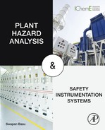
• In the duplex system, there are two identical main processing units (controllers) operating in parallel. In this parallel mode one may be active and the other may be standby or hot standby. In the case of hot standby configuration, at all times both processors are alive, in the sense that they are supplied by parallel inputs and other functions. Only the output of hot standby is inhibited, as long as the other processor is in action. In case of failure of the active processor, hot standby immediately takes over. Since the hot standby processor is always updated, transfer will usually be smooth. Each duplicated system of the processors will have internal communication with the help of parallel data and control buses, which are used for high-speed communication and interrupt handling. In the dual/duplex system there will be comparison of data for fault detection with rollback and recovery to handle transient errors [4]. To overcome the problem of comparison between two processors and resource management, there are architectures where a separate processor is used for diagnostic purposes to identify faulty processor. See Fig. XI/1.2.2-1 for typical dual redundancy processor configurations.
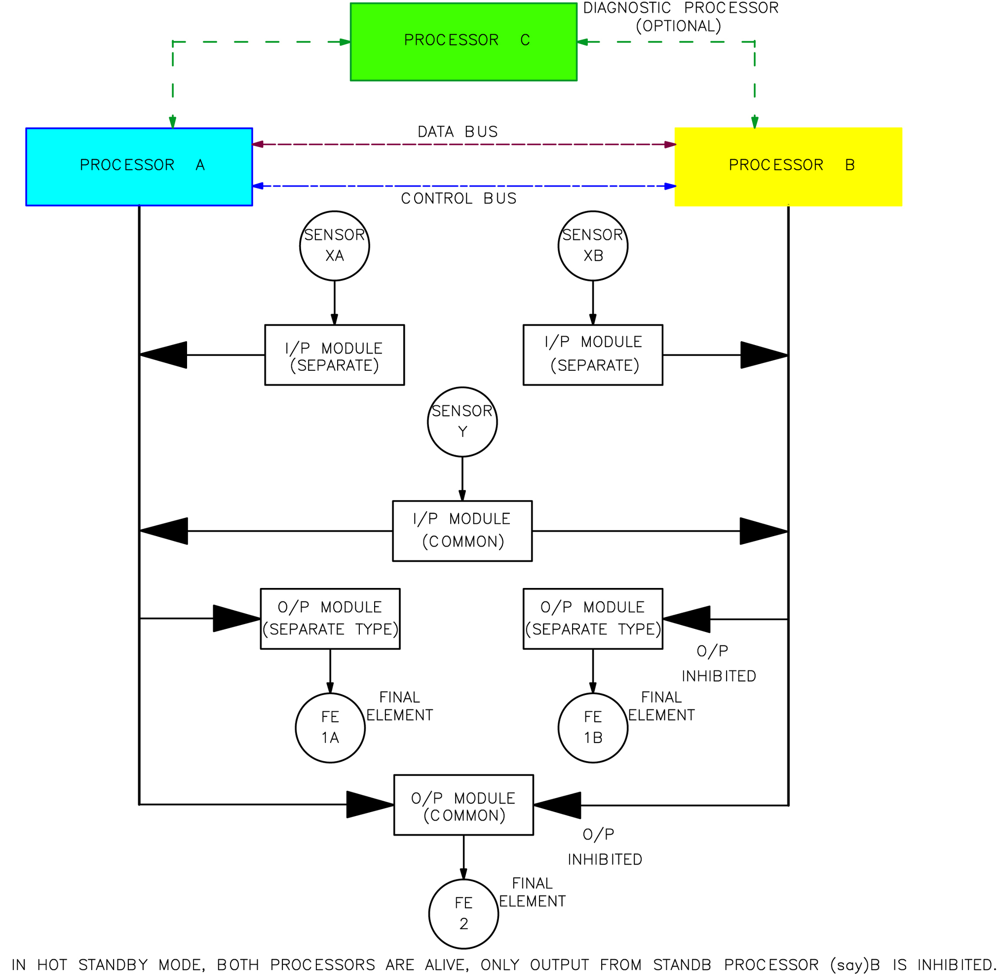
• Triple redundant system: In a triple redundant system, there will be three processors operating synchronously. In addition to error detection and correction capabilities, there will be fault tolerant features in software for both systems. Triple redundant systems have a software voting system for transient fault recovery. Naturally, there is no issue related to rollback. All computer elements will communicate with higher-level systems via a full-duplex synchronous serial bit bus, a bus that will permit simultaneous message transfer in both directions through the protocol microprocessor [4]. Fig. XI/1.2.2-2 depicts typical triple processor redundancy.
1.2.3. Practical Application
Under this clause, short discussions are provided to see how practical application in a system is realized.
• Confession and declaration: To describe the actual application of fault tolerance, internationally reputable manufacturers’ technical literature has been used and two FTCs from reputable manufacturers have been described so that readers can get a feel for the actual systems. Since the data have been taken from only two manufacturers the description may not match all systems and efforts have been made to make the data as generalized as possible but keeping the functionality intact.
• Redundant host network: A fast Ethernet network may be used as a redundant host network. This facilitates the communication medium for application development, operator interface, and data exchange among nodes. Additionally, there could be peer-to-peer communication for direct transfer of data between nodes over the high-speed Ethernet link. To handle high data traffic, only changes in data are exchanged for getting the best efficiency in peer-to-peer communications.
• Node: Many systems use separate processor modules to achieve system flexibility and performance. The node processors are responsible for all system functions pertinent to the node. The I/O or chassis processors are responsible for I/O scanning, floating point conversion, and results voting. This is a part of resource management to relieve the load of the node processor as well as to minimize the data corruption and to maximize system response required for critical controls. In this connection, processor connections pertinent to safe PLC, discussed in Chapter IX, may be referred to:
• Fault tolerance: The highest level of fault tolerant operation can be configured with redundant node processors, redundant I/O, and dual power supply chassis.
• Data integrity: Each node processor performs the system function(s) and sends the resultant outputs to the associated I/O chassis. Then the I/O processor performs data validation checking and independent voting for its associated outputs. If the system’s outputs are located in multiple I/O chassis, the voting is distributed over these chassis. Distributed voting, closed to the process, enhances integrity and makes the loop a much more responsive, high-speed system. In this connection, I/Os pertinent to safe PLC discussed in Chapter IX, may be referred to.
• High availability: In case of a hardware/network fault, the operators could be notified and the node processor could be taken offline. However, the application may continue running unaffected on the remaining node processor(s). When the error condition is cleared through online maintenance activities, nonintrusive reinitialization of the restored node processor may take place [8].
• Signal validation: Signal validation routines are supported in most of the DCS/PLC family. Signal validation routines allow for the control of one logical input produced from up to four redundant inputs (three hardware and one additional logic) [8].
• High-integrity validation: Communications are validated with the help of cyclic redundancy check (CRC) routines for main processors and the redundant I/O networks. System information is validated for remote I/O to ensure hardware availability, error -free performance. Error checking on the data transfers diagnoses data corruption. Field wiring is supervised to ensure error-free output data, I/O card diagnostics, even calibration checks on the analog/digital converters. For TMR systems, three processors may be installed in three physically separate chassis for better reliability.
• Flexible modular redundancy: This is another feature available in many DCS, for example, Siemens “Simatic PCS7.” Depending on the automation task and the associated safety requirements, the degree of redundancy may be defined separately for the controller, fieldbus, and distributed I/O level, and coordinated with the field instrumentation [10]. The great advantage of this type of redundancy is that redundancy is applied only when it is necessary. This uses the help of different types of FTUs discussed earlier.
1.3. Redundancy and Voting in Field Instrumentation
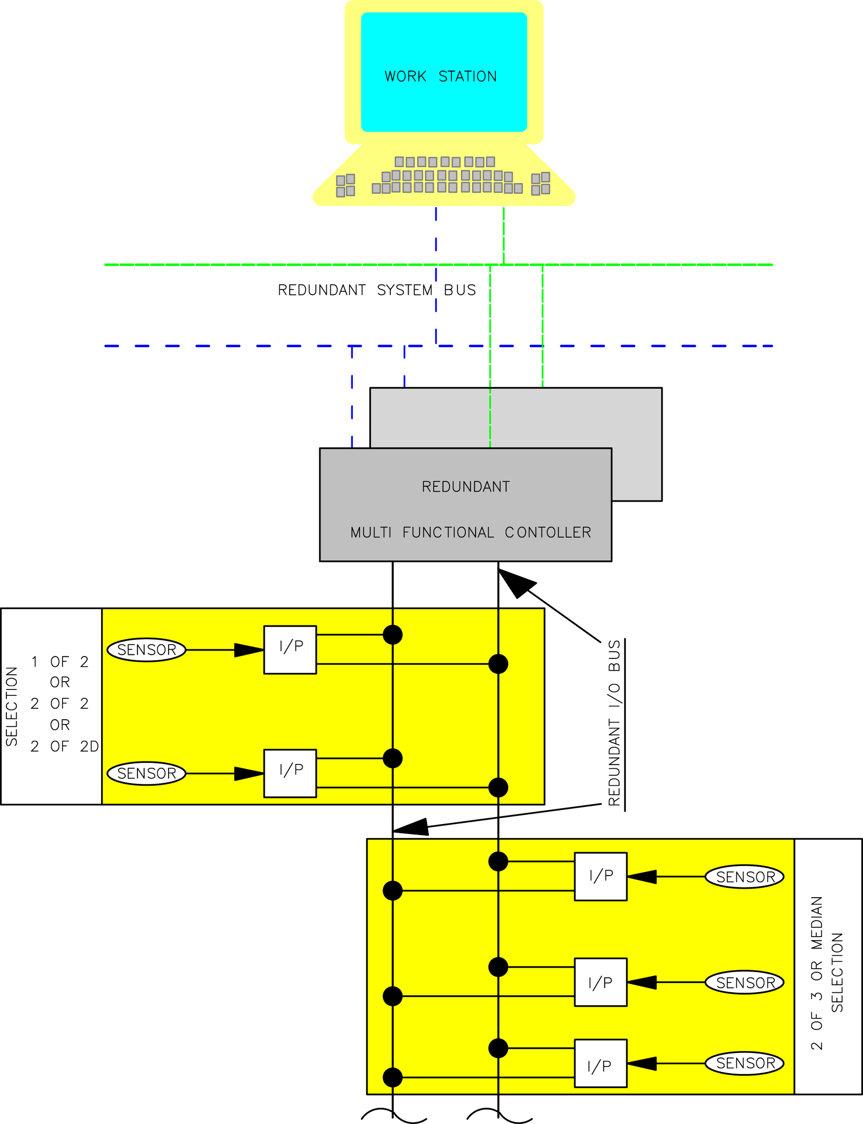
Fault tolerance in field instrumentation is mainly concerned with redundancies that in case of a basic plant control system (BPCS) ensure continuance of operation. In the case of a safety instrumentation system (SIS), they additionally minimize nuisance or spurious interventions and alarms. Redundancy in BPCS also improves safety. With properly selected and installed transmitters, improved performance can be achieved by measuring the same variable with more than a single field device. When field devices are more than 2, voting circuits are necessary. In this way “m”measurements out of a total of “n”number of signals are made so that m > n/2, for example, m = 2, n = 3, 2oo3 is the selection by voting. There are standardization of redundancy and voting techniques. Some of these are presented next. These are applied for both BPCS and SIS.
1.3.1. Field Instrument Redundancy Selection Details
In this clause, some of the typical redundancy schemes for field instruments are presented. The selection and voting circuit may be implemented in the I/O section of DCS/PLC or could be hardware. A basic selection scheme is important. For details see [2].
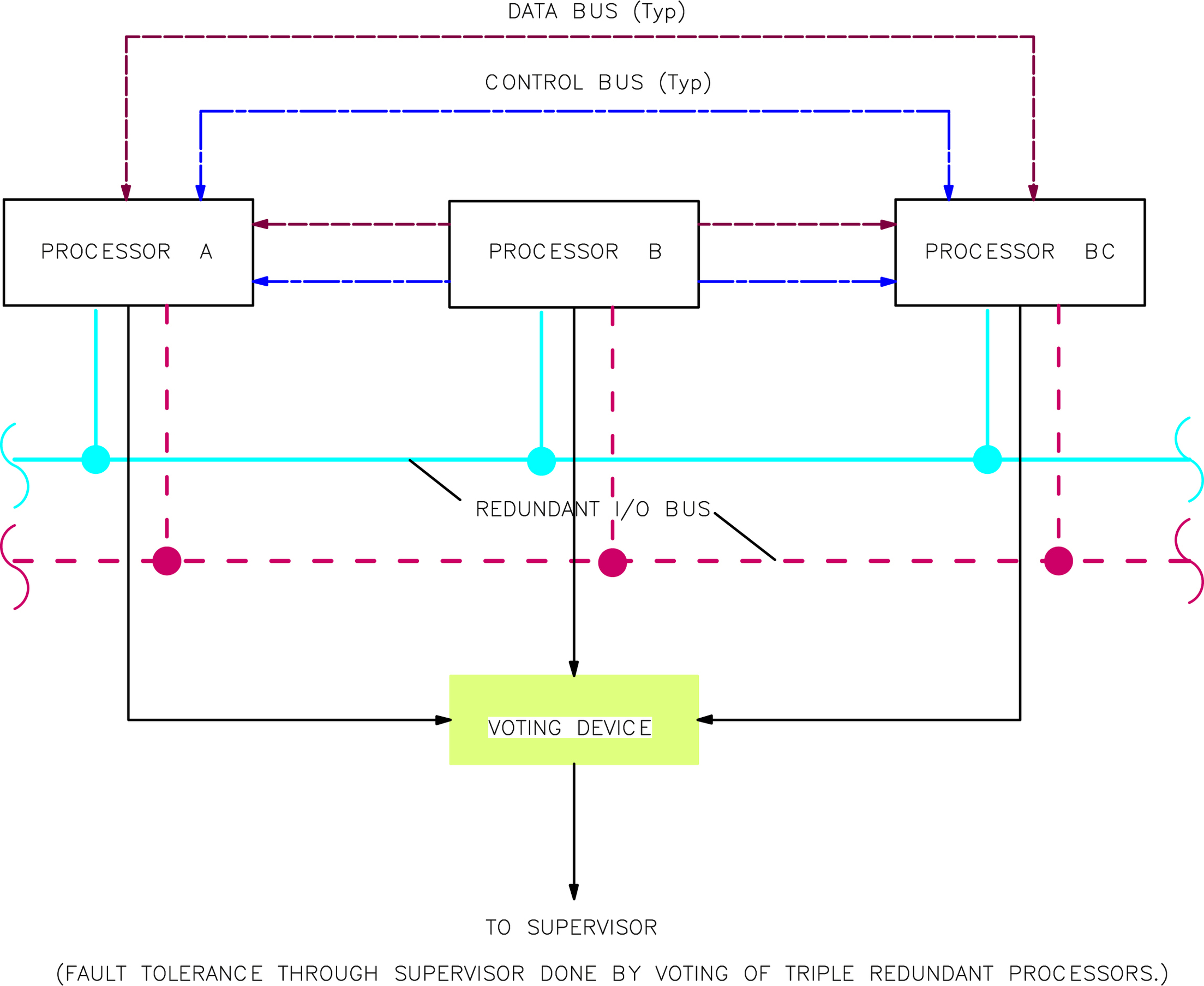
Some typical schemes of 1oo2 and 2oo3 are presented in Fig. XI/1.3.1-1.
High and low limit checks for transmitters have been in practice for quite some time, even when discrete instrumentations were in use. Now with the DCS it is very easy to monitor out of limits for the transmitter and open-circuit and short-circuit tests for sensors like resistance temperature detectors and thermocouples. Most of the transmitters are monitored for out of span (e.g., <4 or >20 mA). Also since smart transmitters have a diagnostic system, they also can detect faults and isolate them, that is, the output of a faulty transmitter could be inhibited generating an alarm. The transmitter is connected via HART/Profibus/fieldbus, and such detections are more explicit and well reported in the system. Also there exists a facility for the operator to select any transmitter manually.
• 1oo2 selection: In this mode, as shown in Fig. XI/1.3.1-1C, two transmitter signals are fed to an averaging circuit (soft average selection in the signal processing part of the DCS). The output from the average unit is taken through one selection switch. In auto mode, normally the average output is selected, but if out of two transmitters (sensors) one is detected faulty (by transmitter diagnostics or by an out-of-range detector), then it will be inhibited, so other transmitters will be selected. However, any one of the two transmitters or average output can be selected manually.
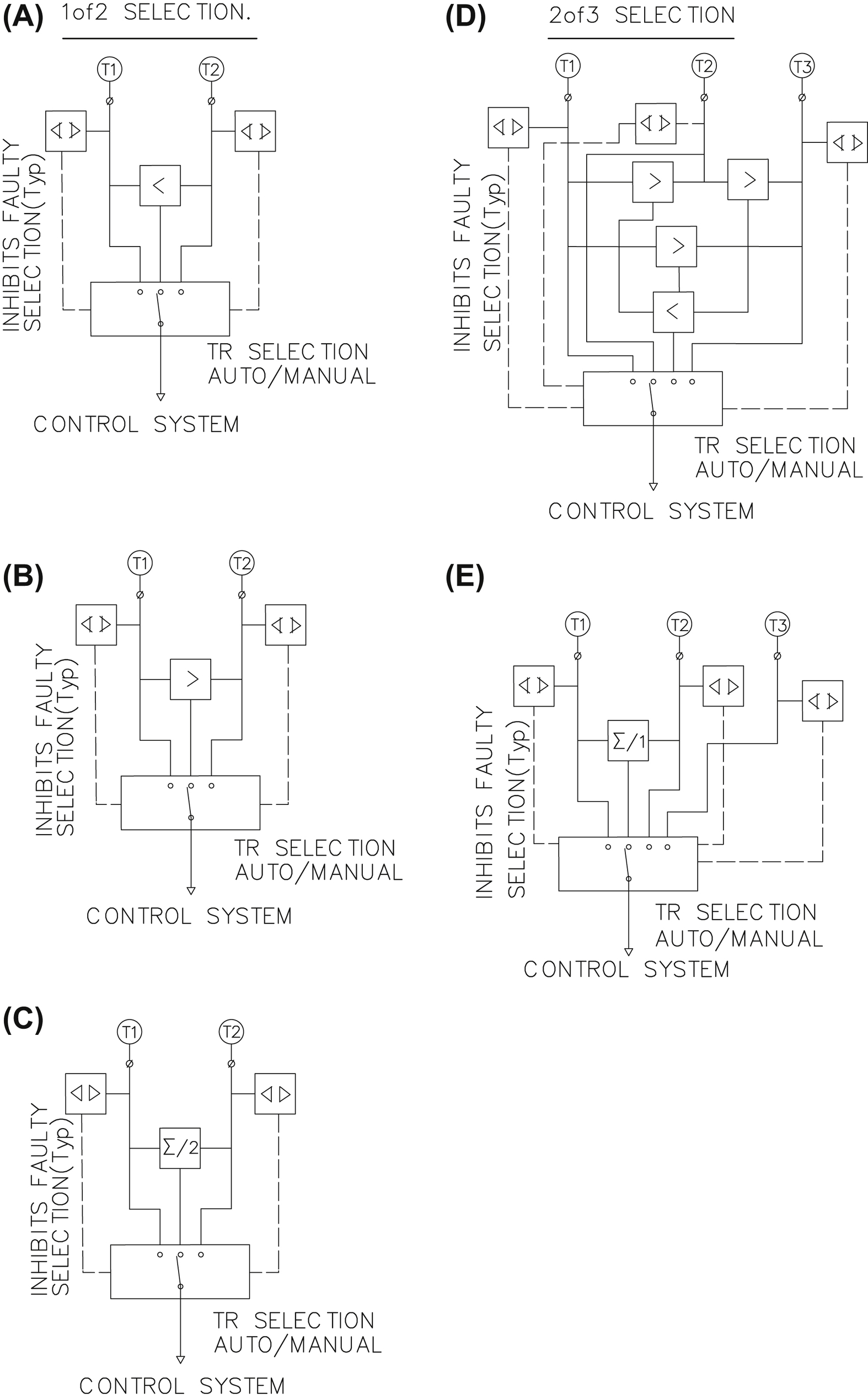
Figure XI/1.3.1-1 Redundant instrument selection methods. (A) 1of2 selection by Lo select, (B) 1of2 selection by Hi select, (C) 1of2 selection with average, (D) 2of3 voting selection (digital also), and (E) 2of3 selection with average. TR, transmitter. From S. Basu, A.K. Debnath, Power Plant Instrumentation and Control Handbook, Elsevier, November 2014; http://store.elsevier.com/Power-Plant-Instrumentation-and-Control-Handbook/Swapan-Basu/isbn-9780128011737/. Courtesy Elsevier.
• 2oo3 selection: There are two ways this can be selected, either by average or by voting.
• Selection with average: In this mode, as shown in Fig. XI/1.3.1-1E, three transmitter signals are fed to an averaging circuit (soft average selection in the signal processing part of the DCS). The output from the average unit is taken through one selection switch. In auto mode, normally average output is selected, but if one transmitter (sensor) is detected faulty (by transmitter diagnostics or by an out-of-range detector), then it will be inhibited, so the average output will be from the other two transmitters. In manual mode, any one of the three transmitters or average output can be selected. If there is a fault in any transmitter, it will be alarmed and healthy transmitter(s) will be selected in auto mode (i.e., if output is not manually selected).
• Median Selection: In this mode, as shown in Fig. XI/1.3.1-1D, three transmitter signals are initially voted through high selection between two transmitters (soft selection in the signal processing part of the DCS). The output of these three high selections is fed to the low selection for final voting as shown. Each of the transmitters, like other systems, is checked for health. The faulty transmitter is automatically voted out. The voted transmitter is selected in auto mode. In manual mode it is possible to select any of the three transmitters or the voted transmitter, but in no case is the faulty transmitter selected. This method is applicable for process switch selections.
1.3.2. Input Redundancy Interface at Intelligent Control
From IEC 61508 Part 6, a definition of commonly used architectures in safety instrumented systems is available. The elements used in a single or multiple configuration can be either sensors or final elements—mainly for input sensors, and only a few for the final element on account of cost [4]. Typical interfaces of these with an intelligent control (DCS/PLC) system are shown in Fig. XI/1.3.2-1. The configuration may be 1oo1, which is quite vulnerable because single instrument failure will make the loop unavailable.
• Dual field devices: With dual transmitters there are three possibilities: 1oo2 (not in standard), 1oo2D, and 2oo2. The first two cases are such that if anyone gives the signal, action will be taken. “D” at the end stands for diagnostics resident mainly in the control system. 1oo2 gives higher availability of the system as if anyone is true, and action is taken, but integrity may suffer because of nuisance trip. On the contrary, in the case of the 2oo2 system, availability may suffer because action will be initiated only when both are agreeing, but system integrity will be higher on account of no nuisance trip, etc. So, with a dual field device either of availability or integrity of the system will be better catered to not both. This may be compared with 1oo2 discussed in Clause 1.3.1 also.
• Triple field devices: As discussed earlier (Clause 1.3.1) in the case of 2oo3 there are two possibilities. In the case of digital inputs, voting is done (median selection). When such voting is done three times it becomes TMR, as discussed in Fig. XI/1.1.3-1.
• Diagnostics and allied discussions: Usually, the diagnostic coverage (DC) in the BPCS is much less than in the SIS. This is more so when discrete controllers are used in the BPCS. However, in the case of integrated DCS/PLC different diagnostic capability may not be that wide. This is because DCS/PLC have enough power to accept various types of signals and compute the difference between them to detect the fault. When an inconsistency is detected, the DCS is capable of signaling the abnormal situation and can continue to run the control system uninterrupted with the correct field device(s). Smart devices also have the capability to detect faults.
• 1oo1D: The diagnostic coverage can be partly integral to the transmitter and/or external in the control system (rate of change alarms, over range alarms detecting the individual fault) [4].
• 1oo2D: This was discussed in Clause 1.3.1; hence it will not be repeated here. Normally, within the valid range, the difference between the two transmitters should be within 3% (typical value depends on measurement, e.g., for pressurized vessel level measurement, e.g., drum level); if this is exceeded, an alarm is issued to the operator. In such a case the average signal may not be acceptable. One of the possibilities could be that, the control system stays put at the last good value and control may be forced to manual by the operator with an alarm.
• 2oo3: Here also differences between transmitters are computed, as just discussed. Naturally, there will be three such differences, namely, x−y, y−z, z−x. As long as these differences are within the preset limit and/or one difference is beyond the preset limit, transmitters may be correct and the median/average may be taken, but an alarm may sound for the operator to check the reason why one difference exceeded the limit. If two differences exceed the preset limit, the value of the transmitter involved in both the excessive differences is discarded, an alarm is issued to the operator, and the average value of the remaining two is used as process value [4]. When there are three differences that exceed the preset limit, this shows that sources are unreliable. Usually, the control system stays put at the last good value and control may be forced to manual by the operator via an alarm. As indicated before, the preset value is set based on measurement types.
1.3.3. Final Element Redundancy
Final control elements: In rare instances the final control elements can be duplicated, in cases when the erosive/corrosive or sticking characteristics of the fluid could cause unacceptable downtime or in cases of critical controls (viz, boiler drum level control with control valves in medium-sized power plants). The major cases are as follows:
• 1oo1/1oo1D: In typical control loops, a single control valve is used. A valve malfunction (e.g., sticking) could be detected, with some time delay, because of a drift in process variables caused by the incorrect positioning of the trim [4]. Use of a positioner or a remote position indicator is a good solution to overcome this. However, with the use of an electropneumatic positioner it is possible to check (and correct) the valve's actual position against the required one and verify that the dynamic response of the valve has not changed over time. An intelligent electropneumatic positioner provides feedback to the DCS on valve behavior for the DCS to generate an alarm, and a loop may be transferred to manual. In the majority of control systems there could be a bypass manual inching (modulating) valve (less costly) to the control valve so that control can be maintained manually, for example, a bypass valve for the main condensate valve in a power plant. For on–off control valves, to prevent trim from sticking the diagnostic functions can occasionally command the valve to move from the current condition only shortly and slightly, performing a partial travel. Such a movement command is given based on process characteristics and these movements are monitored.
• 1oo2/1oo2D: Two control valves with diagnostic coverage are used in cold standby mode, as discussed. In certain cases, similar 1oo2 are achieved in a separate way also, for example, use of two of three fans or pumps with speed controls as in cases of induced draft (ID) fans and boiler feed pumps (BFPs). In such cases, in case of failure of the final control element, say a hydraulic coupling scoop tube, a standby fan/pump with a scoop control is started. In such cases the scoop (speed) control of the standby follows the running fan/pump scoop position. Diagnostics referred to earlier help to switch from main to standby. On account of criticality of application, dosing pumps (in large boiler plants) used to have a cold standby.
1.4. Fault Tolerant Network
Based on the application, there are variations of type of computer or computing system needed. Spacecraft controls must have long-life, maintenance-free computers. Typically, an application calls for computers to operate correctly without maintenance for 5–10 years. On the other hand, applications such as aircraft, mass transportation systems, and nuclear power plants demand computers for which an error or delay can prove to be catastrophic. In these cases TMR processors and duplicated memories, etc. can be used. So far various requirements for computing systems, control systems, and field instruments have been discussed. But what about communication fault tolerance? In modern control systems where controls are highly distributed, communication between the nodes is becoming a critical part of the system architecture. In this clause a short discussion on this and on network fault tolerance will be covered. In certain cases a diverse redundancy scheme is employed, for example, redundant media (copper cable and fiber optic cable) are employed for highway communication, but this is effective only if they are routed through two different paths. This will prevent not only electromagnetic interference but also cables being cut. Media redundancy is an important issue.
1.4.1. Media Redundancy
Media redundancy is the formation of a backup path when part of the network is unavailable. IEEE 802.1D Spanning Tree Protocol (STP) supports redundant configurations of any type such as meshes, rings, or a combination of these and thereby avoids looping problems in Ethernet connections. However, it has one major limitation: lower convergence speed (30–40 s). When fast fault recovery is necessary this is not suitable. Another standard, IEEE 802.1w Rapid Spanning Tree Protocol (RSTP), has been created for faster recovery time (1 s) from topology changes. RSTP provides faster recovery by monitoring link status of each port and then generating a topology change after a link status change. RSTP also improves recovery time by adding a new port designation, which is used as a backup to the root port.
1.4.2. Network Node Redundancy
Another aspect is the failure of electronics. Switches are used for critical devices to set dual network paths. To keep the system running when a network fails, critical devices support two Ethernet interfaces to connect to both redundant switches.
1.4.3. Communication Diagnostics
There shall be diagnostic information available in the device about network communication status, node communication status, and diagnostic information for the single node concerned.
1.4.4. Fault Tolerant Ethernet
Fault tolerant ethernet (FTE) is quite a good solution. This has been developed by Honeywell. The FTE connects a group of nodes typically associated with communication paths between them, so the network can tolerate all single faults and many multiple faults. FTE can rapidly detect faults and, in case of communication failure, the switchover time is around 1 s. FTE uses commercial off-the-shelf (COTS) equipment but with increased system availability.
Table XI/1.4.4-1
Comparison Between Dual Ethernet and Fault Tolerant Ethernet (FTE)
| Connectivity | Supporting Figure Reference | Dual Ethernet | FTE |
| Number of networks | Fig. XI/1.4.4-1A | 2 | 1 |
| Dual connected nodes (DCNs) to DCN | Fig. XI/1.4.4-1Ba | 2 | 4 |
| DCN to single connected nodes (SCN) | Fig. XI/1.4.4-1Da | 1 | 2 |
| SCN to SCN in same tree | Similar to Fig. XI/1.4.4-1C | 1 | 1 |
| SCN to SCN in different tree | Fig. XI/1.4.4-1Ca | 0 | 1 |
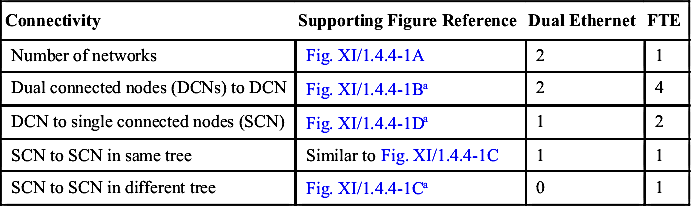
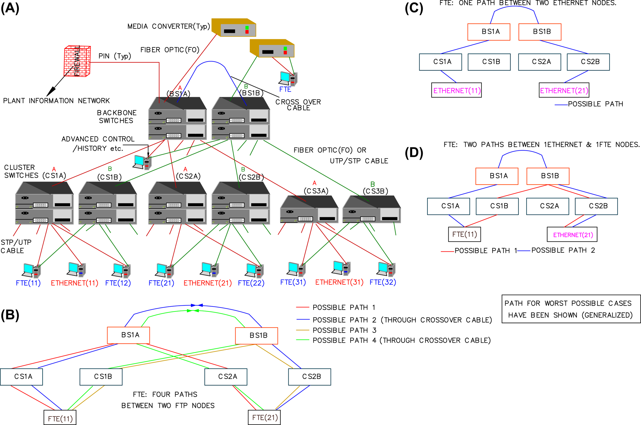
Figure XI/1.4.4-1 Fault tolerant Ethernet network. (A) Fault tolerant Ethernet network, (B) FTE network communication; FTE to FTE node communication; four possible communication paths, (C) FTE network communication; common between 2 Ethernet nodes; single possible communication path, (D) FTE network communication; common between FTE & Ethernet nodes; two possible communication path. FTE, fault tolerant Ethernet; UTP/STP, unshielded twisted pair/spanning tree protocol. The drawing is based on FTE network of honeywell (Courtesy: Honeywell); (A and B) From S. Basu, A.K. Debnath, Power Plant Instrumentation and Control Handbook, Elsevier, November 2014; http://store.elsevier.com/Power-Plant-Instrumentation-and-Control-Handbook/Swapan-Basu/isbn-9780128011737/. Courtesy Elsevier.
• Some benefits (author's book [2] courtesy Elsevier):
• Rapid response: In conventional Ethernet, there are two separate networks with each node (server) connected to both networks. The switchover time, in case of communication failure, is 30 s. FTE employs a single network and does not require a server, so changeover time is less.
• Possible communication path: FTE provides more communication path possibilities than the dual Ethernet networks, as is clear from Table XI/1.4.4-1.
• Full redundancy in a single network: A conventional Ethernet network with redundancy usually has two independent Ethernets, and naturally there will be a difference in performance and configuration between the two. However, in an FTE single Ethernet there is no such problem and at the same time it provides multipath capabilities in its unique topology.
• Network topology: A typical network topology based on Honeywell (courtesy Honeywell), FTE is shown in Fig. XI/1.4.4-1 [2]. Two parallel trees of switches and cabling “A” and “B” are linked at the top to form one fault tolerant network. Each FTE node has two ports that connect to a switch in each tree. In contrast, Ethernet nodes can connect to either if the switches are A or B. There may be one or more levels of switches and there can be multiple pairs of switches in each level. These have been designated as “cluster” and “backbone” switches in Fig. XI/1.4.4-1A. FTE to FTE communication paths and possible connections are shown in Fig. XI/1.4.4-1B–D. These are self-explanatory. However, for further detail the book [2] may be referred to. Having gathered some knowledge on fault tolerance, its time to focus on IPL and operator actions, from control systems point of view in next clause.
The discussion on fault tolerance is now concluded.
2.0. Protection Layers
A Center for Chemical Process Safety (CCPS) publication gives the following definition: “An IPL is a device, system or action which is capable of preventing a scenario from proceeding to its undesired consequence independent of the initiating event or the action of any other layer of protection associated with the scenario. The effectiveness and independence of an IPL must be auditable” [12]. Discussions on layer of protection analysis (LOPA) were covered in Chapter V, so they are not repeated here. However, a few characteristic features of protection layers are presented. Similar to fault tolerance and security, this is also important so that the control system is always safe. As per IEC 61511 standard the core idea for integrated safety and security is “defense-in-depth” with independent layers of protection to reduce process risk. The strategy behind this is that the BPCS, critical alarms, operator actions, SIS, fire and gas (F&G) systems, and any other system intended to reduce risk in the processes are capable of acting independently from each other. The major reasons for the basic requirement are to avoid common cause faults, minimize systematic errors, and provide security against unintentional access. The nature of all layers of protection is not the same. Some of them may be preventive in nature such as emergency shutdown (ESD); some may be mitigating in nature, for example, F&G(!) (which mitigates after it has happened). Other layers may be deterring in nature.
2.1. IPL Characteristics
In Clause 4.0.2 of Chapter V, the necessary characteristics of independent protection layers (IPLs) were discussed. Definitions are given here again to elaborate further an understanding of the importance of assigning IPLs. The following are major issues:
2.1.1. Specificity
An IPL is designed solely to prevent or to mitigate the consequences of one potentially hazardous event (IEC 61511-3:2003). Multiple causes may lead to the same hazardous event; the action of one IPL is necessary.
2.1.2. Independence
The performance of a protection layer is not degraded or affected by the initiating event nor is it influenced by the failure of other protection layers. This is mainly for common cause error.
2.1.3. Functionality
The protection layer must be responsive to the targeted hazardous event, meaning that it is applicable for the event so that the concerned protection layer operates in response to a hazardous event.
2.1.4. Integrity
This function is related to risk reduction, which can be reasonably expected of the protection layer in question with suitable design and management.
2.1.5. Dependability (/Reliability)
This is the probability that a protection layer will operate accurately toward the intended event under stated conditions for a specified time period.
2.1.6. Auditability
The IPL must be designed to permit validation of function and probability of failure on demand (PFD) (including drill for human error), in a regular periodic manner, that is, the ability to inspect information, documents, procedures, etc. to demonstrate the adequacy of protection and adherence to the requirements.
2.1.7. Access Security
This encompasses administrative and physical controls to prevent unauthorized access for making any change.
2.1.8. Management of Change
This is the formal prior process of reviewing, documenting, and approving any modification proposals before implementation.
2.2. Impact and PFD Guidelines
A few guidelines put forward by CCPS are summarized here:
2.2.1. Initiating Event Validation
All initiating events and IPLs should be properly maintained and validated to provide current initiating event frequency and PFD for an initiating event and IPL, respectively.
2.2.2. Human Error
Human error and other systemic errors found during maintenance and testing and restoration need to be considered in assigning the PFD (especially for IPLs with a PFD < 0.1). This is particularly important for process safety valves with block valves.
2.2.3. Human Failure During Fabrication
Human failure during fabrication of equipment can affect the failure rate of the equipment. This is important for sensitive equipment like pressure vessels from alloy.
2.2.4. Advanced LOPA
Advanced LOPA or LOPA integrated with quantitative risk analysis requires a greater degree of expertise, knowledge, and judgment. The major issues here are:
• Evaluation of common mode failure in LOPA
• Use of multiple failures in a BPCS in LOPA
• High demand rate for IPLs
• Complex mitigating controls in LOPA
• Human reliability analysis
2.3. Protection Layer Effectiveness
In line with the requirements of IEC 61511-3:2003 the standard protection layers are shown in Fig. XI/2.3-1.
The effectiveness of each of these layers is quantified in terms of PFD, that is, the probability that the IPL will fail to perform a specified function on demand. IEC 61511-3:2003 specifies typical PFDs expected from different protection layers. Typical values are indicated in Table XI/2.3-1.

Table XI/2.3-1
Typical Protection Layer Probability of Failures on Demand (PFDs)
| Protection Layer | PFD |
| Control loop | 1 × 10⁻¹ |
| Human performance (trained, no stress) | 1 × 10⁻² to 1 × 10⁻⁴ |
| Human performance (under stress) | 0.5–1.0 |
| Operator response to alarm | 1 × 10⁻¹ |
| Vessel pressure rating above maximum challenge from internal and external pressure sources | 10−4 or better when vessel integrity is maintained |
As indicated in the table the IPL is quantified by PFD of the layers, so if there are n independent layers, then the mitigated consequence frequency is given by:
![]() (XI/2.3-1)
(XI/2.3-1)
where, fi is the frequency of the initiating cause; PFDn is the probability of failure on demand of the nth independent protection layer; and fc is the mitigated frequency of the consequence. The main condition is that each protection layer is independent.
2.4. Operator Action: Protection Layer and Risk Reduction
From Clause 2.2 it is seen that operator action plays an important role both in protection layer and in risk reduction. Hence this has direct influence on PFD and therefore SIL. In this clause this will be briefly discussed.
2.4.1. Operator Action in Protection Layers
From the discussions in Chapter II it is clear that in any facility risk is a function of the frequency of a hazardous event, and the severity or consequence of the event. Also, depending on the facility function, location, design, hazardous materials, etc. and the risk tolerance limit, each facility sets its risk criteria function. From IEC 61511-3:2003 a generalized protection layer is presented in Fig. XI/2.3-1. Here it is clear that there are three active protection layers where there is scope of operator action in response to process parameters that exceed safety limits. The first is in the BPCS for the alarm system (independently considered in BPCS). The second is when the operator action is an integral part of an SIS both in preventing and mitigating an event. The third place is emergency response of the plant. This is not shown so explicitly, but it is known that the operator activates a facility emergency response system for evacuation, that is, action is mainly to initiate an evacuation process. In either the first or second case an operator may respond to an alarm/indication in the control room and initiate an action. The distinctive part in the second case is that the SIS has a PFD associated with it so operator action may alter it and thereby change the credit to the particular SIS layer.
2.4.2. Operator Action in BPCS
In BPCS, operator actions in response to process conditions are not part of a safety system (see IEC 61511 -1:2003 Clause 9.4.2) if risk reduction is less than 10. It is needless to say that BPCS should be designed as per ISA standard for alarm systems. Also the design of a BPCS operator interface should incorporate human factors engineering principles to ensure adequate response of the operator to displays and alarms. It is extremely important that operator response during both normal and abnormal conditions in the facility should not unduly violate process safety limits and norms and put the facility in an unsafe or undesirable mode or condition.
2.4.3. Operator Action in SIS
As per IEC 61511-3:2003 Clause 9.4.3, operator action as part of safety instrument functions (SIFs) can be credited with a level of risk reduction greater than 10 when the system from the sensor to the final element can be designed and evaluated as an SIS per the requirements of IEC 61511. A typical automated SIS, popularly known as an “industrial automation and control system (IACS),” from the sensor to the final element can be conceived, as shown in Fig. VIII/1.4-1 or Fig. VII/1.3-1 where the main constituents are sensor, logic solver, and final element. When an operator action such as through the display/alarm is necessary this needs to be as shown in Fig. XI/2.4.3-1.
The key point here is to recognize the additional factors that affect the PFD. The two main factors that affect the SIL of SIS with operator action are human errors and support system reliability. Human error essentially is the failure of the operator to respond correctly to the alarm/display and to take the corrective action(s) necessary to return the process/facility to a safe state. As already discussed in previous chapters in connection with alarms, the human response can be broken down into four functions:
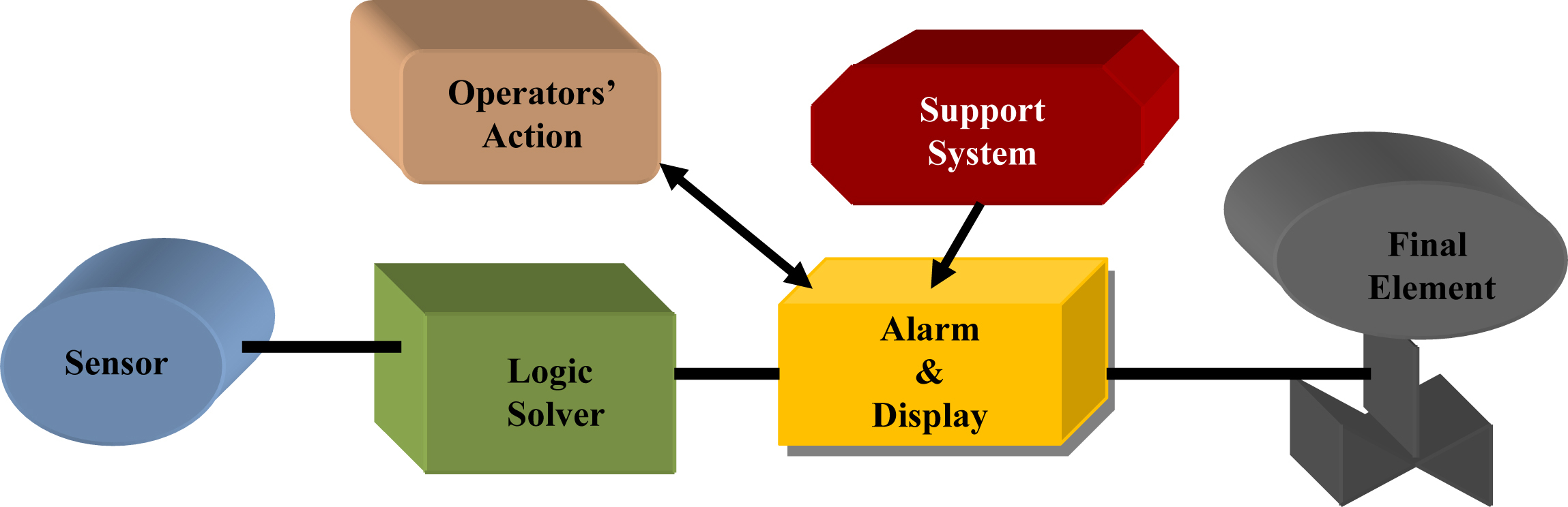
• Identification and recognition of unsafe condition
• Proper analysis of the condition
• Initiation of the required safety action
• Observation of the response of the process to the safety function
There are a number of methods for evaluation of the probability of human error, for example, the technique for human error rate prediction, discussed earlier (Clause 6.2.1 of Chapter V). The best source for determining the human error rate would be company/facility-specific historical data, but in most organizations this is not available [11]. So, other means need to be explored. The reliability of support systems necessary for an operator's action is also an important issue that can influence risk reduction. The majority of SIS systems are designed as deenergize to actuate. The calculation of PFD for these SIS systems does not generally have to take into consideration any system outside of the SIS. See also Clause 3.2.2.
With this discussion on protection layers now concluded we will now look into network security. IACS, discussed earlier, has security problems for which there are specific standards such as IEC 62443. In subsequent clauses issues related to security in networking will be discussed briefly. This is especially important for integrated network systems. However, prior to looking at security issues it is important to understand why segregation between BPCS and SIS has been discussed in IEC standards. In the following clause the discussions have been presented on segregation between BPCS and SIS from an architectural point of view, so that the discussions on security issues pertinent to networks will be meaningful.
3.0. BPCS and SIS Integration: Architectural Issues
From a commercial and economic point of view the majority of IACS manufacturers and system integrators are developing systems with integration of both BPCS and SIS. Such demands are so high they could hardly be ignored. In Clause 2.2 of Chapter VII some aspects were already discussed. Here the discussions will be on architecture of the integrated systems: due consideration will be given to IEC standards. It is advisable that Clause 7.4.2.3 of IEC 61508-2:2010 and Clause 11.2.2/11.2.3/11.2.4/11.2.9/11.2.10 of IEC 61511-1:2004 are referred to.
3.1. Major Issues Behind Separate Systems
Following are the main reasons as per IEC 61511 [15]:
3.1.1. Impact
Impact on SIS because of common cause and mode and systematic failure of BPCS
3.1.2. Flexibility
Retention of flexibility of changes, maintenance, testing, and documentation for BPCS
3.3.3. Facilitation
Facilitation of functional safety assessment and validation of SIS
3.1.4. Analysis Time
Analysis time reduction to ensure requirements for safety
3.1.5. Supports
Support for access security and enhancement of cyber security for SIS so that revisions in BPCS do not affect SIS
3.2. BPCS and SIS Architectures
The following are several ways the two systems can be conceived.
Completely separate (air gap): BPCS and SIS are completely separate with no physical connections between them, for example, PLC-based BPCS and hardware SIS.
Interfaced: Two separate systems with a link, for example, RS 232 and MODBUS. This may be for data exchange for display/monitoring.
Integrated: Separate BPCS and SIS (separate sensor, logic solver, and final element) but connected through a common network. Here there may be chances of commonality of hardware/software; hence a CCF issue! On the contrary, if there are different suppliers, the chances of CCF systematic failure may be less. Further integration is possible when there is a common engineering station or separate I/Os but fallback of BPCS and SIS controller. In these cases, obviously the suppliers may be the same; hence the chances of CCF, etc. will be higher but with the use of different technology the issue may be circumvented.
It is seen from the foregoing that as the standards were developed for completely separate BPCS and SIS, naturally not only is third party certification necessary but many considerations must be taken into account at all stages so that the main philosophy behind the standards is not diluted. Again it is also a fact that most of the systems available in the market are integrated systems.
3.2.1. Integration Approach
Right from the planning stage due consideration must be given to integrating BPCS and SIS. A few relevant points in this regard shall include but not be limited to the following:
• Adherence to duty holder philosophy at all stages such as specification, design, engineering verification validation, etc. separately for BPCS and SIS
• Evidence of confidence of all stakeholders (see IEC 61511) or suppliers and duty holders
• Adherence to local and international regulations including IEC
• Compliance with IEC 61508-1:2010 and 61511-1:2004 for functional safety management
It is known that in SIS, separate IPLs are to be considered. Therefore it is necessary that such independence must be demonstrated properly. Also if there are any credits to be claimed for BPCS, then Clause 9.4.3 of IEC 61511-1:2003 should be followed (see Chapter VI).
3.2.2. Integration Guidelines
There have been separate guidelines for this and these must be followed [16]. The following are the major issues to be addressed and documented:
• Training and culture
• Competence
• Safety and security
• Location
• Access control
• Manufacturer's guidelines
• Procedure
• Human interface
• Separation
• Segregation
• Redundancy
• Diversity
3.2.3. Salient Issues
In view of the foregoing, some relevant and important issues need to be considered for integrated BPCS and SIS and shall include but not be limited to:
• Diversity in hardware and software between BPCS and SIS to avoid CCF, etc. So, it is necessary to address these explicitly and they should be certified by a third party.
• IEC 61511 must be followed for validation and functional safety assessment and documentation for SIS.
• Electrical and logical separation of processing units between two systems

• Specific and separate development, engineering and systematic capability in line with the standards for SIS
• Separate SIS zone and use of a firewall to combat risk from cyber security in an integrated system. IEC 61511and 62443 standards need to be followed.
• Use of the black channel technique as per IEEE design for communication (Fig. XI/3.2.3-1)
The subject of integration of BPCS and SIS is now concluded and we can move on to issues related to security in SIS.
4.0. Security Issues in SIS
Security issue is one of the most important aspects in the current design of SIS. With the help of an open interface like Open Platform Communications (OPCs) (Fig. XI/4.0-1) it is possible to integrate not only BPCS and SIS but the entire enterprise network. Common and open communications protocol architecture standards are replacing the diverse and disparate proprietary systems of industrial control systems. This migration empowers users to access new and more efficient methods of communication as well as more robust data, quicker time to market, and interoperability. Integrated systems developed by system integrators offer communications and security solutions that are flexible enough to collaborate with a variety of third party DCSs and easy enough to deploy. However, all these advantages are coupled with new cyber-related vulnerabilities and risks. “Open-based standards have made it easier for the industry to integrate various diverse systems together, it has also increased the risks of less technical personnel gaining access and control of these industrial networks”(courtesy National Communication Systems Bulletin). Some of the issues could be: use a denial of service (DoS) shutdown, delete system file (downtime), modify logging (data loss), and plant a Trojan and gain control [2]. In a modern SIS, which is a digital system and often connected to a network, there is a real concern that a targeted cyber attack can disable or affect its performance. Cyber security is increasingly critical for maintaining control and safety integrity and for ensuring both communications security and integrity. Security risks are increased in the case of a totally integrated system. SIS demand integrator skills significantly more advanced than those required for the usual PLC project. Most safety systems need to have their communications functions integrated into the PLC/DCS communications infrastructure safely and securely.

Figure XI/4.0-1 OPC open interface. From S. Basu, A.K. Debnath, Power Plant Instrumentation and Control Handbook, Elsevier, November 2014; http://store.elsevier.com/Power-Plant-Instrumentation-and-Control-Handbook/Swapan-Basu/isbn-9780128011737/. Courtesy Elsevier.
As stated there are open standards, for example, OPC, that make it possible for integrators to work with a standard protocol that gives them greater flexibility and economy but with the probability of higher risks because of security. Another important issue is that SIS functions are partitioned appropriately from the PLC/DCS functions so that a loss of communications or integrity will not prevent the SIS from performing its function, and keep the system in a safe state. Now it is time to look at the issues closely.
4.1. Security Issues: General Discussions
According to M. Barzilay of ISACA: “Cyber security is the sum of efforts invested in addressing cyber risk…” From an ISA point of view, security issue refers to the prevention of illegal or unwanted penetration, intentional or unintentional interference with the proper and intended operation, or inappropriate access to confidential information in industrial automation and control systems [17]. Cyber security therefore is mainly concerned with protection against unauthorized access (intentional or unintentional) to save data and information systems from theft or damage to prevent the system from any disruption of operation and unwanted functioning of the system. IEC/ISA 62443 (formerly ISA 99) is the relevant standard. Many propose to treat cyber risks as physical risks, that is, to check and assess vulnerability, frequency of occurrence, consequences, etc.
4.1.1. Vulnerability Check
Vulnerability check is a very important assessment. Vulnerability assessment requires checks at entry points, architecture, and current protective measures. Introduction of information technology (IT) components into industrial controls further complicates the situation. Deployment of wireless and remote control technologies coupled with trends to integrate the process system into the business networks opens the gates for cyber attacks. The usefulness of such technologies cannot be undermind. Therefore the balance between security and operational functionality needs to be maintained with a clear mission to detect vulnerability at the earliest possible opportunity so that it can be treated accordingly to prevent the system from serious damage.
• Major causes of cyber attacks: Vulnerability of business networks from cyber attacks make people more concerned about cyber security. Major causes that make the systems vulnerable for cyber attacks may be as follows:
• High dependency on automation in secured external network connections and lack of qualified cyber security business in industrial controls
• Trends for moving toward COTS operating systems and designs to integrate BPCS, SIS, and business networking and access through standard open system protocols
• Adaption of open protocols such as internet protocol to access IACS, that is, common protocol vulnerability
• Use of joint venture, alliance with other partners, meaning number of organizations accessing the same network parts—database attack
• Added complexity of disgruntled staff, amateur attackers, criminals and terrorists, and availability of automated tools to access networks
• Upward trend of malicious code attacks on business networks year by year to collect information in a dishonest way and attacks through the backdoor or a hole in the network perimeter and/or man-in-the-middle or insecure coding
• Chances of attack through field devices
• Other types of attacks such as communication hijack
• Major effects of cyber attacks: A few major effects of cyber attacks shall include but not be limited to the following:
• DoS:Network flooded with spurious data, denying access to legitimate users
• Penetration: Gaining control to disrupt the network, develop backdoor entry, and steal confidential information, for example, imported tools, viruses, etc.
• Social engineering: System can be vulnerable if a member of staff unsuspectingly divulges sensitive information [18]. Attacker entry through legitimate user.
4.1.2. Probable Checklist to Prevent Cyber Attacks
The following is a typical checklist:
• Secure components (locking if necessary) so that settings cannot be changed easily
• Implement and use robust passwords for hardware and software
• Check vulnerabilities of “smart” devices and secure them as far as possible
• Check vulnerability of wireless transmission and secure using proper encryptions
• Disable unused ports, file transfer protocol (FTP) connections as far as possible, and minimize keep-alive and other settings that hold a disconnected port open; also reassess site strategy for security situations and measures taken [18]
• As far as possible disable USB and related common connections
• Use hardware and software firewalls and antimalware protection
• Create a site-specific strategy for software (especially open software) updates
• Create multilayer access points for information and enforce login/logout. Some use constantly changing numbers (generated in small dongles given to authorized persons) to be added after the desired password
• Report any employee leaving an organization who has had access to a dongle or anyone who loses a dongle for the generation of arbitrary numbers; access must be disabled immediately by IT staff
• Implement a change management policy to control access and track changes to configurations and programs [18]
• Implement recovery by only authorized persons with backup files
• Train all staff regarding the dangers of cyber attacks and social engineering impacts
4.1.3. Architectural Aspects
In modern transmission control protocol (TCP)/IP-based computing environments, implement a single integrated corporate network for the business that drives operations in a control system. The main concern of IACS as part of larger conjoined architectures is providing security procedures that cover the control system domain as well. Unique vendor-specific protocols and inherent legacy system security may not be adequate to protect mission-critical systems against modern cyber attacks [19]. Because there are several key differences between traditional IT environments and control system environments, it will be unwise to simply applying IT security technologies into a control system. Major differences are given in Table XI/4.1.3-1.
Also the requirements of three basic parameters such as availability, confidentiality, and integrity have different priorities, namely, for control systems like SIS the order of priority will be: integrity, availability, and confidentiality, whereas in the case of IT, confidentiality will be of the highest priority.
“Homeland Security Defense in Depth” [19] gives good guidelines for divisions in zones, etc. The salient features are:
• To implement multiple layers of defenses
• Entire integrated network to be divided into functional zone and interconnections made between them, for example, in offshore mud handling, pipe handling, etc. process control zones may be divided into area zone, for example, low-pressure mud handling, high-pressure mud handling/choke kill section, etc. as per requirements of the facility.
• Rules of data exchange between zones through conduits
• Deployment of firewalls for hardware and software (better to choose from different vendors)
• All external data or access to be routed through DMZ to act as buffer
For a better understanding the foregoing is depicted in Fig. XI/4.1.3-1. In the figure demilitarized zone (DMZ) is a buffer between external traffic and a trusted internal network. There is no direct connection conduit between external traffic and internal network. DMZ acts as a buffer to permit allowable data exchange between external system and internal network without a direct conduit.
Table XI/4.1.3-1
Differences in Security Handling in Information Technology (IT) and Industrial Automation and Control Systems (IACSs) [19]
| Security Issue | IT | IACS |
| Antivirus mobile code | Easy to implement and update | Impact on control system difficult to implement |
| Time criticality | Delay may be allowed | No delay—real time |
| Security awareness | Moderate | Not much developed except physical means |
| Patch management | Easily defined and automatic | Original equipment manufacturer-specific (long time to manage) |
| Technology support | 2–3 years multivendor | 10–20 years one vendor |
| Test and audit | Easy modern method | Modern method not suitable |
| Change management | Regular scheduling | Strategic scheduling for impact on control system |
| Incident response | Easily developed and deployed | Uncommon beyond system resumption activities |
| Physical and environmental security | Poor to excellent | Excellent, but remote places may be unmanned |
| Security system development | Integral part of system development | Not an integral part of development |
| Compliance | Limited regulatory | Specific regulatory |
4.1.4. Major Cyber Attacks
The following are major issues related to cyber attacks:
• Backdoor and network perimeter hole: “Backdoor” is used to gain unauthorized, but not necessarily physical, access. A single point of compromise in an integrated network may provide extended access because of preexisting trust established among interconnected resources. Often the security perimeter of a control system is compromised for better connectivity without precautions being taken. In wireless communications, the residual effects of default installations and attackers, once having discovered wireless communications points, can use this situation to their advantage. Significant service-based vulnerabilities in the 802.15.4 protocol could lead to jamming and DoS [19]. Modern architecture with remote accesses for controls has the security perimeter relocated to the remote access making the system vulnerable. To allow robust information to be provided via external services, such as a web or FTP server, communication must be made from the web server to the internal databases or historians, and this connection is made via the firewall.

Figure XI/4.1.3-1 Zones and levels with firewall and demilitarized zone (DMZ) in an integrated network. FE, final element; HMI, human–machine interface; MIS, management information system; PU, processing unit.
• Common protocol attacks: Although a wide variety of security implications and vulnerabilities have been identified with OPC services and standards, OPC standards and application programming interfaces are common in control system environments. OPC vulnerabilities could be simple system enumeration and password vulnerability or they could be more complex like remote registry tampering and buffer overflow flaws, etc. These could result in threats to IACS. The installation of undetected malware, DoS attacks, escalated privileges on a host, and/or even the accidental shutdown of IACS are vulnerabilities for which solutions are available but these are not always very successful.
• Field devices: Remote accessed field devices and IT compatible instruments are quite vulnerable. For remote access, to provide for the collection of operational and maintenance data, some modern equipment has embedded file servers and web servers to facilitate robust communications [19]. In a trusted network this issue is not that serious but for an integrated network this could be dangerous. In addition to a dedicated communication channel, engineers often use publicly accessible telephone networks or dedicated lines for modem access. When left unsecured, an attacker can connect remotely with little effort, and the remote connection may be difficult to detect. Again field devices are part of an internal and trusted domain, so access to these devices can provide an attacker with access to the control systems. Attackers often add these field devices to their list of targets. If a device is compromised, an attacker can leverage control over the device and cause unauthorized actions without being easily recognized.
• Man-in-the-middle attack: Control system environments with air gapping exchanges are often less secured. Major issues in this type of attack are:
• The ability for an attacker to reroute data
• The ability to capture, stop the system functioning, and analyze critical traffic
• The ability to reverse engineer control protocols to gain control over communications
Address resolution protocol (ARP) helps to maintain routing. Poisoning (manipulation) of the ARP tables is the key to this attack. With ARP table poisoning, an attacker can force system traffic to be rerouted through the computer the attacker has compromised, as shown in Fig. XI/4.1.4-1.
• Structured query language (SQL) data injection: IT databases are maintained by SQL. In an integrated network of IT and IACS, an attacker may use this to gain control of data from IACS by exploiting the communication channel (between the enterprise network and the control network) and disregarding the protection mechanism of IACS.
• Insecure coding: Some industrial control systems have very old custom-built or unsupported (by vendor) programming code. The programming code can suffer from insecurities such as:
• Control environments have been built with no security training.

Many control system codes do not have any authentication or encryption to avoid slow response caused by code encryption. As a result the systems become insecure.
• Improper procedure: On account of large network integration and remote access there has been wide use of modems within the industrial control system environment. When modems are improperly managed from a security perspective, and they are always left on without any type of authentication, there is every possibility of a cyber attack. Even with a detailed procedure to access through a remote capability, many control system devices have poor logging capabilities and have not been properly turned on for auditing purposes. In such cases, guidelines in standards like NERC-CIP 002-009 and NIST SP 800-53 may be helpful for reference.
There are many other types of cyber attacks such as database attack or data injection, etc.
4.1.5. Cyber Attack Defense Mechanisms
Cyber security is not just the application of specific technologies to combat risks. From Aberdeen Research in November 2011 (Ismail, 2011) it can be inferred that the best-in-class companies must establish a formalized risk management strategy and ingrain safety as part of the culture. In a similar way, effective security programs for an organization depend on the willingness of the company to accept security as a constant constraint on all cyber activities. Accordingly, the necessary strategic framework involving personnel, operational philosophy is to be developed. This will help to acquire in-depth knowledge of security programs so that they can be handled effectively to the overall gain of the company. Major issues are:
• Know the security risks that an organization faces
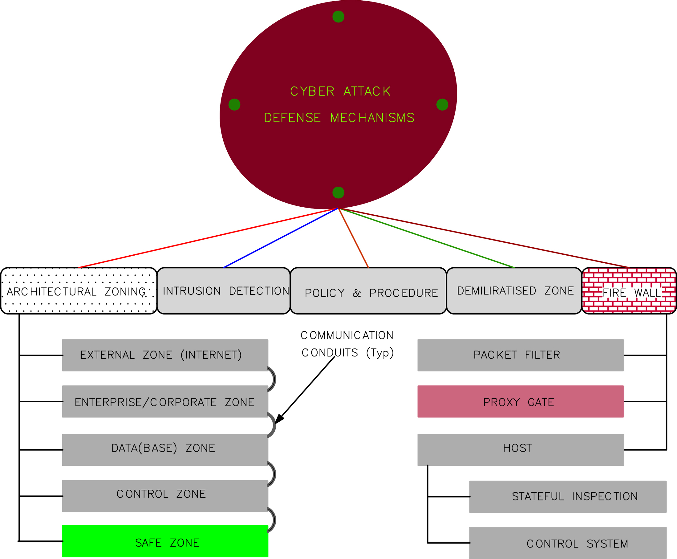
• Use resources suitable to mitigate the risks
• Follow existing or emerging security standards at different phases as applicable
• Create and customize specific controls most suitable for the organization
As shown in Fig. XI/4.1.5-1 there are five major defense mechanisms to combat cyber attack:
• Architectural zone (conduit)
• Intrusion detection
• Miscellaneous policies and procedures
• DMZ
• Firewall
• Architectural zones: It is important to understand how the entire integrated network is connected and how it could be segmented. Based on functional relationships and data flow, large integrated enterprise/corporate networks including control systems can be divided into five basic zones:
• Corporate zone: This is the business area such as email servers, domain name servers (DNS), etc. On account of connectivity (Fig. XI/4.1.3-1) to the external zone it has a lot of risks and less priority (however, much higher than the external zone).
• Data(base) zone: The majority of monitoring and control takes place in this zone. It is a critical area for continuity and management of a control network. Operational support and engineering management systems are located in this zone. Naturally, huge data handling is involved with the help of data acquisition servers and historians. This zone is in the middle of corporate zone and control zone. Since there is a direct connection with the corporate zone it is a DMZ with firewalls on either side, as shown in Fig. XI/4.1.3-1.
• Control zone: This is the area of connectivity to control systems such as controllers (PLCs), human–machine interfaces (HMIs), and basic I/O devices such as actuators and sensors. Basically, there are three sections shown, namely, a management information system for plant management (which at times shares data with the database zone as discussed earlier), a main process control (namely, closed/open loop control system and data monitoring), and an applicable area control (e.g., choke kill control in offshore drilling, or offsite control like a coal handling plant in a power station). All I/Os are connected to this zone either by hardware directly or by a fieldbus system. This zone has very high priority and firewalls like a control firewall may be deployed. Additional external firewalls may also be used.
• Safe zone: This usually has the highest priority because these devices have the ability to automatically control the safety level of an end device such as SIS. Typically, the risk is lower in this zone because these devices are only connected to the end devices.
• Commonly used tools: The following are the major tools that could be used to segment the integrated network, keeping control environment and SIS in mind:
• Firewalls (single, multihomed, dual, cascading)
• Routers with access control lists
• Configured switches
• Static routes and routing tables
• Dedicated communications media
• Intrusion detection: Intrusion detection is a type of security management system for networks. The system gathers and analyzes information from various areas within a computer or a network to identify possible security breaches. There could be two types of breaches: intrusions (outside) and misuse (within the organization). Intrusion detection uses vulnerability assessment (also referred to as scanning), which is a technology developed to assess the security of a network. Intrusion detection is a comprehensive set of tools and processes providing network monitoring that can give an administrator a complete picture of how the network is being used. Implementing a variety of these tools helps to create a defense-in-depth architecture that can be more effective in identifying attacker activities, and using them in a manner that can be preventive. Each organization must assess its particular situation, identify the criticality of the impacted devices, and develop a prioritized course of action. Unfortunately, a simple and prescriptive remedy applicable for all situations does not exist.
• Policy and procedure: A well-documented and detailed policy and procedure that is specific to the industrial control systems environment is essential to combat cyber attacks. Regular periodic review and maintaining policies and procedures will be very useful.
• Security policy: Just incorporating the security policy of the IT sector in IACS will not do. Control system security must be practical and enforceable, and it must be possible to comply with the policy. The policy should not have an adverse effect on productivity and cost. It should be well supported and could be better developed by involving personnel from management and system administrator during policy development.
• Log and event management: Commonly used security incident event management technologies can be deployed for centralized log and event management. Central security data consoles give security personnel a complete view of security tools, for example, ID system logs, firewall logs, and other logs that can be generated from any number of devices.
• Security training: Security training and robust security awareness programs that are specific to the IACS domain are critical to the security of industrial control systems as well as the safety of those involved with any automated processes.
• Patch management: This is common in the IT sector. A good patch management plan and procedure is also required in the IACS environment to create a layer of defense against published vulnerabilities.
• Incident response and forensics: In the event a security-related incident in the control system domain, activities to recognize, respond, mitigate, and resume need to be established. An incident response procedure will instruct employees on the steps to take if a computer on the network has been compromised.
• DMZ: DMZ stands for demilitarized zone; actually it is a demarcation zone. As discussed earlier in Clause 4.1.3, DMZ is created as a buffer between external zones and trusted internal zones by isolating the host. This does not allow a direct conduit between the two. Multiple DMZs are created for separate functionalities and access privileges. Usually, in a good network all connections to IACS LAN are routed through the firewall. Multiple DMZs have proved to be very effective in protecting large integrated architectures. Network administrators need to keep an accurate network diagram of their system and its connections to other protected subnets, DMZs, and the outside. As is seen in Figs. XI/4.1.3-1 and XI/4.4-2, enterprise/business servers having access from outside have DMZs through firewalls. Basically, a DMZ is the outward facing level of an application. It is a subnetwork that resides between a known/trusted internal network and an external network, providing services to the outside without allowing direct access. The following are some system components of a DMZ [2]:
• Public-facing server
• Public-facing FTP server
• Email gateway
• Public-facing DNS
• Traffic management and security server
• Streaming video, etc.
• Firewall: Firewalls provide additional levels of defense. Types and functional aspects of firewalls are extremely important for IACS. This is discussed separately in the next clause.
4.1.6. Operational Issues
Once the defense mechanisms are set it is necessary to implement and maintain them. A few common points regarding these are elaborated here:
• Use a strong password as protection
• Restrict physical and electrical access to a needs-only basis. Also restrict access to subcontractors, etc.
• Implement separate and distinct authentication mechanisms, especially for control system access
• Form a security team with trained security personnel
• Revoke access for dismissed or resigned employees
• Enforce a consciousness program for employees on security issues so that they keep access through a public line for long periods (even it is left open after a short duration, new authentication may be required, if the application allows this)
A firewall is an important defense and demands separate discussions.
4.2. Firewall
A firewall protects a computer network from unauthorized access. Firewalls may be hardware, software, or a combination of both. The first firewall in an external and internal trusted network is a proxy server acting intermediately by receiving and selectively blocking data at the boundary. It also helps in hiding the LAN addresses from outside (to avoid ARP poisoning) [2]. Functional details of a firewall are presented in Fig. XI/4.2-1.
4.2.1. Category and Classification of a Firewall
Depending on the hardware/software, firewalls can be categorized and the classifications are based on function.
• Category: There are three categories of firewall, namely, hardware firewall, software firewall, and a combination of the two. Advantages and disadvantages of hardware and software firewalls are enumerated in Table XI/4.2.1-1.
• Classification of firewalls: Apart from being categorized as hardware/software or a combination of both, the broad classification of firewalls is depicted in Fig. XI/4.1.5-1. Based on TCP/IP layers, firewalls are classified as network layer firewall, application layer firewall, etc. For control systems, firewalls are as follows:

Figure XI/4.2-1 Firewall functional details. (A) Firewall used as Packet filter, (B) firewall as circuit level relay, (C) firewall as application gateway, and (D) multi layer firewall structure. DMZ, demilitarized zone. From S. Basu, A.K. Debnath, Power Plant Instrumentation and Control Handbook, Elsevier, November 2014; http://store.elsevier.com/Power-Plant-Instrumentation-and-Control-Handbook/Swapan-Basu/isbn-9780128011737/. Courtesy Elsevier.
Table XI/4.2.1-1
Hardware Versus Software Firewall [2]
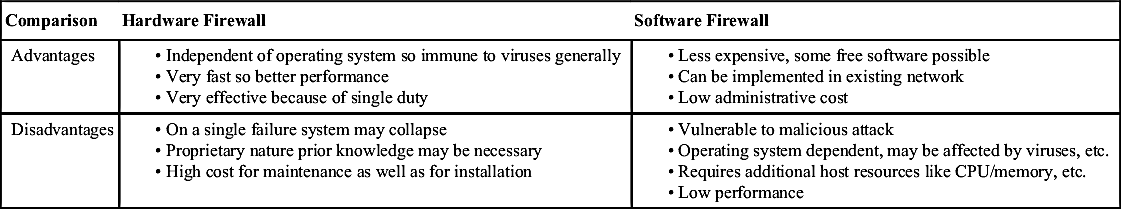
• Packet filtering firewall
• Proxy server firewall
• Host firewall
Short description of each of them has been presented in next clause.
4.2.2. Short Discussions on Various Firewalls
• Packet filtering firewall: These look after and analyze the packets going out and coming in to allow or deny access based on certain rules. Types of packet filters are shown in Table XI/4.2.2-1.
Table XI/4.2.2-1
| Types | Details |
| Stateless packet | This is also known as a static IP filtering firewall. It does not remember the information about the previously passed packet. This is not a smart filter and can be fooled quickly. This type is vulnerable to user datagram protocol-type packets. It has a very high throughput but is costly. It is included with router configuration software or with most open source operating systems. It is highly vulnerable for security. |
| IP packet | IP packet filtering firewall: Every packet is handled on an individual basis. Previously forwarded packets belonging to a connection have no bearing on the filter's decision to forward or drop the packet. |
| Stateful packet | This is a pure packet filtering environment. It is known as smart firewall or dynamic-type packet firewall, because it remembers the information about previously passed packets. |
• Proxy server firewall: These firewalls are critical in hiding the networks they are protecting and are used as primary gateways to proxy the connection initiated by a protected resource. They offer more security but at the cost of speed. Here, traffic does not flow through the proxy server gateway firewall because it acts as a buffer and has a direct effect on network performance. This type of firewall is suitable to segregate business networks from control networks. A firewall proxy server essentially turns a two-party session into a four-party session, with the firewall emulating the two real hosts, as shown in Fig. XI/4.2.2-1. They filter at the application layer of the open system interconnectivity model so they are often called application layer firewalls. As a gateway they require users to direct their connection.

• Host firewalls: This software firewall protects ports and services specifically for the device on which it is installed. There are also third party software packages and these are host resident for servers, workstations, laptops, etc. There are various types of host firewalls such as control firewall and stateful inspection firewall, as shown in Fig. XI/4.1.5-1. Stateful inspection firewall filters at the network layer to determine the legitimacy of the sessions, and evaluate contents of the packets at the application layer. Control firewalls are hardware based directly on the controller to regulate traffic.
4.2.3. Firewall Functionality
The functionality of various firewalls is detailed in Table XI/4.2.3-1. The table should be seen in conjunction with Fig. XI/4.2-1.
Table XI/4.2.3-1
| Type Name | Feature |
| Packet filter (see Fig. XI/4.2-1A and D) | • First line of defense (Fig. XI/4.2-1A). • Internet and other digital network data travel in packets of limited sizes. Consists of the Data, Ack, Request or Command, Protocol Information, Source and Destination IP Address, Port Error Checking Code, etc. • Filtering consists of examining incoming and outgoing packets compared with a set of rules for allowing and disallowing transmission or acceptance. • Rather fast because it really does not check any data in the packet except IP header. Works in the network layer (internet) of the Open Systems Interconnection (OSI) model. • Fast but not foolproof. IP address can be spoofed. |
| Circuit relay/gateway (see Fig. XI/4.2-1B and D) | • One step above the packet filter and commonly known as “stateful packet Inspection” to check the legitimacy or validation of the connection between two ends (in addition to packet filtering operation) based on the following: • Source destination IP address/port number • Time of day • Protocol • Username and password • Operates on the transport layer. Stateful inspection makes the decision about connection based on the data stated above. |
| Application gateway (application proxies) (see Fig. XI/4.2-1C and D) | • Acts as proxy for the application at the application layer of the OSI. See Fig. XI/4.2.2-1 also. • Authorizes each packet for each protocol differently. • Follows specific rules and may allow some commands to a server but not others, OR limits access to certain types based on authenticated user. • Setup is quite complex; every client program needs to be set up. Also each protocol must have a proxy in it. • True proxy is much safer. |
| Table Continued | |


From S. Basu, A.K. Debnath, Power Plant Instrumentation and Control Handbook, Elsevier, November 2014; http://store.elsevier.com/Power-Plant-Instrumentation-and-Control-Handbook/Swapan-Basu/isbn-9780128011737/. Courtesy Elsevier.
4.2.4. General Discussions
A firewall policy is extremely important from a cyber security point of view. To obtain effective results it is essential that there is a well-planned policy for a firewall and its management. It should be properly maintained and periodically audited. Any weakness in policy and failure to implement the policy will result in failure of the firewall. If one is considering an IP virtual private network (VPN) one needs to consider the placement of the VPN with respect to the firewall. The following are some of the guidelines for a firewall policy:
• Internal and external access and their extent
• Remote user access
• Virus protection and avoidance
• Encryption requirement if any and permitted
• Program usage
With this the discussions on firewalls are concluded. Next we will explore the standards regarding cyber security, especially for SIS.
4.3. Cyber Security Standards
From the discussions in Clause 4.1 it is quite clear that there are many holes or vulnerabilities in cyber security. Such vulnerabilities come in various forms such as improper authentication, improper input validation, etc. The percentage share of each of them varies. To appreciate the percentage share of each category of such vulnerabilities, Fig. XI/4.3-1 may be referred to. This is based on ICS-CERT vulnerability disclosure [20].
Since most of the control systems are intelligent and there is a clear tendency to opt for integrated systems with COTS and open system protocol, the vulnerability of the network from cyber attack is always in the positive gradient of growth. Also those with malicious intentions will always try to access the network. So, all these have accelerated the rate of attacks. Naturally, some countermeasures to save the business are necessary. Initially, ISA 99 standards, created by the International Society for Automation (ISA), were released as the American National Standards Institute (ANSI) documents. These were the original standards for cyber security in IACS. Later, in 2010, to align these standards with the international standards organization International Electrotechnical Commission (IEC), the standards were renumbered and IEC 62443 emerged. Generally, IEC and ISA standards are functionally identical. These standards cater for the end user, system integrators, product manufacturers, etc. The standard is numbered IEC 62443-x-y; where x stands for categories 1, 2, 3, and 4. Each category has divisions (indicated by y), for example, category 1 has four divisions— ISA/IEC 62443-1-1/2/3/4. Similarly, other categories are: ISA/IEC 62443-2-1/2/3/4; ISA/IEC 62443-3-1/2/3; ISA/IEC 62443-4-1/2. These are further elaborated as follows.

4.3.1. Categories and Divisions in Standards
There are four general categories:
• Category 1: General: This has four divisions mainly concerned with general things like concepts, models, and terminology. Also included are security metrics and security life cycles for IACS.
• Category 2: Policy and procedure: This has four divisions, and coverage includes various aspects of creating and maintaining an effective IACS security program. Targets mainly the asset owner.
• Category 3: System: This has three divisions. This category mainly focuses on security technology, risk assessment, and security requirements including zone conduit concepts.
• Category 4: Components: This has two divisions. These include work products that describe the specific product development and technical requirements of control system products. This is primarily intended for control product vendors, but can be used by integrators and asset owners.
Table XI/4.3.2-1
62443 Series Standards (Standard Number IEC/ISA 62433-x-y)
| IEC | ISA | 62443-x-y | Title | Status |
| IEC/TS | ISA | 62443-1-1 | Terminology, concepts and models | P, UR |
| IEC/TR | ISA/TR | 62443-1-2 | Master glossary of terms and abbreviations | D |
| IEC | ISA | 62443-1-3 | System security compliance metrics | D |
| IEC/TR | ISA/TR | 62443-1-4 | IACS security life cycle and use case | PL |
| IEC | ISA | 62443-2-1 | IACS security management system requirements | P, UR |
| IEC | ISA | 62443-2-2 | IACS security management system implementation guidance | PL |
| IEC/TR | ISA/TR | 62443-2-3 | Patch management in the IACS environment | P |
| IEC | ISA | 62443-2-4 | Requirements for IACS solution suppliers | P |
| IEC/TR | ISA/TR | 62443-3-1 | Security technologies for IACS | P, UR |
| IEC | ISA | 62443-3-2 | Security assurance levels for zones and conduits | V |
| IEC | ISA | 62443-3-3 | System security requirements and security assurance levels | P |
| IEC | ISA | 62443-4-1 | Product development requirements | V |
| IEC | ISA/TR | 62443-4-4 | Technical security requirements for IACS components | V |

4.3.2. ISA/IEC 62443 Series Standards and Technical Reports
It is clear from the foregoing that ISA/IEC 62443 is series of standards not a single standard. Some of them have been published and some are in development stages, etc. See http://isa99.isa.org for the latest status. The title and status of these are elaborated in Table XI/4.3.2-1.
4.3.3. Objective and a Few Definitions of Terms
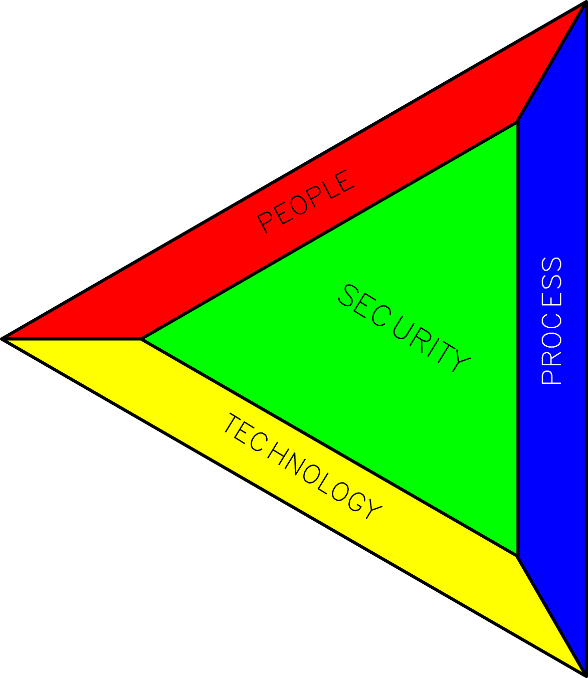
Figure XI/4.3.3-1 Security element groups. Developed based on draft ISA 62443-1-1. Courtesy: ISA.99.
Table XI/4.3.3-1
Connection Between Various Elements (Based on ISA 62443-1-1)
| Element | Connections |
| People | Role: Asset owner/operator, system integrator, product supplier, service provider, compliance authority. |
| People | Beyond the scope of the standard but are connected to security indirectly: Resourcing, relationship, intent, support decision, awareness. |
| Process | Security policy, organization of security, asset management, human resource security, physical and environmental security, access control, communication/operation/business management, incident management, system acquisition, and maintenance management. |
| Technology | Use control, system integrity, data confidentiality, restriction of data flow, response to event in time, availability of resource. |
• Objective and mission of the standard: It is needless to state that critical requirements of IACS are to ensure that the system should never have the potential to cause impacts to essential services and functions, including emergency procedures. This is quite different from the requirements for IT security, which puts more emphasis on information—integrity, availability, and confidentiality. Accordingly, the mission for the standard will be to develop a set of well-engineered specifications and processes for the testing, validation, and certification of IACS products. Standards are to be developed so that uniform methods and rules will be developed to reduce the time, cost, and risk of developing, acquiring, and deploying control systems. Such a standard is developed by establishing a collaborative industry-based program among asset owners, suppliers, and other stakeholders.
• Security elements: According to the standard, three elements, namely, people, technology, and process, constitute the security standard, as shown in Fig. XI/4.3.3-1.
Security connections between these elements are listed in Table XI/4.3.3-1.
• Security level: Assets that make up the system under consideration shall be assigned a security level in accordance with standard ISA 62443-2-2.
• The security life cycle: The life cycle is focused on the security level of the system over time. A change in asset will trigger changes in security level or a change of vulnerability or an asset may trigger changes in a physical asset. There are a few basic steps for the security development life cycle assessment (SDLA), which are detailed in Clause 4.3.5.
• Zone and conduit: This is a process of segmenting or dividing a system under consideration for the purpose of assigning a security level and associated measures; it is an essential step in the development of the program.
• Security maturity program: A security maturity program integrates all aspects of cyber security incorporating desktop and business computing systems with IACS. The development program shall recognize that there are steps and milestones in achieving this maturity. Security maturity phases are shown in Table XI/4.3.3-2.
• Defense-in-depth: In a complex system it is impossible to achieve the security objective with a single countermeasure. In such cases, superior approaches involving application of multiple countermeasures in a layered or stepwise manner are used, for example, firewall and intrusion detection.
4.3.4. Conformity Assessment as Per IEC
There are two kinds of violations: casual or coincidental violation and intentional violation. Therefore conformity requirements call for protection against:
• Casual or coincidental violation
• Intentional violation using:
• Low resources, generic skill, and low motivation
• Advanced ways to moderate resources, motivating IACS-specific skills
• Higher resources and motivation coupled with IACS-specific skills
4.3.5. Security Development Life Cycle Assessment
The basic steps as per IEC activity for SDLA are as follows [21]:
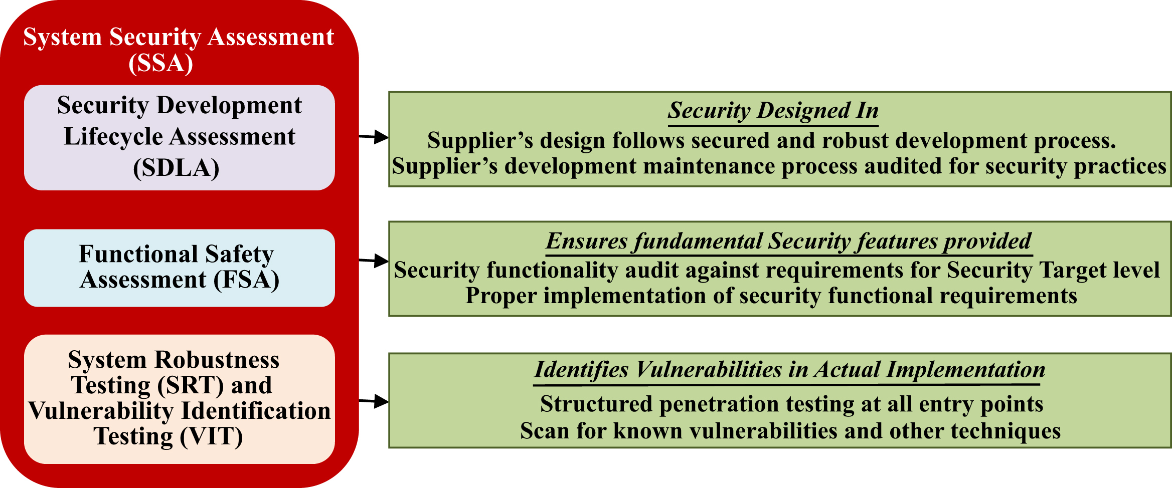
• Security management process
• Security requirements specification
• Security architecture design
• Security risk assessment (threat model)
• Detailed software design
• Document security guidelines
• Module implementation and verification
• Security integration testing
• Security process verification
• Security response planning
• Security validation testing
• Security response execution
4.3.6. System Security Assessment
The major issues involved in conformity assessment are:
• The system has been designed and developed as per a robust security process and norms.
• Supplier's design and maintenance process has been thoroughly audited to ensure robust security practices as per stipulation in the standard.
• Each system has a target security level, so it is necessary to audit security functionality of the system against the stipulated requirements.
• Systems have been audited for proper implementation of all security requirements.
• Vulnerability of the implemented system has been identified:
• Structured penetration testing at all entry points
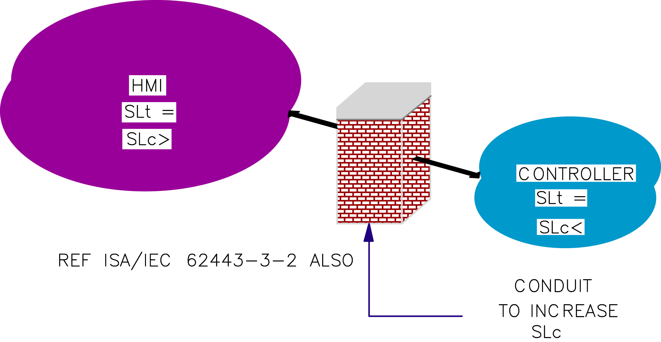
The system security assessment program as per the foregoing details is depicted in Fig. XI/4.3.6-1. It is worth noting that in many places, many parts of IEC/ISA 62443 have been mentioned as standard, while in reality these may be only in draft form. One may refer to http://isa99.isa.org for the latest status.
This partially concludes the discussion on the IEC/ISA standard for cyber security. We now move on to the separate and specific issues of zone and conduit, which are quite important in the context of SIS security, especially when the architecture is a large integrated network.
4.4. Zone and Conduit Concept
Earlier it was shown that there is a difference in the requirements of security in IT and control systems. The security level is not uniform in a network especially when it is complex, large, integrated, and includes an enterprise network. Discussions on zones and conduits are mainly in line with the international standard discussed in the previous clause. To understand the zone conduit concept Fig. XI/4.4-1 may be referred to, in conjunction with Clause 4.4.3. Prior to starting discussions, a short explanation on the relevant terms is presented:
• Zone: Difference in security level at various parts of the network can be addressed by dividing the network into zones, defined as logical and physical informational, physical and application assets. To get an idea, Fig. XI/4.4-2 may be referred to. In fact, Fig. XI/4.1.3-1 also has zone division in a similar manner. One point worth noting is that SIS in both cases is segregated from the process control system via firewall protection so that it is in a safe condition and in a safe zone. In fact, this is a zone within a zone acting as a safety layer and an example of defense-in-depth. There can be multiple zones and separate zones.
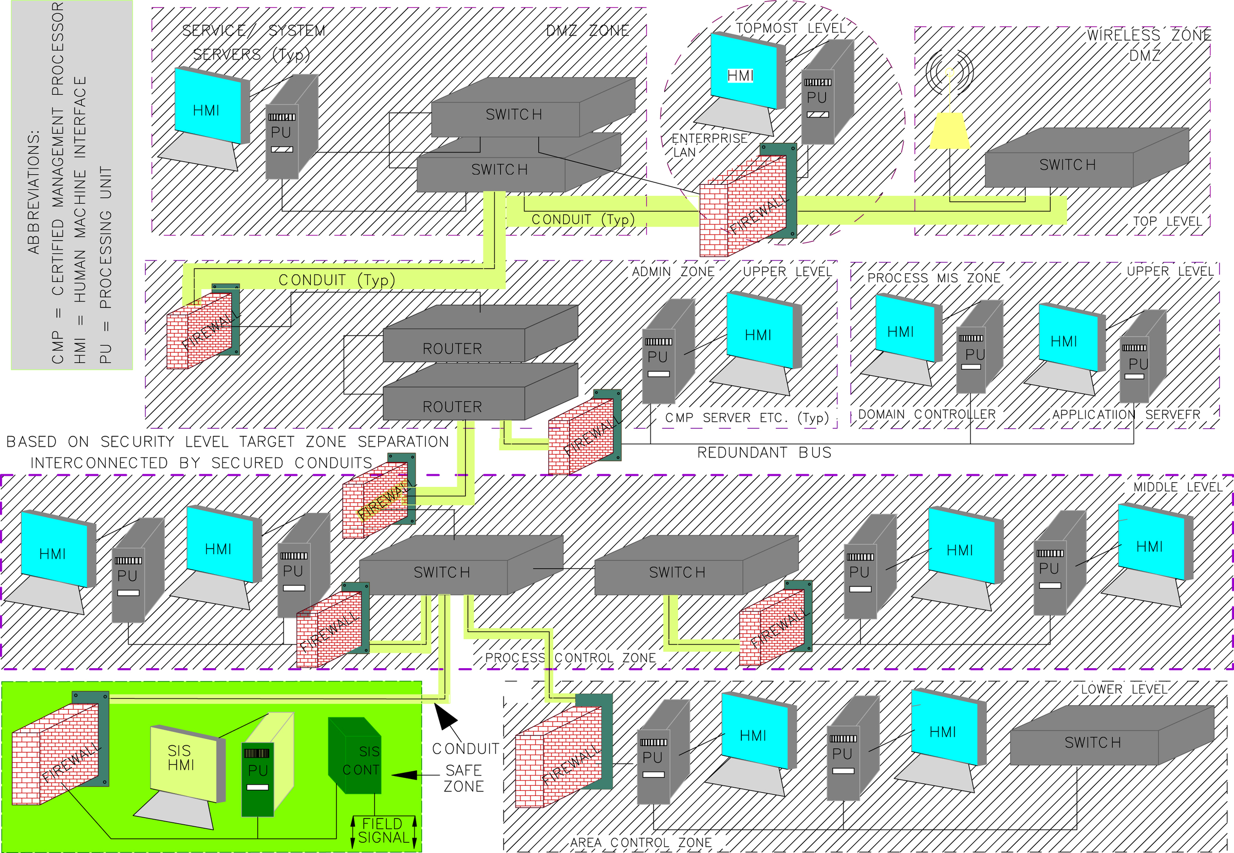
• Conduit: In a network, information flows in and out or within zones. For secured communication, ISA/IEC 62443 series standard defines a special type of security zone communication as a communication conduit. Conduit types are:
• Single–single Ethernet
• Multiple data carrier, multiple network cables, or direct physical access
• Trusted: Never crosses the zone boundary—if it does, then it must be secured at both ends
• Untrusted: Conduits are not at the same security level at the zone end points
Conduits can connect different zones or various entities within a zone.
• Channel: Channels possess the security properties of conduits and are used as communication media within the conduit. Like a conduit, a channel can be trusted or untrusted. Trusted channels allow communication between security zones or may extend the virtual zone to the entity outside the physical security zone. Untrusted channels are the communication path to another zone having a different security level.
• Security requirement: Before going for zone structure, one first need assess the security goal/requirements, then to place the asset in zone of the zone structure of the network. A group of assets within a security border should have a link to communicate with the outside zone. Such a link may be physical movement and/or electronic communications. Electronic communications may be two kinds: remote access and local communication:
• Remote access: This takes place when the entity is not in close proximity and mainly refers to out-of-zone communication.
• Local communication: This refers to communication between entities within a zone. Assets within the borders are protected to give the same security level.
• Reference model: Reference model refers to the framework for understanding the relationship among the entities for a particular (network) environment and it is helpful for development of standards and specifications to support the environment. The major constituents are:
• Governance
• Risk program
• Vulnerability management
• Awareness and training
• Identity access management
• Information and knowledge management
• Document control
• Monitoring and reporting
• Internal and external audit
4.4.1. Discussions on Zone
There are a few issues that need to be addressed:
• Definition explanation: Zone is an important tool for security program success. Therefore it is important for zone to be correctly defined. For this, a reference model architecture and asset model must be used to develop the security zone and security level for achieving the security goal. When a device is to cater for different security levels, then it is better to create a separate zone blending various zones or mapping devices for more stringent requirements. A historian, which is needed to connect to both management information system and control system, is an example of such a device. For these kinds of devices, a suitable logical boundary can be created. Only those with privilege to that level and application can access them.
Table XI/4.4.1-1
| Characteristic Issue | Related Issues |
| Security attributes | Zone: Scope and risk; security: Level, target, strategy and policy; permitted activity and communication |
| Asset inventory | Hardware: External, computer, and development; Access: Authentication and authorization; spares, monitoring and control; simulation, training and reference manual |
| Access | Access and control requirements of the zone |
| Threat and vulnerability | Identification and evaluation of vulnerability for risk assessment and necessary documentation. Suggestion of suitable countermeasure for vulnerabilities in the zone |
| Consequence: Security breach | As a part of risk assessment the consequences shall be analyzed to suggest necessary countermeasures |
| Authorized technology | IACS technologies are evolving to meet the business requirements in better and more efficient ways, but there are a number of vulnerabilities. Naturally, proper selection is important to minimize security vulnerability along with an efficient system to meet the challenges |
| Change management | Formal process to maintain the accuracy of the zone and how to change the security policy to meet the security goal without any compromise |
• Zone characteristics: Zone characteristics as per the standard draft are shown in Table XI/4.4.1-1.
4.4.2. Conduit Details
The following are important issues related to conduits:
• Definition explanation: Conduits are used for protection of communication assets, that is, applicable for communication processes. Conduits are responsible for physical and logical grouping of communication assets. As the name suggests it protects the security of channels comprising physical connection data, etc. Like a pipe it connects various zones and assets. In IACS, conduits are like network elements such as switches, routers, etc. Conduits can group two dissimilar network technologies. Conduits analyze communication threats and vulnerabilities.
• Characteristics: Conduit characteristics are enumerated in Table XI/4.4.2-1.
4.4.3. Security Level
There is some similarity and commonality between safety and security. Safety integrity is represented in terms of SIL. Similarly, security is represented in terms of security level. However, security systems have a large set of consequences and circumstances, which lead to a large number of events. Initially, when sufficient data are not available, security level is measured qualitatively like low/medium/high for the purpose of comparison within an organization. However, in the long term, it is necessary to adopt a quantitative approach using mathematical equations. Basically, security level is a quantitative representation of various security zones that need to be developed with security targets in mind. There are three types of security level: security level target (SL-T), security level capability (SL-C), and security level achieved (SL-A).
Table XI/4.4.2-1
| Characteristic Issue | Related Issues |
| Security attributes | Conduit: Scope and risk; security: Level, target, strategy and policy; permitted channels; documentation |
| Asset inventory | Similar to zone; accurate lists of communication channels |
| Access | Access to limited sets of entities and access and control requirements |
| Threat and vulnerability | Identification and evaluation of vulnerability for risk assessment of assets within conduits that fail to meet business requirements; necessary documentation. Suggestion of suitable countermeasure for vulnerabilities in the zone |
| Consequence: Security breach | As a part of risk assessment the consequences shall be analyzed to suggest necessary countermeasures |
| Authorized technology | IACS technologies are evolving to meet the business requirements in better and more efficient ways, but there are a number of vulnerabilities to conduits. Naturally, proper selection is important to minimize security vulnerability to conduits along with an efficient system to meet the challenges |
| Change management | Formal process to maintain the accuracy of the conduit's policy and how to change the security policy to meet the security goal without any compromise |
| Connected zones | Description in terms of the zone to which it is connected |
• SL-T: This defines the desired level of security of a particular system—each security zone and/or entire system comprising security zones. This is normally determined only after performing risk assessment of the system and ascertaining a particular level of security.
• SL-C: This is the security level that components/systems can provide when properly implemented. This shows the capability of the component/system without the use of additional compensating device(s).
• SL-A: This represents the actual level of security of a particular system. This is measured with available data, when the system design is complete, or the system is in place to establish that the security level target is achieved.
4.4.4. Integrated Network With Zones and Conduits
Having some idea of the various relevant terms it is time to apply these to the network normally encountered in IACS. Fig. XI/4.4-1 is a good example to show how zones and conduits are helpful in meeting the same security level target with different security level capabilities.
HMI designed with a standard Windows-based operating system may have inherent higher security level capability than that achievable in a standard controller. Now, if both systems are set to have the same security level target in the network, then additional device(s) may be necessary to bring the controller security level capability to the same available in HMI. This is a very costly proposition; instead conduits may be applied that effectively can increase the security level capability of a controller and bring both to the same security level. In Clause 4.1.3 the necessity for zone divisions was discussed and is shown in Fig. XI/4.1.3-1. Now, similar network conduits are shown in Fig. XI/4.4-2.
In this architecture, starting from the enterprise top level, various levels are shown. Such level differentiations are mainly based on functional use of information. Here it is worth noting that both IT and IACS levels are shown. The topmost level may be connected to the internet (not shown here). As is seen, different zones have been created. It is worth noting that each has different functions, which demand different security levels and also different communication devices such as switches and routers as shown. Top-level wireless zones and service zones have been connected with the help of a firewall and separate conduits. Admin zone and process control MIS zone have separate security zones with different security targets. Here it is worth noting that an application processor (related with historian discussed in Clause 4.4.1) is a device that is connected to both process control system and process MIS with the help of a conduit to be connected to two separate security zones. Also switches and routers are used to maintain such a connection. Area controls are basically an extension of process control. These may have the same or separate security zone and security level targets with different vendors/networks, namely, choke and kill or cementing controls are examples of area controls. So, these are shown separately. SIS controls, for example, SIS, F&G, ESD, always demand separate treatment and have different security zone and security level targets. SIS has been shown separately and connected via a different conduit to cater to different security level targets. It is better to focus on the connections of SIS and BPCS and MIS parts. Also there could be other variations regarding configurations for SIS and BPCS integration, as elaborated later and as shown in Fig. XI/4.4.4-1 [22]. This is to be seen in conjunction with Fig. XI/4.4-2.
• SIS controllers and HMIs in the same bus of BPCS as shown in Fig. XI/4.4.4-1A. In such configurations there is a high probability of DoS attack on account of both network flood or malicious traffic and open bus malware attacks.
• In another configuration as shown in Fig. XI/4.4.4-1B, HMI of SIS may be on the same bus with SIS controllers in a separate bus with peer-to-peer communication. The controller communicates with HMI via an interface module. Here SIS controllers may be susceptible to fewer DoS attacks because the interface between SIS controllers and HMI will have a similar attack as discussed in the first case.

Figure XI/4.4.4-1 Basic plant control system (BPCS) and safety instrumentation system (SIS) integration in a common bus. (A) Open bus integration, (B) common bus integration. HMI, human–machine interface; LAN, local area network; MIS, management information system; PU, processing unit. Developed based idea from Z.D. Tudor, Cyber Security Implications of SIS Integration with Control Networks; The LOGIIC SIS Project; ISA automation week; https://logiic.automationfederation.org/public/Shared%20Documents/LOGIIC%20SIS%20AW11%20Final%20PPT.pdf.
• The third configuration is when there is a separate bus as shown in Fig. XI/4.4-2; the chances of cyber attack may be much less, but it is also an integrated system. The same may be achieved without real integration, by a simple RS link with Modbus protocol also for data polling.
It is worth noting that SIS may exchange information with a process control system but may not use the same data bus to ensure separate security level capability economically. With this, the discussions on zone conduit are concluded. We will now look into other possibilities to conclude the discussions on security issues.
4.5. Discussions on Security
There are a few other means to meet the security requirements of a network. OPC is one such choice. In many systems there are OPC servers and clients for security analysis. Access to an OPC server is restricted to the persons with higher level privilege, whereas OPC client is allowed to others. Some SIS systems also self-police communications access. In one case, Invensys Operations Management (www.iom.invensys.com) collaborated with Byres Security (www.tofinosecurity.com), a cyber security firm, to add an OPC firewall to its Tricon Communications Modules (TCM). The firewall enabled a layer of defense-in-depth that lets systems integrators enjoy the flexibility and integration benefit of OPC Classic without worrying about security systems that have in the past been associated with distributed component object model (DCOM)-based systems. According to Byres Security “A reliable OPC firewall means that in addition to blocking hackers and viruses from accessing the safety system, integrators can deliver dynamic port management and built-in traffic-rate controls to prevent many basic network problems from spreading throughout a plant.” Trinity Systems, UK developed a remote viewer that takes advantage of the communications security features of the Triconex TCM and Triconex Firewall. The viewer allows the end user to have a simple window into the SIS from the business or primary control network. The Firewall and the Communication Module's on-board User Access Security Model ensures that it is a read-only window that can never impact the safety functionality. This combination of OPC-based accessibility with true defense-in-depth security provides cost-effective and secure access. Joe Scalia, portfolio architect, Invensys Operations Management, said “An OPC firewall mitigates those risks by managing the traffic to and from the communications module, providing further assurance that a cyber incursion will not compromise integrated communications between the safety and critical control systems and supervisory HMI or distributed control systems.” Implementing the HMI portions of a safety system is critical to securing communications between the SIS and the DCS. Communications integrity, including cyber security, must be ensured so that safety-based actions such as reads from the HMI to the safety system can be executed securely and without interruption. The new module from MTL Instruments and Byres Security is said to provide a safe and secure means of locating what is on control system networks. The new module from Tofino listens for traffic and then uses special characterization techniques to determine the types of control devices on the network. When it discovers a new device, it prompts the system administrator to either accept its deductions and insert the new device into the network inventory diagram, or flag the device as a potential intruder. This way, an up-to-the-minute network map is always available to the control engineer. The module also guides the user while creating appropriate firewall rules to allow or block messages, based on what it has learned about the network traffic. Technical complexities such as IP addressing and TCP/UDP port numbers are managed behind the scenes, making firewall configuration easier for a controls professional.
As an example, Yokogawa Electric Corporation has the ProSafe-RS safety instrumented system, which has obtained the ISASecure Embedded Device Security Assurance (EDSA) certification. The ISASecure program has been developed by the ISA Security Compliance Institute with the goal of accelerating the industry-wide improvement of cyber security for IACS. It achieves this goal by offering a common industry-recognized set of device and process requirements that drive device security, simplifying procurement for asset owners and device assurance for equipment vendors. The ISASecure EDSA certification has three elements: communication robustness testing, functional security assessment, and software development security assessment, and is based on the IEC 62443-4 standard [13–15].
With this, the discussions on cyber security are concluded with a hope that an even better development in this area would make SIS more secure and easier to handle. For further details, interested readers may consult reference books and watch out for the release of the international standard ISA/IEC 62443 series.
List of Abbreviations
| ARP | Address resolution protocol |
| BPCS | Basic plant control system |
| CCF | Common cause failure |
| CCPS | Center for chemical process safety |
| COTS | Commercial off the shelf |
| DCOM | Distributed component object model |
| DCS | Distributed control system |
| DMZ | Demilitarized zone |
| DoS | Denial of service |
| ESDA | Embedded device security assurance |
| ESD | Emergency shutdown system |
| F&G | Fire and gas |
| FTC | Fault tolerant control |
| FTE | Fault tolerant Ethernet |
| FTP | File transfer protocol |
| FTU | Fault tolerant unit |
| Table Continued | |
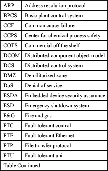
| HART | Highway addressable remote transducer |
| HMI | Human–machine interface |
| IACS | Industrial automation and control systems |
| IEC | International Electrotechnical Commission |
| I/O | Input/output |
| IP | Internet protocol |
| IPL | Independent protection layer |
| IT | Information technology |
| LOPA | Layer of protection analysis |
| MDT | Mean downtime |
| MIS | Management information system |
| MTBF | Mean time between failure |
| MTTR | Mean time to repair |
| NMR | N-modular redundancy |
| OPC | Open platform communications |
| OSI | Open systems interconnection |
| PFD | Probability of failure on demand |
| PLC | Programmable logic controller |
| SDLA | Security development life cycle assessment |
| RSTP | Rapid spanning tree protocol |
| SIF | Safety instrument functions |
| SIL | Safety integrity level |
| SIS | Safety instrumentation system/supervisory information system (in case of DCS) [16] |
| SQL | Structured query language |
| STP | Spanning tree protocol |
| TCM | Tricon communications modules |
| TCP | Transmission control protocol |
| TMR | Triple modular redundancy |
| VPN | Virtual private network |

..................Content has been hidden....................
You can't read the all page of ebook, please click here login for view all page.