
3.0. Hazardous Area Classification and Electrical Safety
3.1. Explosion Discussions
3.1.1. Explosion of Flammable Substances

Table X/3.1.1-1
Flammable Liquid Classification (US Based)
| Standards/Flash Point (Below) | OSHA | NFPA 30 | ANSI |
| Flash point <−7°C | Flammable | Class I | Extremely flammable |
| Flash point −7°C–38°C | Flammable | Class I | Flammable |
| Flash point 38°C–60°C | Combustible | Class II | Flammable |
| Flash point 60°C–66°C | Combustible | Class III | Combustible |
| Flash point 66°C–93°C | Combustible | Class III | Combustible |

Table X/3.1.1-2
Flammable Liquid Classification as per Directive 98/24/EC
| Designation of the Flammable Liquid | Flash Point and Boiling Point (°C) |
| Highly flammable | Flash point <0°C and boiling point <35°C |
| Easily flammable | Flash point <0°C and boiling point >35°C or 0°C < flash point < 21°C |
| Flammable | 21°C < flash point < 55°C |
3.1.2. Range of Explosion


3.1.3. Flammable Substances
3.1.4. Air/Oxygen
3.1.5. Sources of Ignition
3.2. Electrical Area Classification (EAC)
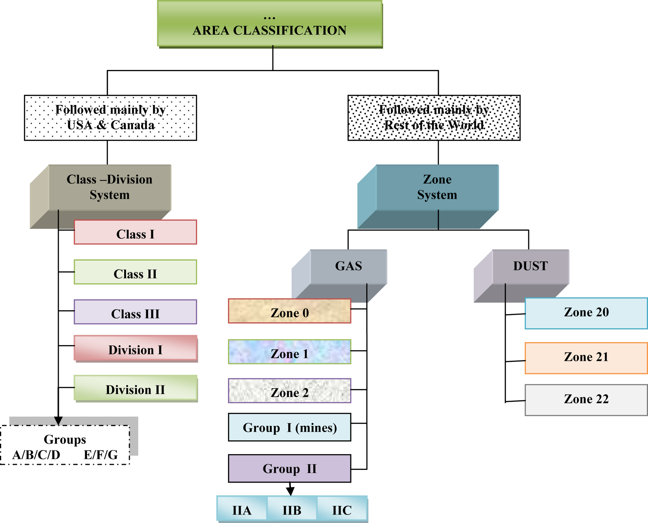
3.2.1. Class Division System
Table X/3.2.1-1
Class—General Nature of Hazardous Materials
| Class | Area |
| I | Area/location in which flammable gases or vapors1 may (or may not2) be present in sufficient quantities to produce explosive or ignitable mixtures. 1: important is gas/vapor 2: may not: qualifies as sufficient to indicate chances of explosion. |
| II | Area/location in which combustible or conductive dusts1 (in suspension intermittently, or periodic) may (or may not2) be present in sufficient quantities to produce explosive or ignitable mixtures. 1: important is combustible or conductive dusts 2: may not: qualifies as sufficient to indicate chances of explosion. |
| III | Area/location in which ignitable fibers1, not likely to be in suspension, may (or may not2) be present in sufficient quantities to produce explosive or ignitable mixtures. For this class, grouping does not have any relevance. 1: examples: wood chips, cotton, nylon, etc. 2: may not: qualifies as sufficient to indicate chances of explosion. |
Table X/3.2.1-2
Division—Likelihood of Hazardous Material Present
| Division | Presence of Hazardous Materials Present |
| I | The substance referred to by class is present continuously, intermittently, or periodically or present because of normal operation, and has high probability of producing explosive or ignitable mixtures. |
| II | The substance referred to by class is present only in abnormal conditions (such as a container failure or system breakdown) or for a short duration and has low probability of producing explosive or ignitable mixtures. |
Table X/3.2.1-3
Grouping of Hazardous Materials
| Group | Hazardous Materials | Applicable |
| A | Acetylene. | Gases/vapors Class I |
| B | Hydrogen, fuel, and combustible process gases containing more than 30% hydrogen by volume or gases of equivalent hazard such as butadiene, ethylene, oxide, propylene oxide, and acrolein. | |
| C | Cyclopropane, CO, ether, hydrogen sulfide, morpholine, ethyl ether, and ethylene or gases of equivalent hazard. | |
| D | Acetone, ammonia, benzene, butane, cyclopropane, ethanol, gasoline, hexane, methanol, methane, vinyl chloride, natural gas, naphtha, propane, or gases of equivalent hazard. | |
| E | Combustible metal dusts: aluminum, magnesium, and their commercial alloys or other combustible dusts whose particle size, abrasiveness, and conductivity present similar hazards in connection with electrical equipment. | Dusts and flying Class II |
| F | Carbonaceous dusts, carbon black, coal black, charcoal, coal/coke dusts (>8% total entrapped volatiles). | |
| G | Dusts not included in E and F such as flour dust, grain dust, flour, starch, sugar, wood, plastic, and chemicals. |

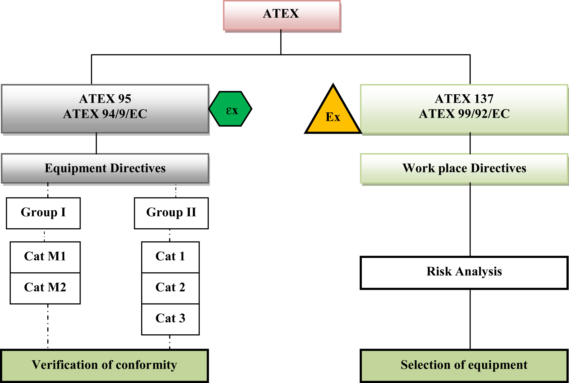
3.2.2. ATEX Directives
Table X/3.2.1-4
Surface Temperature Division and Electrical Apparatus Temperature Limit
| Temperature Code | Ignition Temperaturea in °C (°F) | Ignition Temperatureb Range in °C | Permissible Temperature Electrical Apparatus in °Cc |
| T1 | 450 (842) | >450 | 450 |
| T2 | 300 (572) | >300 to ≤450 | 300 |
| T2A | 280 (536) | ||
| T2B | 260 (500) | ||
| T2C | 230 (446) | ||
| T2D | 215 (419) | ||
| T3 | 200 (392) | >200 to ≤300 | 200 |
| T3A | 180 (356) | ||
| T3B | 165 (329) | ||
| T3C | 160 (320) | ||
| T4 | 135 (275) | >135 to ≤200 | 135 |
| T4A | 120 (248) | ||
| T5 | 100 (212) | >100 to ≤135 | 100 |
| T6 | 85 (185) | >85 to ≤100 | 85 |

Table X/3.2.2-1
Area Classification for Equipment in Explosive Atmospheres (ATEX 95)
| Group/Category | Group I: Equipment in Mines Below or Above Ground | Group II: Equipment in Other Locations, Endangered by Explosive Atmospheres |
| Category 1 | Category M1 (Cat M1) | Category 1 (Cat 1) |
| Category 2 | Category M2 (Cat M2) | Category 2 (Cat 2) |
| Category 3 | Not applicable | Category 3 (Cat 3) |

3.2.3. Zone System
Table X/3.2.3-1
Zone Classification (Gas and Dust)
| Material | Zone | Explanation |
| Gas | 0 | A location in which an explosive atmosphere consisting of a mixture with air of flammable substances in the form of gas, vapor, or mist is present continuously or for long periods or frequently. |
| Gas | 1 | A location in which an explosive atmosphere consisting of a mixture with air of flammable substances in the form of gas, vapor, or mist is likely to occur in normal operation occasionally. |
| Gas | 2 | A location in which an explosive atmosphere consisting of a mixture with air of flammable substances in the form of gas, vapor, or mist is not likely to occur in normal operation but, if it does occur, will persist for a short period only. |
| Dust | 20 | A place in which an explosive atmosphere in the form of a cloud of combustible dust in air is present continuously, or for long periods or frequently. |
| Dust | 21 | A place in which an explosive atmosphere in the form of a cloud of combustible dust in air is likely to occur in normal operation occasionally. |
| Dust | 22 | A place in which an explosive atmosphere in the form of a cloud of combustible dust in air is not likely to occur in normal operation but, if it does occur, will persist for a short period only. |

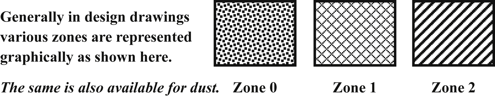
Table X/3.2.3-3
Relation Between ATEX 95,137, and IEC 60079-0
| Material Type | ATEX 137 Zone | ATEX 95 Group | IEC 60079-0 Group (Equivalent) | Equipment Category (ATEX 95) | EPL IEC 60079-0 |
| Gas/vapor | Zone 0 | II | II | 1G | Ga |
| Gas/vapor | Zone 1 | II | II | 2G, 1G | Gb, Ga |
| Gas/vapor | Zone 2 | II | II | 3G, 2G, 1G | Gc, Gb, Ga |
| Dust | Zone 20 | II | III | 1D | Da |
| Dust | Zone 21 | II | III | 2D, 1D | Db, Da |
| Dust | Zone 22 | II | III | 3D, 2D, 1D | Dc, Db, Da |
| CH4/C-dust (mine) | – | I | I | M1 | Ma |
| CH4/C-dust (mine) | – | II | II | M2, M1 | Mb, Ma |

3.3. Discussions on Miscellaneous Standards
3.3.1. Area Classification Principles/Procedures
3.3.2. Discussions on Zone Systems
3.3.3. ATEX Directives—Explanations
3.3.4. Protection Selection
Table X/3.3.4-1
| Concept | Code | Zone | Category | Principle of Protection |
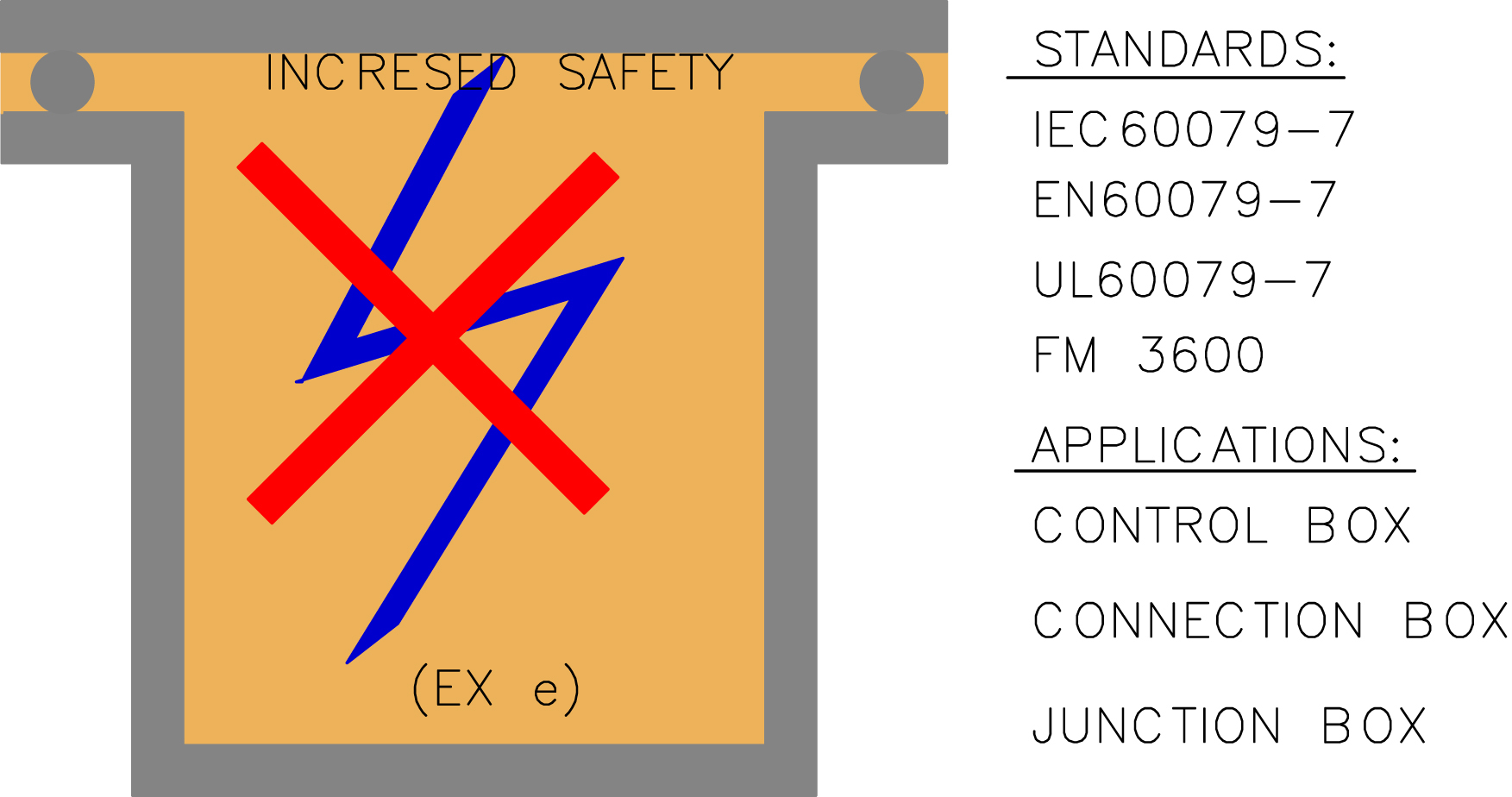
| Increased safety | Ex e | 1, 2 | 2, 3 | No arc, spark, or hot surface |
| Nonsparking | Ex nA | 2 | 3 | No arc, spark, or hot surface |
| Flame proof | Ex d | 1, 2 | 2, 3 | Contains the explosion. Quenches the flame |
| Enclosed break | Ex nW | 2 | 3 | |
| Quartz/sand filled | Ex q | 1, 2 | 2, 3 | Contains the explosion. Quenches the flame |
| Intrinsic safety | Ex ia | 0, 1, 2 | 1, 2, 3 | Limits both the energy of spark and the temperature |
| Intrinsic safety | Ex ib | 1, 2 | 2, 3 | |
| Energy limitation | Ex nL | 2 | 3 | |
| Pressurize | Ex p | 1, 2 | 2, 3 | Keeps the flammable gas from hot surface and ignition-capable equipment |
| Simplified pressurization | Ex nP | 2 | 3 | |
| Encapsulation | Ex m | 1, 2 | 2, 3 | Keeps the flammable gas from hot surface and ignition-capable equipment |
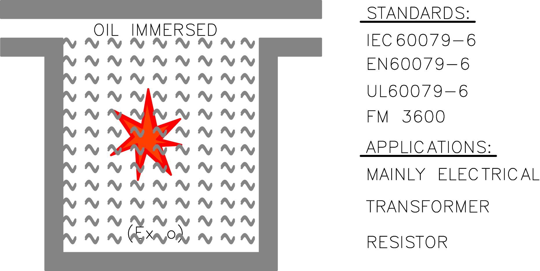
| Oil immersion | Ex o | 1, 2 | 2, 3 | Keeps the flammable gas from hot surface and ignition-capable equipment |
| Restricted breathing | Ex nR | 2 | 3 | |
| Special | Ex s | 0, 1, 2 | 1, 2, 3 | Any proven method |

3.4. Combustible/Flammable Gas Detection
Table X/3.3.4-2
IEC EPL Protection Techniques (Gas) (See Also Appendix II)
| Method | Code Ex | EPL | Zone | IECa | Principle of Protection |
| Increased safety | e | Gb | 1, 2 | 7 | No arc, spark or hot surface. IP54 or better |
| Type n (nonsparking) | nA | Gc | 2 | 15 | |
| Flame proof | d | Gb | 1, 2 | 1 | Contains the explosion. Quenches the flame |
| Type n (enclosed break) | nC | Gc | 2 | 15 | |
| Quartz/sand filled | q | Gb | 1, 2 | 5 | Quenches the flame |
| Intrinsic safety | ia | Ga | 0, 1, 2 | 11 | Limits energy of spark and surface temperature |
| Intrinsic safety | ib | Gb | 1, 2 | 11 | |
| Intrinsic safety | ic | Gc | 2 | 11 | |
| Type n (energy limiting) | nL | Gc | 2 | 15 | |
| Pressurized | p, px | Gb | 1, 2 | 2 | Keeps the flame gas out |
| py | Gb | 1, 2 | 2 | ||
| pz | Gc | 2 | 2 | ||
| Type n (hermetic sealing) | nC | Gc | 2 | 15 | |
| Type n (restricted breathing) | nR | Gc | 2 | 15 | |
| Type n (simple pressurized) | nZ | Gc | 2 | 15 | |
| Encapsulation | ma | Ga | 0, 1, 2 | 18 | Keeps the flame gas out |
| Encapsulation | mb | Gb | 1, 2 | 18 | |
| Oil immersion | o | Gb | 1, 2 | 6 | Keeps the flame gas out |

Table X/3.3.4-3
IEC EPL Protection Techniques (Dust) (See Also Appendix II)
| Method | Code Ex | EPL | Zone | IECa | Principle of Protection |
| Enclosure | t | Da, Db, Dc | 20 | 31 | Standard protection for dust-tight enclosure |
| Intrinsic safety | i | Da, Db, Dc | 21 | 11 | Same as above, some relaxation for intrinsic circuit |
| Encapsulation | m | Da, Db, Dc | 22 | 18 | Protection by encapsulation of incendive part |
| Pressurized | p | Db, Dc | 21, 22 | 2 | Protection by pressurization of enclosure |
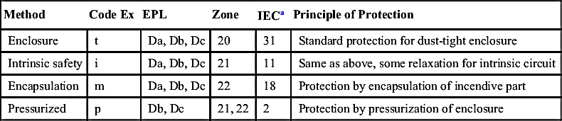
Table X/3.3.4-4
Protection Concepts Class Division System
| Method | Class | Division | Remarks |
| Explosion proof | I | 1, 2 | |
| Dust ignition proof | II | 1, 2 | |
| Dust tight | II | 2 | |
| III | 1, 2 | ||
| Purged and pressurized | – | – | Classified area for which it is identified |
| Intrinsic safety | I | 1, 2 | |
| II | 1, 2 | ||
| III | 1, 2 | ||
| Nonincendive circuit | I | 2 | |
| II | 2 | ||
| III | 1, 2 | ||
| Nonincendive equipment | As above | ||
| Nonincendive component | As above | ||
| Oil immersion | I | 2 | |
| Hermetically sealed | I | 2 | |
| II | 2 | ||
| III | 1, 2 | ||
| Combustible gas detector | Means of protection in industry with restricted public access elec | ||
| Inadequate ventilation | Classified as class 1 division 1 for inadequate ventilation. Electrical apparatus class 1 division 1 | ||

Table X/3.4-1
Differences Between Combustible and Flammable Liquids
| Characteristics | Combustible (Vapor) Liquid | Flammable (Vapor) Liquid |
| Flash point | Flash point >37.8°C | Flash point <37°C Vapor pressure <276 kPa |
| Typical nature | When heated shows many similar characteristic of flammable gas | Volatile vapor heavier than air |
| Nature of vapor | Remains near source till atmospheric temperature > flash point | Flows down in a slope and is collected at low point |
3.4.1. General Properties of a Combustible/Flammable Gas System
3.4.2. Combustible/Flammable Gas Detector


Table X/3.4.2-1
Comparison Between Catalytic Bead and Infrared Instruments
| Points of Comparison | Catalytic Bead Sensing | Infrared Sensing |
| Inert atmosphere | Requires O2 (combustion) | Yes |
| Susceptibility to poison | No | No but less affected |
| Diatomic gas, e.g., H2 | Yes | No |
| Dust and drift immunity | Yes with proper protection | Yes with proper protection |
| O2-enriched condition | Yes | Yes |
| Speed of response | 20–30 s (typical) | <10 s (typical) |
| Cost | Less costly | Higher capital investment |
| Maintenance requirement | High | Low |
3.4.3. Combustible Detector Placements
3.5. Explosion Protection
3.5.1. Basic Protection Principles (Fig. X/3.5.1-1)

3.5.2. Explosion Protection for Fieldbus
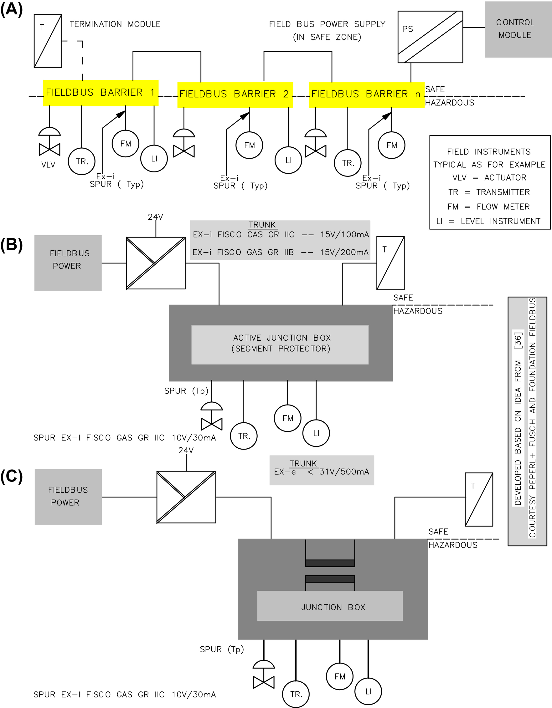


Table X/3.5.2-1
Comparison of Fieldbus Protection by Ex i and Ex nL
| Protection | Code | Fault Tolerance | Applicable Zone |
| Energy limited (see Clause 3.6) | Ex e | 0 | Zone 2 |
| Intrinsic safety ib (see Clause 3.7) | Ex ib | 1 | Zones 1 and 2 |
| Intrinsic safety ia (see Clause 3.7) | Ex ia | 2 | Zones 0, 1, and 2 |

Table X/3.5.2-2
Comparison of Various Fieldbus Protection Concepts [29]
Fieldbus Parameter | IS Entity | FISCO | HPT | FNICO | ||
| Gr. IIB | Gr. IIC | Gr. IIB | Gr. IIC | |||
| Maximum current (mA) | 80 | 265 | 120 | 500 | 320 | 180 |
| Maximum devices | 4 | 13 | 6 | 25 | 16 | 9 |
| Maximum trunk length (ma) | 1900 | 1900 | 1000 | 1900 | 1900 | 1000 |
| Maximum spur length (ma) | 120 | 60 | 60 | 120 | 60 | 60 |
| Hazard zone | 0 and 1 | 1 | 1 | 0 and 1 | 2 | 2 |

3.6. Enclosure Class
3.6.1. Flameproof Enclosure

3.6.2. Increased Safety
3.6.3. Pressurized Enclosure

3.6.4. Oil Immersed
3.6.5. Powder Filling

3.6.6. Encapsulated

3.6.7. Type of Protection “n-”

3.6.8. Ingress Protection


3.6.9. Markings
Table X/3.6.8-1
NEMA Enclosure Rating With Interpretation
| Type | I | O | Protection Against: Personnel Access | Protection (Ingress): Foreign Solid Object | Protection (Ingress): Water Harmful Effect |
| 1 | X | To hazardous part | Falling dirt | ||
| 2 | X | To hazardous part | Falling dirt | Dripping/light splashing | |
| 3 | X | X | To hazardous part | Falling dirt, windblown dust | Rain, sleet, snow, and external ice formation |
| 3R | X | X | To hazardous part | Falling dirt | Rain, sleet, snow, and external ice formation |
| 3S | X | X | To hazardous part | Falling dirt, windblown dust | Rain, sleet, snow. Operable when ice laden |
| 3X | X | X | To hazardous part | Falling dirt, windblown dust | Rain, sleet, snow, and external ice formation and additional corrosion protection |
| 3RX | X | X | To hazardous part | Falling dirt | Rain, sleet, snow, external ice formation, and additional corrosion protection |
| 3SX | X | X | To hazardous part | Falling dirt, windblown dust | Rain, sleet, snow, external ice formation, and additional level of protection for corrosion. Operable when ice laden |
| 4 | X | X | To hazardous part | Falling dirt, windblown dust | Rain, sleet, snow. Splashing and hose-directed water. Undamaged because of external ice formation on enclosure |
| 4X | X | X | To hazardous part | Windblown dust | Rain, sleet, snow. Splashing and hose-directed water. Additional level of protection for corrosion and undamaged because of external ice formation on enclosure |
| Table Continued | |||||

| Type | I | O | Protection Against: Personnel Access | Protection (Ingress): Foreign Solid Object | Protection (Ingress): Water Harmful Effect |
| 5 | X | - | To hazardous part | Falling dirt and settling airborne dust, lint, fibers and flying | Dripping and light splashing |
| 6 | X | X | To hazardous part | Falling dirt | Hose-directed water, entry of water because of occasional temporary submersion at a limited depth, and undamaged because of external ice formation on enclosure |
| 6P | X | X | To hazardous part | Falling dirt | Hose-directed water, entry of water during prolonged submersion at a limited depth. Additional level of protection for corrosion and undamaged because of external ice formation on enclosure |
| 12/12Ka | X | To hazardous part | Falling dirt, circulating dust, lint, fibers, flyings | Dripping/light splashing | |
| 13 | X | To hazardous part | Falling dirt, circulating dust, lint, fibers, flyings | Dripping/light splashing. Also protection against spraying, splashing, and seepage of oil and noncorrosive coolants |


3.7. Intrinsic Safety

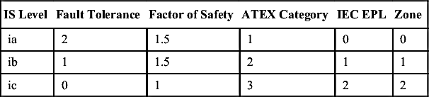
Table X/3.7-1
Comparison and Usage of Intrinsically Safe (IS) Categories
| IS Level | Fault Tolerance | Factor of Safety | ATEX Category | IEC EPL | Zone |
| ia | 2 | 1.5 | 1 | 0 | 0 |
| ib | 1 | 1.5 | 2 | 1 | 1 |
| ic | 0 | 1 | 3 | 2 | 2 |
3.7.1. General Discussions
Table X/3.7.1-1
Parameter Limits for Simple Apparatus (ISA)
| Voltage | Current | Power/Energy |
| 1.2–1.5 V | 0.1 A | 25 mW/20 μJ |
Table X/3.7.1-2
Relation Between Parameters of Barrier and Field Devices
| Barrier Parameter | Relations | Field Device Parameter |
| Open-circuit voltage: Voc | ≤ | Maximum voltage: Vmax |
| Short-circuit current: Isc | ≤ | Maximum current: Imax |
| Allowed capacitance: Ca | ≥ | Internal capacitance: Cia |
| Allowed inductance: La | ≥ | Internal inductance: Lia |


Table X/3.7.1-3
Pros and Cons of Different Approaches to an Intrinsic Safety (IS) Circuit
| Pros and Cons | Grounded IS Barrier | Grounded Repeater | Galvanic Isolator |
| Advantage | Less costly and smaller size Precise signal response | Single product use Usable in transmitters with higher power supply | Single product use No need for ground Usable in transmitters with higher power supply |
| Disadvantage | Precise engineering and grounding are necessary | More expensive, and more power and space needed | More expensive, and more space needed Radiofrequency interference |

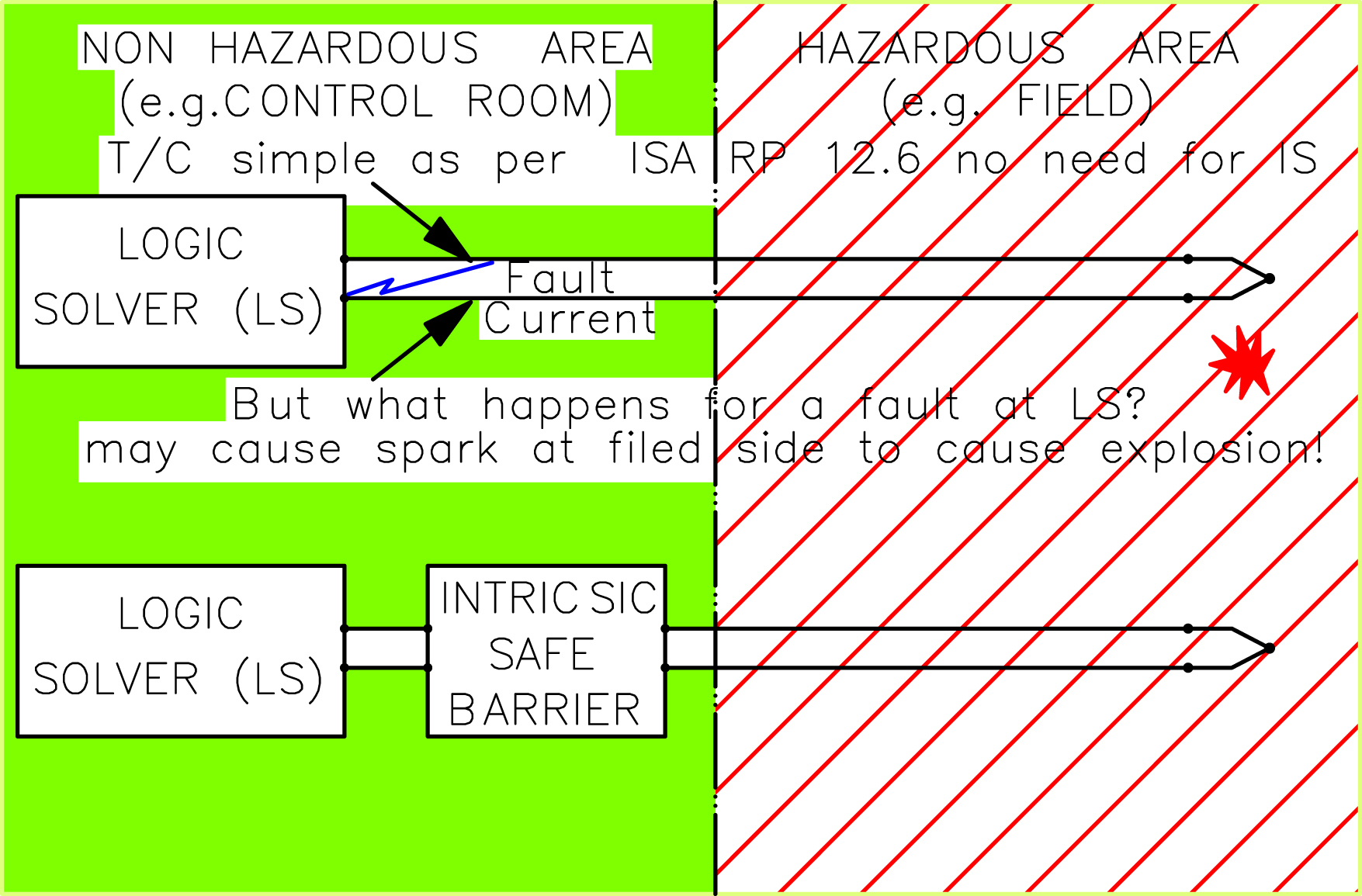
3.7.2. Thermocouple/Resistance Temperature Detector (RTD) Input

3.7.3. Transmitter Input/Analog Input

3.7.4. Digital/Binary Inputs
3.7.5. Analog Output

3.7.6. Digital Output
3.7.7. Wiring and Installation
Table X/3.7.7-1
Short Intrinsic Safety (IS) Cable Specification (General)
| Item | Specification | Item | Specification |
| Conductor | Finely stranded tinned Cu | Sheath color | Light blue (RAL 5015) |
| Insulation | Fluoropolymer/PVC | Standards | IEC 62228/VDE, etc. |
| Cores/pairs | 1, 2, 6, etc. as required | Flame resistance | Flame retardant |
| Screening | Individual/overall | Capacitancea | 100–120 pF/m |
| Screen | Braided wire tinned Cu | Inductance | 0.5 μH/m |
| Outer sheathe | PVC chemical resistant | Voltage rating | 500 V |


