
Engineering Design for Fly Ash Solidification and Stabilization
Abstract
Engineering design for fly ash solidification and stabilization are introduced. In the first case, the engineering design for solidification/stabilization process in China is performed according to the characteristics of original fly ash. The stabilization/solidification process, requirements of the system, technological parameters, equipment, environmental protection, heath, safety and investment estimation of this design, and security landfill for stabilized hazardous wastes are stated in detail. In consideration of the economy and security, solidification with cement and stabilization with chemicals for fly ash is used in most of incineration plants, as landfill became the last procedure. Chemicals like organic chelating agents have proven to be the best choice, with respect to its performance or stability. Hence, organic polymer chelating agent stabilization treatment plus cement solidification process is recommended in real projects. The fly ash, chelating agent and cement are mixed in the mixer, the heavy metals in the fly ash can take complexation reactions with chelating agent and generate insoluble substance to reach stabilization. Parameters details and equipment as well as automatic installations for fly ash stabilization and solidification are listed.
Keywords
Fly ash; solidification and stabilization engineering design; system requirement; economic evaluation; system parameter; security landfill
9.1 Characteristics of The Original Fly Ash
This case study describes the solidification/stabilization and landfill of fly ash generated in Laogang municipal solid waste incinerator, Shanghai, China (121.879E, 31.057N). As one of the largest MSWI in China, four furnaces burn 3000 t of urban garbage every day, and meanwhile produce 100–150 t of fly ashes from flue gas purification system, which are chosen to be solidified/stabilized and transported to landfill subsequently. The characteristics of original fly ash, the choice of agent, the pretreatment and landfill process are introduced and the whole project is operated by Shanghai Laogang Waste Disposal Co., Ltd.
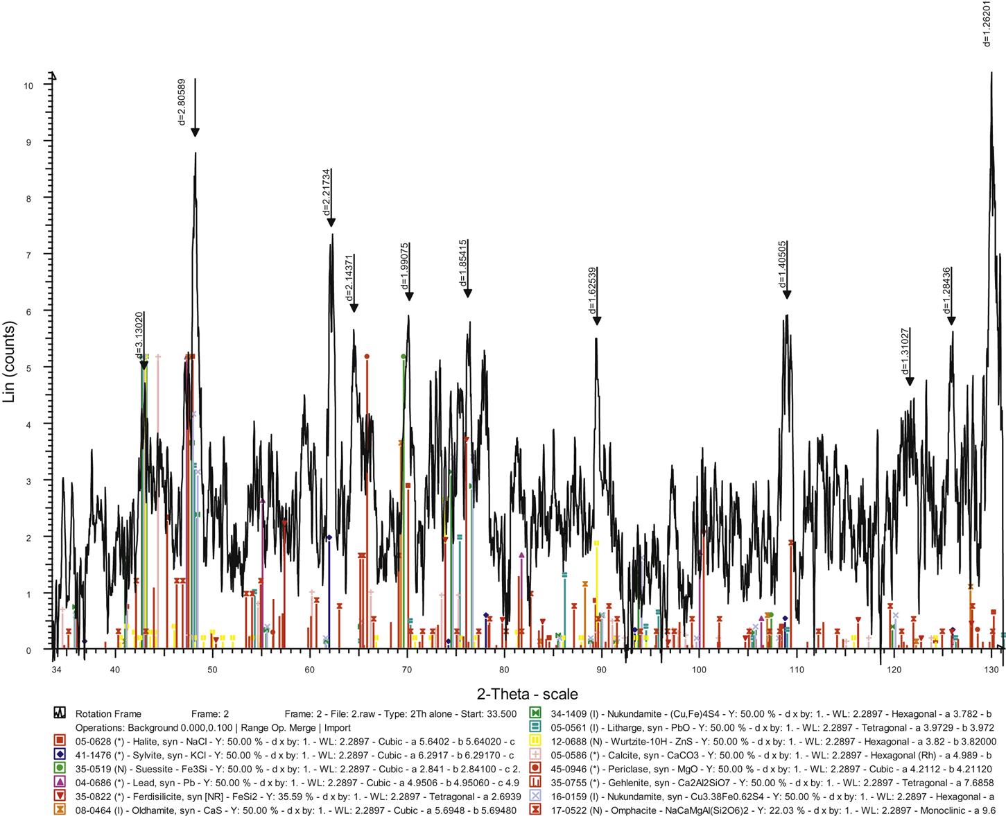
The physical properties of original fly ash are summarized in Table 9.1. Most of the particles are smaller than 0.074 mm (Table 9.2), thus there is no need for grinding before solidification. The main elements of fly ash were Ca, Fe, Mg, Na, K, Cl, C, and S. In the process of flue gas purification system, the addition of lime possibly increased the content of Ca. Results showed that around one third of cations, such as Na, K, Ca, and Mg, bonded with S and Cl instead of O and the remaining Ca, Mg is in the form of oxides, hydroxides, alkali silicate and alkali aluminate at the same time (Fig. 9.1). Further analysis demonstrated that the main content of fly ash were SiO2, Al2SiO5, NaCl, KCl, CaAl2Si2O8, Zn2SiO4, CaCO3 and CaSO4 with a small amount of CaO, Ca2Al2SiO7, PbO, Cu2CrO4 (Figs. 9.1 and 9.2).
Table 9.1
Physical Properties of Original Fly Ash
| Sample | 1 | 2 | 3 | 4 | 5 | 6 | |
| Specific gravity (kN/m3) | 2.71 | 2.65 | 2.81 | 2.75 | 2.76 | 2.66 | |
| Density (g/cm3) | Dumping loosely | 0.60 | 0.56 | 0.64 | 0.62 | 0.62 | 0.57 |
| Compaction (50 KPa) | 0.66 | 0.62 | 0.69 | 0.67 | 0.67 | 0.63 | |
| Compaction (100 KPa) | 0.73 | 0.69 | 0.75 | 0.74 | 0.74 | 0.70 | |
| Compaction (200 KPa) | 0.97 | 0.90 | 1.08 | 1.01 | 1.01 | 0.91 | |
| Ignition loss (%) | 5.38 | 5.15 | 5.86 | 5.58 | 5.56 | 5.26 | |
| Sample | 7 | 8 | 9 | 10 | 11 | 12 | |
| Specific gravity (kN/m3) | 2.78 | 2.55 | 2.73 | 2.68 | 2.70 | 2.78 | |
| Density (g/cm3) | Dumping loosely | 0.63 | 0.44 | 0.61 | 0.58 | 0.59 | 0.63 |
| Compaction (50 KPa) | 0.68 | 0.50 | 0.68 | 0.64 | 0.65 | 0.70 | |
| Compaction (100 KPa) | 0.75 | 0.58 | 0.75 | 0.72 | 0.72 | 0.76 | |
| Compaction (200 KPa) | 1.03 | 0.81 | 0.92 | 0.90 | 0.94 | 0.99 | |
| Ignition loss (%) | 5.58 | 5.02 | 5.23 | 5.20 | 5.21 | 5.60 | |
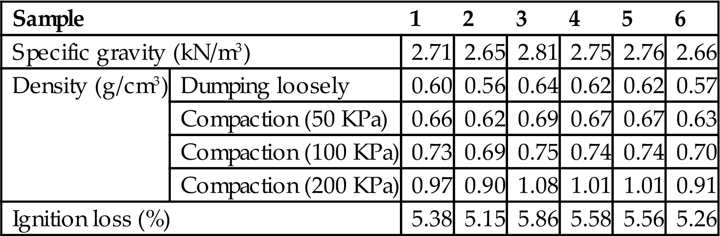
Table 9.2
The Proportion of Size Ranges of Fly Ash
| Size (mm) | 2.0 | 2.0–0.5 | 0.5–0.25 | 0.25–0.074 | 0.074–0.005 | <0.005 |
| Proportion (%) | 0.0 | 0.0 | 0.0 | 28.0 | 61.8 | 10.2 |


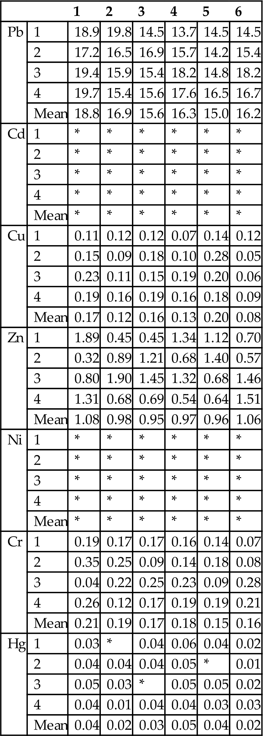
Heavy metals and properties of fly ash are shown in Tables 9.1–9.4. The standard limit of leaching toxicity of hazardous waste in China is presented in Table 9.5. According the method of leaching toxicity of fly ash (GB5086-1997), the results are shown in Table 9.6. It can be seen that the leaching amount of most heavy metals were below standard limit except Pb.
Table 9.3
Elemental Composition of Fly Ash
| Element | Content | Element | Content | ||
| Alkali metal | Ca | 232 | Heavy metal | Pb | 3.2 |
| Mg | 16.9 | Cd | 0.07 | ||
| K | 31.5 | Cu | 0.63 | ||
| Na | 42.3 | Zn | 3.9 | ||
| Matrix | Al | * | Cr | 0.17 | |
| Fe | 18.9 | C | 14.9 | ||
| Si | * | Cl | 103 | ||
| Unit: Mg/g | S | 22.5 | |||

Fig. 3-63 Form of Cd and Cu in fly ash.
Table 9.
Contents of Heavy Metals in Fly Ash
| mg/kg | 1 | 2 | 3 | 4 | 5 | 6 |
| Pb | 3231.0 | 3182.7 | 2989.5 | 3093.5 | 2835.6 | 3026.4 |
| Cd | 65.8 | 58.7 | 68.9 | 79.2 | 68.2 | 72.8 |
| Cu | 629.1 | 598.8 | 639.8 | 584.2 | 681.5 | 456.9 |
| Zn | 3942.4 | 3789.5 | 3512.4 | 3641.2 | 3865.5 | 3765.4 |
| Ni | 72.5 | 68.5 | 65.1 | 74.9 | 65.9 | 69.5 |
| Cr | 172.6 | 165.9 | 155.2 | 154.5 | 156.5 | 154.4 |
| Hg | 14.3 | 9.8 | 6.4 | 15.2 | 19.6 | 4.9 |
| mg/kg | 7 | 8 | 9 | 10 | 11 | 12 |
| Pb | 2913.0 | 3125.5 | 3225.6 | 3782.1 | 2956.2 | 3169.2 |
| Cd | 56.8 | 54.8 | 65.8 | 56.4 | 66.5 | 58.9 |
| Cu | 645.1 | 569.5 | 596.3 | 564.2 | 561.2 | 619.2 |
| Zn | 3546.4 | 3495.6 | 3697.8 | 4368.9 | 3859.6 | 3467.9 |
| Ni | 52.5 | 76.5 | 78.2 | 54.5 | 72.6 | 73.6 |
| Cr | 162.8 | 175.6 | 156.5 | 145.5 | 175.6 | 174.5 |
| Hg | 8.3 | 11.9 | 10.6 | 4.7 | 11.5 | 5.6 |

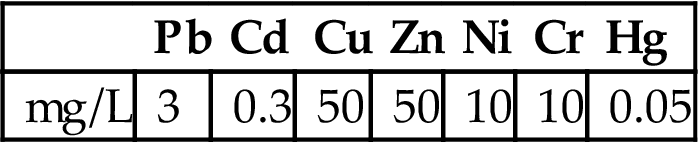
Table 9.6
Fly Ash Leaching Toxicity Measurement Results (mg/L)
| 1 | 2 | 3 | 4 | 5 | 6 | ||
| Pb | 1 | 18.9 | 19.8 | 14.5 | 13.7 | 14.5 | 14.5 |
| 2 | 17.2 | 16.5 | 16.9 | 15.7 | 14.2 | 15.4 | |
| 3 | 19.4 | 15.9 | 15.4 | 18.2 | 14.8 | 18.2 | |
| 4 | 19.7 | 15.4 | 15.6 | 17.6 | 16.5 | 16.7 | |
| Mean | 18.8 | 16.9 | 15.6 | 16.3 | 15.0 | 16.2 | |
| Cd | 1 | * | * | * | * | * | * |
| 2 | * | * | * | * | * | * | |
| 3 | * | * | * | * | * | * | |
| 4 | * | * | * | * | * | * | |
| Mean | * | * | * | * | * | * | |
| Cu | 1 | 0.11 | 0.12 | 0.12 | 0.07 | 0.14 | 0.12 |
| 2 | 0.15 | 0.09 | 0.18 | 0.10 | 0.28 | 0.05 | |
| 3 | 0.23 | 0.11 | 0.15 | 0.19 | 0.20 | 0.06 | |
| 4 | 0.19 | 0.16 | 0.19 | 0.16 | 0.18 | 0.09 | |
| Mean | 0.17 | 0.12 | 0.16 | 0.13 | 0.20 | 0.08 | |
| Zn | 1 | 1.89 | 0.45 | 0.45 | 1.34 | 1.12 | 0.70 |
| 2 | 0.32 | 0.89 | 1.21 | 0.68 | 1.40 | 0.57 | |
| 3 | 0.80 | 1.90 | 1.45 | 1.32 | 0.68 | 1.46 | |
| 4 | 1.31 | 0.68 | 0.69 | 0.54 | 0.64 | 1.51 | |
| Mean | 1.08 | 0.98 | 0.95 | 0.97 | 0.96 | 1.06 | |
| Ni | 1 | * | * | * | * | * | * |
| 2 | * | * | * | * | * | * | |
| 3 | * | * | * | * | * | * | |
| 4 | * | * | * | * | * | * | |
| Mean | * | * | * | * | * | * | |
| Cr | 1 | 0.19 | 0.17 | 0.17 | 0.16 | 0.14 | 0.07 |
| 2 | 0.35 | 0.25 | 0.09 | 0.14 | 0.18 | 0.08 | |
| 3 | 0.04 | 0.22 | 0.25 | 0.23 | 0.09 | 0.28 | |
| 4 | 0.26 | 0.12 | 0.17 | 0.19 | 0.19 | 0.21 | |
| Mean | 0.21 | 0.19 | 0.17 | 0.18 | 0.15 | 0.16 | |
| Hg | 1 | 0.03 | * | 0.04 | 0.06 | 0.04 | 0.02 |
| 2 | 0.04 | 0.04 | 0.04 | 0.05 | * | 0.01 | |
| 3 | 0.05 | 0.03 | * | 0.05 | 0.05 | 0.02 | |
| 4 | 0.04 | 0.01 | 0.04 | 0.04 | 0.03 | 0.03 | |
| Mean | 0.04 | 0.02 | 0.03 | 0.05 | 0.04 | 0.02 |
| 7 | 8 | 9 | 10 | 11 | 12 | ||
| Pb | 1 | 16.9 | 13.5 | 19.3 | 20.1 | 18.1 | 16.2 |
| 2 | 15.4 | 21.2 | 18.4 | 24.2 | 12.6 | 14.8 | |
| 3 | 17.2 | 14.8 | 19.1 | 20.5 | 15.4 | 15.2 | |
| 4 | 13.7 | 22.1 | 17.6 | 20.4 | 18.7 | 17.0 | |
| Mean | 15.8 | 17.9 | 18.6 | 21.3 | 16.2 | 15.8 | |
| Cd | 1 | * | * | * | * | * | * |
| 2 | * | * | * | * | * | * | |
| 3 | * | * | * | * | * | * | |
| 4 | * | * | * | * | * | * | |
| Mean | * | * | * | * | * | * | |
| Cu | 1 | 0.12 | 0.10 | 0.22 | 0.11 | 0.24 | 0.02 |
| 2 | 0.17 | 0.12 | 0.15 | 0.14 | 0.23 | 0.15 | |
| 3 | 0.19 | 0.19 | 0.20 | 0.15 | 0.12 | 0.12 | |
| 4 | 0.12 | 0.15 | 0.11 | 0.12 | 0.17 | 0.07 | |
| Mean | 0.15 | 0.14 | 0.17 | 0.13 | 0.19 | 0.09 | |
| Zn | 1 | 1.12 | 0.89 | 0.87 | 1.21 | 1.02 | 1.01 |
| 2 | 1.15 | 0.93 | 0.99 | 1.09 | 1.12 | 0.85 | |
| 3 | 0.98 | 1.2 | 1.12 | 1.15 | 1.06 | 0.98 | |
| 4 | 0.83 | 0.94 | 0.94 | 1.23 | 1.04 | 1.48 | |
| Mean | 1.02 | 0.99 | 0.98 | 1.17 | 1.06 | 1.08 | |
| Ni | 1 | * | * | * | * | * | * |
| 2 | * | * | * | * | * | * | |
| 3 | * | * | * | * | * | * | |
| 4 | * | * | * | * | * | * | |
| Mean | * | * | * | * | * | * | |
| Cr | 1 | 0.12 | 0.18 | 0.11 | 0.17 | 0.19 | 0.21 |
| 2 | 0.17 | 0.18 | 0.14 | 0.11 | 0.15 | 0.12 | |
| 3 | 0.13 | 0.15 | 0.25 | 0.18 | 0.21 | 0.24 | |
| 4 | 0.18 | 0.25 | 0.14 | 0.14 | 0.13 | 0.15 | |
| Mean | 0.15 | 0.19 | 0.16 | 0.15 | 0.17 | 0.18 | |
| Hg | 1 | 0.01 | 0.06 | 0.05 | 0.01 | 0.04 | 0.01 |
| 2 | 0.04 | 0.02 | 0.05 | 0.02 | 0.02 | 0.03 | |
| 3 | 0.04 | 0.03 | 0.05 | 0.01 | 0.03 | 0.02 | |
| 4 | 0.03 | 0.05 | 0.05 | * | 0.06 | 0.02 | |
| Mean | 0.03 | 0.04 | 0.05 | 0.01 | 0.05 | 0.02 |

9.2 Chemical Stabilization Tests of Fly Ash
The stabilization steps can be described as follows.
![]() 100 g of fly ash and 1, 2, 3, 4 and 5% of amounts of fly ash are mixed and stirred for almost 10–20 min.
100 g of fly ash and 1, 2, 3, 4 and 5% of amounts of fly ash are mixed and stirred for almost 10–20 min.
![]() Leaching experiment is carried out.
Leaching experiment is carried out.
![]() After the solid–liquid separation, the concentration of heavy metals in solution is determined.
After the solid–liquid separation, the concentration of heavy metals in solution is determined.
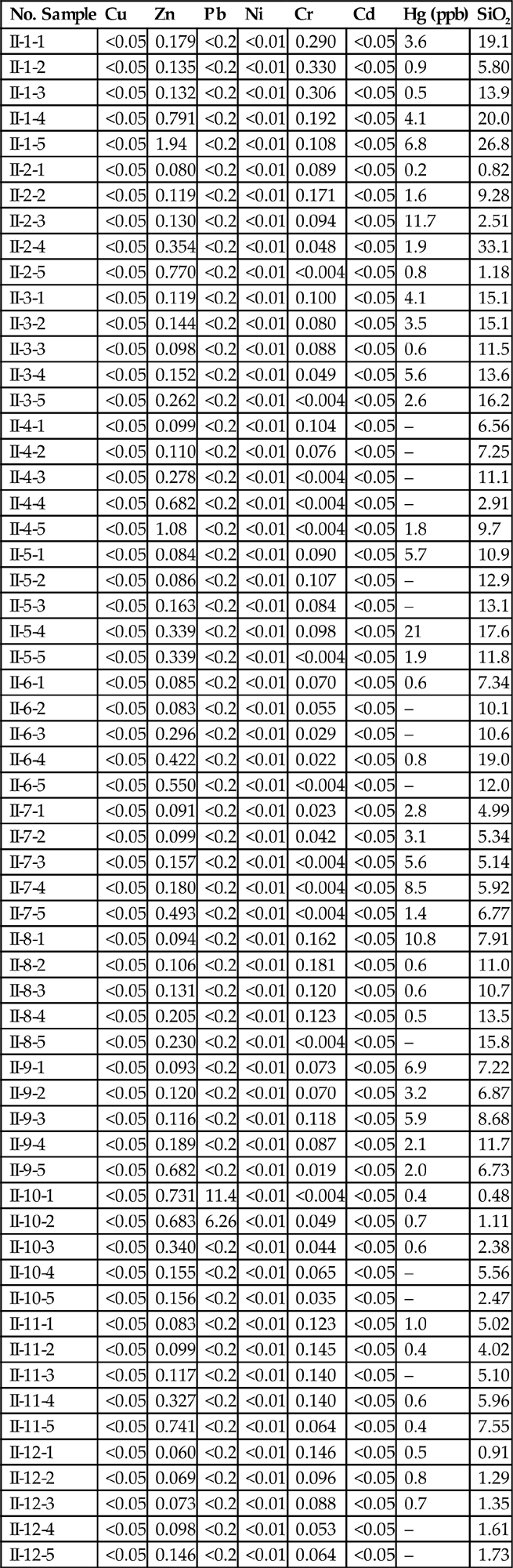
In the tests, two kinds of stabilizing agents were performed. Five different amounts of agents were tested in duplicate. The leaching results of the first agents and the second one (liquid phosphorus and sulfur chelating agents, with complex components) are respectively shown in Tables 9.7 and 9.8. The dosage of two agents was nearly equal. According to the test results, stabilization effect of the first agent was slightly better than that of the second one.
Table 9.7
Leaching Toxicity Analysis Results of the Stabilized Fly Ash Using the First Chelating Agent (mg/L)
| No. Sample | Cu | Zn | Pb | Ni | Cr | Cd | Hg (ppb) | Ca | Mg | K | Na |
| I-1-1 | <0.05 | 0.118 | <0.2 | <0.01 | 0.177 | <0.05 | 3.8 | 2275 | 1.79 | 2110 | – |
| I-1-2 | <0.05 | 0.109 | <0.2 | <0.01 | 0.196 | <0.05 | 0.2 | 2115 | 1.64 | 1940 | – |
| I-1-3 | <0.05 | 0.149 | <0.2 | <0.01 | 0.105 | <0.05 | 0.8 | 2375 | 1.63 | 2240 | – |
| I-1-4 | <0.05 | 0.341 | <0.2 | <0.01 | <0.004 | <0.05 | 4.5 | 2163 | 1.61 | 2080 | – |
| I-1-5 | <0.05 | 0.465 | <0.2 | <0.01 | <0.004 | <0.05 | 9.8 | 1878 | 1.72 | 1750 | – |
| I-2-1 | <0.05 | 0.098 | <0.2 | <0.01 | 0.079 | <0.05 | 0.2 | 1646 | 0.76 | 2230 | – |
| I-2-2 | <0.05 | 0.104 | <0.2 | <0.01 | 0.083 | <0.05 | 12.6 | 1482 | 0.639 | 1870 | – |
| I-2-3 | <0.05 | 0.092 | <0.2 | <0.01 | 0.08 | <0.05 | 1.9 | 1670 | 0.663 | 2170 | – |
| I-2-4 | <0.05 | 0.21 | <0.2 | <0.01 | 0.06 | <0.05 | 1.9 | 1682 | 0.792 | 2350 | – |
| I-2-5 | <0.05 | 0.321 | <0.2 | <0.01 | <0.004 | <0.05 | 0.6 | 1658 | 0.610 | 2290 | – |
| I-3-1 | <0.05 | 0.084 | <0.2 | <0.01 | <0.004 | <0.05 | 5.1 | 1268 | 0.498 | 3180 | – |
| I-3-2 | <0.05 | 0.098 | <0.2 | <0.01 | 0.061 | <0.05 | 4.5 | 1241 | 0.391 | 3110 | – |
| I-3-3 | <0.05 | 0.088 | <0.2 | <0.01 | 0.066 | <0.05 | 0.4 | 1201 | 0.437 | 3060 | – |
| I-3-4 | <0.05 | 0.213 | <0.2 | <0.01 | <0.004 | <0.05 | 5.4 | 1245 | 0.571 | 3230 | – |
| I-3-5 | <0.05 | 0.504 | <0.2 | <0.01 | <0.004 | <0.05 | – | 1270 | 0.435 | 3460 | – |
| I-4-1 | <0.05 | 0.099 | <0.2 | <0.01 | 0.052 | <0.05 | 11.6 | 2143 | 0.270 | 1950 | – |
| I-4-2 | <0.05 | 0.106 | <0.2 | <0.01 | 0.063 | <0.05 | – | 2227 | 0.148 | 2100 | – |
| I-4-3 | <0.05 | 0.104 | <0.2 | <0.01 | 0.06 | <0.05 | – | 2163 | 0.176 | 2080 | – |
| I-4-4 | <0.05 | 0.189 | <0.2 | <0.01 | <0.004 | <0.05 | – | 2183 | 0.272 | 2070 | – |
| I-4-5 | <0.05 | 0.366 | <0.2 | <0.01 | <0.004 | <0.05 | 19.8 | 2123 | 0.159 | 2020 | – |
| I-5-1 | <0.05 | 0.128 | <0.2 | <0.01 | 0.048 | <0.05 | 52.7 | 1270 | 0.738 | 2900 | – |
| I-5-2 | <0.05 | 0.091 | <0.2 | <0.01 | 0.048 | <0.05 | – | 1217 | 0.176 | 2760 | – |
| I-5-3 | <0.05 | 0.093 | <0.2 | <0.01 | 0.059 | <0.05 | – | 1221 | 0.210 | 2910 | – |
| I-5-4 | <0.05 | 0.205 | <0.2 | <0.01 | 0.029 | <0.05 | 23 | 1270 | 0.340 | 3080 | – |
| I-5-5 | <0.05 | 0.434 | <0.2 | <0.01 | <0.004 | <0.05 | 11.9 | 1249 | 0.420 | 2920 | – |
| I-6-1 | <0.05 | 0.091 | <0.2 | 0.02 | 0.051 | <0.05 | 0.1 | 2823 | <0.002 | 2750 | – |
| I-6-2 | <0.05 | 0.096 | <0.2 | <0.01 | 0.038 | <0.05 | – | 2719 | <0.002 | 2690 | – |
| I-6-3 | <0.05 | 0.098 | <0.2 | <0.01 | 0.04 | <0.05 | – | 2583 | 0.047 | 2500 | – |
| I-6-4 | <0.05 | 0.143 | <0.2 | <0.01 | <0.004 | <0.05 | 0.9 | 2431 | <0.002 | 2390 | – |
| I-6-5 | <0.05 | 0.256 | <0.2 | <0.01 | <0.004 | <0.05 | 0.7 | 2443 | <0.002 | 2380 | – |
| I-7-1 | <0.05 | 0.089 | <0.2 | <0.01 | 0.118 | <0.05 | 2.9 | 1798 | 0.391 | 2820 | – |
| I-7-2 | <0.05 | 0.085 | <0.2 | <0.01 | 0.072 | <0.05 | 3.2 | 1766 | 0.362 | 2850 | – |
| I-7-3 | <0.05 | 0.091 | <0.2 | <0.01 | 0.072 | <0.05 | 5.1 | 1770 | 0.304 | 2860 | – |
| I-7-4 | <0.05 | 0.265 | <0.2 | <0.01 | 0.022 | <0.05 | 8.3 | 1758 | 0.580 | 2900 | – |
| I-7-5 | <0.05 | 0.268 | <0.2 | <0.01 | <0.004 | <0.05 | 14.4 | 1774 | 0.464 | 2960 | – |
| I-8-1 | <0.05 | 0.100 | <0.2 | <0.01 | <0.004 | <0.05 | 0.8 | 1568 | 0.548 | 2513 | – |
| I-8-2 | 0.05 | 0.107 | <0.2 | <0.01 | 0.158 | <0.05 | 0.6 | 1484 | 0.621 | 2781 | – |
| I-8-3 | <0.05 | 0.107 | <0.2 | <0.01 | 0.098 | <0.05 | 0.2 | 1497 | 0.385 | 2287 | – |
| I-8-4 | 0.348 | 0.174 | <0.2 | <0.01 | 0.143 | <0.05 | – | 1848 | 0.462 | 2965 | – |
| I-8-5 | <0.05 | 0.275 | <0.2 | <0.01 | 0.035 | <0.05 | – | 1698 | 0.576 | 2487 | – |
| I-9-1 | <0.05 | 0.090 | <0.2 | <0.01 | 0.050 | <0.05 | 6.8 | 2154 | 0.369 | 2698 | – |
| I-9-2 | <0.05 | 0.114 | <0.2 | <0.01 | 0.102 | <0.05 | 5.3 | 2036 | 0.348 | 2486 | – |
| I-9-3 | <0.05 | 0.156 | <0.2 | <0.01 | 0.103 | <0.05 | 5.0 | 1887 | 0.845 | 2854 | – |
| I-9-4 | <0.05 | 0.247 | <0.2 | <0.01 | 0.043 | <0.05 | 2.3 | 1468 | 0.625 | 2745 | – |
| I-9-5 | <0.05 | 0.513 | <0.2 | <0.01 | 0.073 | <0.05 | 2.0 | 1399 | 0.647 | 2698 | – |
| I-10-1 | <0.05 | 0.980 | 9.74 | <0.01 | <0.004 | <0.05 | 0.9 | 1892 | 0.384 | 2496 | – |
| I-10-2 | <0.05 | 1.40 | 4.54 | <0.01 | 0.038 | <0.05 | 0.6 | 1942 | 0.542 | 2895 | – |
| I-10-3 | <0.05 | 0.531 | <0.2 | <0.01 | 0.052 | <0.05 | 0.3 | 1654 | 0.482 | 2598 | – |
| I-10-4 | <0.05 | 0.182 | <0.2 | <0.01 | 0.096 | <0.05 | – | 1892 | 0.758 | 2785 | – |
| I-10-5 | <0.05 | 0.171 | <0.2 | <0.01 | 0.050 | <0.05 | – | 1684 | 0.423 | 2475 | – |
| I-11-1 | <0.05 | 0.095 | <0.2 | <0.01 | 0.138 | <0.05 | 2.0 | 2045 | 0.396 | 2645 | – |
| I-11-2 | <0.05 | 0.085 | <0.2 | <0.01 | 0.102 | <0.05 | 0.8 | 1320 | 0.384 | 2738 | – |
| I-11-3 | <0.05 | 0.159 | <0.2 | <0.01 | 0.081 | <0.05 | – | 1795 | 0.542 | 2813 | – |
| I-11-4 | <0.05 | 0.323 | <0.2 | <0.01 | 0.094 | <0.05 | 0.2 | 1587 | 0.412 | 2945 | – |
| I-11-5 | <0.05 | 0.741 | <0.2 | <0.01 | 0.025 | <0.05 | 0.1 | 1489 | 0.437 | 2635 | – |
| I-12-1 | <0.05 | 0.059 | <0.2 | <0.01 | 0.136 | <0.05 | 0.9 | 1684 | 0.385 | 2695 | – |
| I-12-2 | <0.05 | 0.091 | <0.2 | <0.01 | 0.060 | <0.05 | – | 1288 | 0.421 | 2487 | – |
| I-12-3 | <0.05 | 0.082 | <0.2 | <0.01 | 0.042 | <0.05 | 0.6 | 1879 | 0.376 | 2956 | – |
| I-12-4 | <0.05 | 0.086 | <0.2 | <0.01 | 0.074 | <0.05 | – | 1654 | 0.374 | 2487 | – |
| I-12-5 | <0.05 | 0.128 | <0.2 | <0.01 | 0.051 | <0.05 | – | 1785 | 0.386 | 2684 | – |
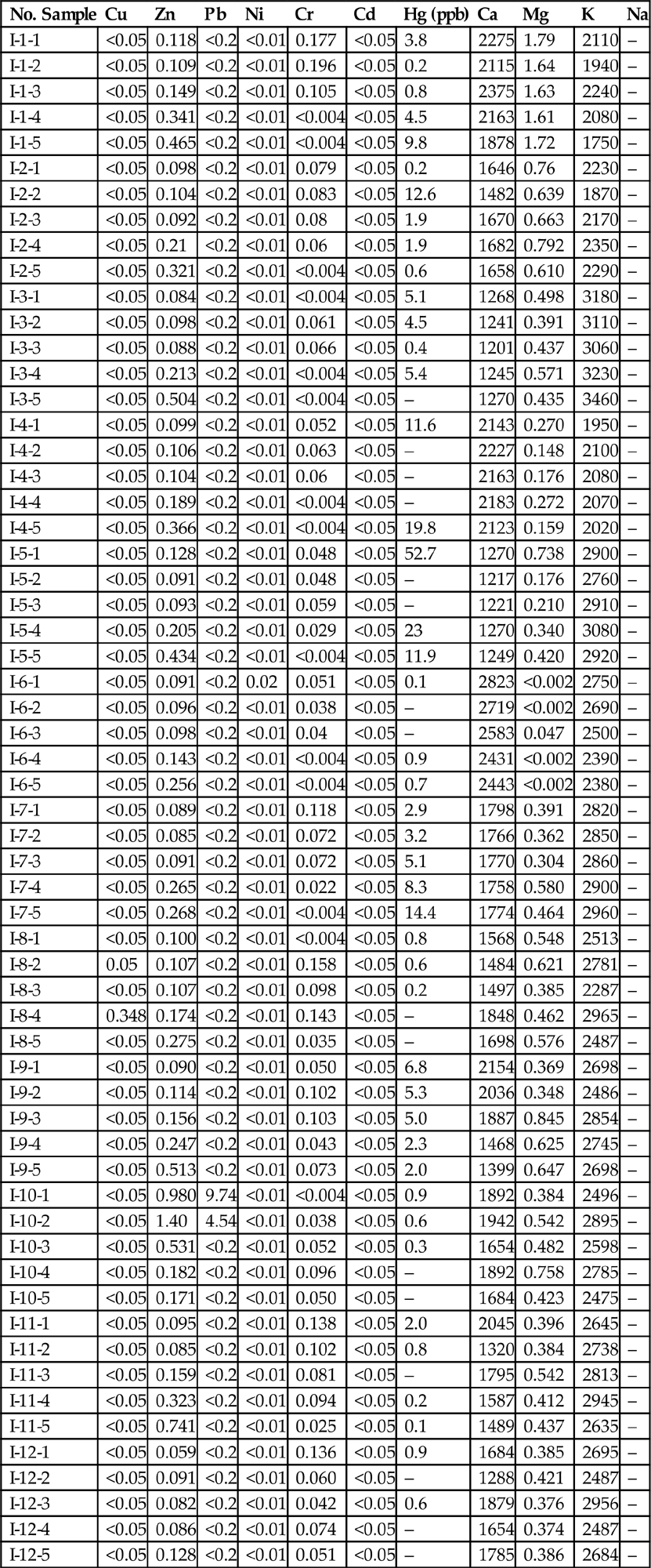
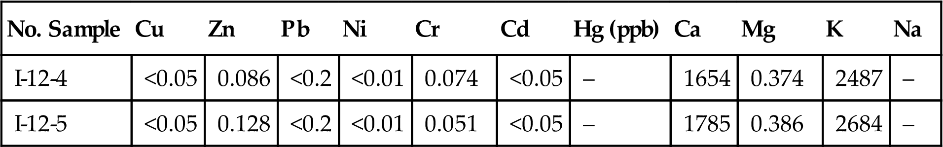
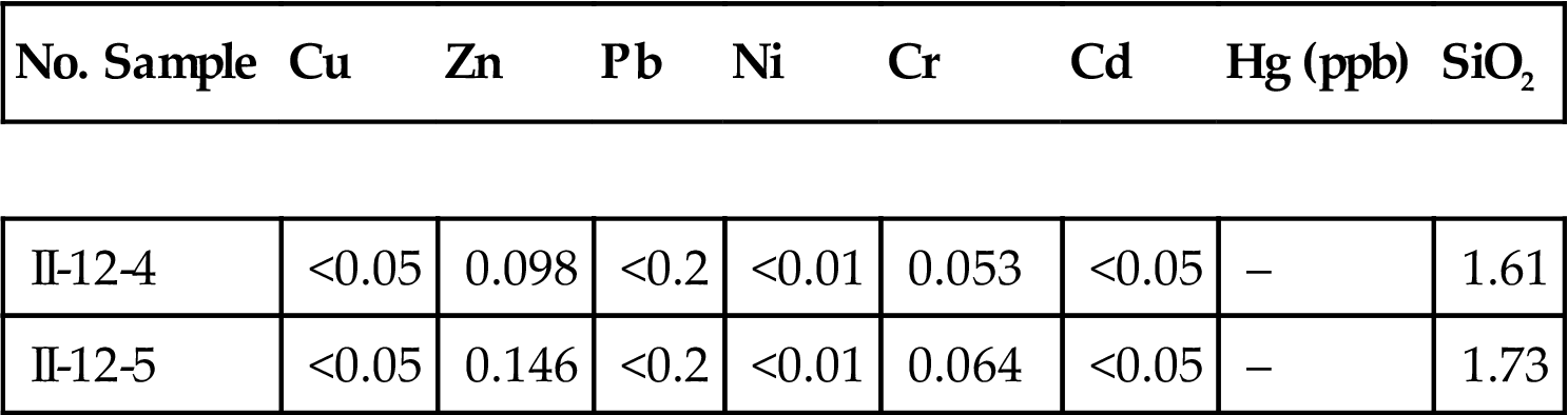
Table 9.8
Leaching Toxicity Analysis Results of the Stabilized Fly Ash Using the Second Chelating Agent (mg/L)
| No. Sample | Cu | Zn | Pb | Ni | Cr | Cd | Hg (ppb) | SiO2 |
| II-1-1 | <0.05 | 0.179 | <0.2 | <0.01 | 0.290 | <0.05 | 3.6 | 19.1 |
| II-1-2 | <0.05 | 0.135 | <0.2 | <0.01 | 0.330 | <0.05 | 0.9 | 5.80 |
| II-1-3 | <0.05 | 0.132 | <0.2 | <0.01 | 0.306 | <0.05 | 0.5 | 13.9 |
| II-1-4 | <0.05 | 0.791 | <0.2 | <0.01 | 0.192 | <0.05 | 4.1 | 20.0 |
| II-1-5 | <0.05 | 1.94 | <0.2 | <0.01 | 0.108 | <0.05 | 6.8 | 26.8 |
| II-2-1 | <0.05 | 0.080 | <0.2 | <0.01 | 0.089 | <0.05 | 0.2 | 0.82 |
| II-2-2 | <0.05 | 0.119 | <0.2 | <0.01 | 0.171 | <0.05 | 1.6 | 9.28 |
| II-2-3 | <0.05 | 0.130 | <0.2 | <0.01 | 0.094 | <0.05 | 11.7 | 2.51 |
| II-2-4 | <0.05 | 0.354 | <0.2 | <0.01 | 0.048 | <0.05 | 1.9 | 33.1 |
| II-2-5 | <0.05 | 0.770 | <0.2 | <0.01 | <0.004 | <0.05 | 0.8 | 1.18 |
| II-3-1 | <0.05 | 0.119 | <0.2 | <0.01 | 0.100 | <0.05 | 4.1 | 15.1 |
| II-3-2 | <0.05 | 0.144 | <0.2 | <0.01 | 0.080 | <0.05 | 3.5 | 15.1 |
| II-3-3 | <0.05 | 0.098 | <0.2 | <0.01 | 0.088 | <0.05 | 0.6 | 11.5 |
| II-3-4 | <0.05 | 0.152 | <0.2 | <0.01 | 0.049 | <0.05 | 5.6 | 13.6 |
| II-3-5 | <0.05 | 0.262 | <0.2 | <0.01 | <0.004 | <0.05 | 2.6 | 16.2 |
| II-4-1 | <0.05 | 0.099 | <0.2 | <0.01 | 0.104 | <0.05 | – | 6.56 |
| II-4-2 | <0.05 | 0.110 | <0.2 | <0.01 | 0.076 | <0.05 | – | 7.25 |
| II-4-3 | <0.05 | 0.278 | <0.2 | <0.01 | <0.004 | <0.05 | – | 11.1 |
| II-4-4 | <0.05 | 0.682 | <0.2 | <0.01 | <0.004 | <0.05 | – | 2.91 |
| II-4-5 | <0.05 | 1.08 | <0.2 | <0.01 | <0.004 | <0.05 | 1.8 | 9.7 |
| II-5-1 | <0.05 | 0.084 | <0.2 | <0.01 | 0.090 | <0.05 | 5.7 | 10.9 |
| II-5-2 | <0.05 | 0.086 | <0.2 | <0.01 | 0.107 | <0.05 | – | 12.9 |
| II-5-3 | <0.05 | 0.163 | <0.2 | <0.01 | 0.084 | <0.05 | – | 13.1 |
| II-5-4 | <0.05 | 0.339 | <0.2 | <0.01 | 0.098 | <0.05 | 21 | 17.6 |
| II-5-5 | <0.05 | 0.339 | <0.2 | <0.01 | <0.004 | <0.05 | 1.9 | 11.8 |
| II-6-1 | <0.05 | 0.085 | <0.2 | <0.01 | 0.070 | <0.05 | 0.6 | 7.34 |
| II-6-2 | <0.05 | 0.083 | <0.2 | <0.01 | 0.055 | <0.05 | – | 10.1 |
| II-6-3 | <0.05 | 0.296 | <0.2 | <0.01 | 0.029 | <0.05 | – | 10.6 |
| II-6-4 | <0.05 | 0.422 | <0.2 | <0.01 | 0.022 | <0.05 | 0.8 | 19.0 |
| II-6-5 | <0.05 | 0.550 | <0.2 | <0.01 | <0.004 | <0.05 | – | 12.0 |
| II-7-1 | <0.05 | 0.091 | <0.2 | <0.01 | 0.023 | <0.05 | 2.8 | 4.99 |
| II-7-2 | <0.05 | 0.099 | <0.2 | <0.01 | 0.042 | <0.05 | 3.1 | 5.34 |
| II-7-3 | <0.05 | 0.157 | <0.2 | <0.01 | <0.004 | <0.05 | 5.6 | 5.14 |
| II-7-4 | <0.05 | 0.180 | <0.2 | <0.01 | <0.004 | <0.05 | 8.5 | 5.92 |
| II-7-5 | <0.05 | 0.493 | <0.2 | <0.01 | <0.004 | <0.05 | 1.4 | 6.77 |
| II-8-1 | <0.05 | 0.094 | <0.2 | <0.01 | 0.162 | <0.05 | 10.8 | 7.91 |
| II-8-2 | <0.05 | 0.106 | <0.2 | <0.01 | 0.181 | <0.05 | 0.6 | 11.0 |
| II-8-3 | <0.05 | 0.131 | <0.2 | <0.01 | 0.120 | <0.05 | 0.6 | 10.7 |
| II-8-4 | <0.05 | 0.205 | <0.2 | <0.01 | 0.123 | <0.05 | 0.5 | 13.5 |
| II-8-5 | <0.05 | 0.230 | <0.2 | <0.01 | <0.004 | <0.05 | – | 15.8 |
| II-9-1 | <0.05 | 0.093 | <0.2 | <0.01 | 0.073 | <0.05 | 6.9 | 7.22 |
| II-9-2 | <0.05 | 0.120 | <0.2 | <0.01 | 0.070 | <0.05 | 3.2 | 6.87 |
| II-9-3 | <0.05 | 0.116 | <0.2 | <0.01 | 0.118 | <0.05 | 5.9 | 8.68 |
| II-9-4 | <0.05 | 0.189 | <0.2 | <0.01 | 0.087 | <0.05 | 2.1 | 11.7 |
| II-9-5 | <0.05 | 0.682 | <0.2 | <0.01 | 0.019 | <0.05 | 2.0 | 6.73 |
| II-10-1 | <0.05 | 0.731 | 11.4 | <0.01 | <0.004 | <0.05 | 0.4 | 0.48 |
| II-10-2 | <0.05 | 0.683 | 6.26 | <0.01 | 0.049 | <0.05 | 0.7 | 1.11 |
| II-10-3 | <0.05 | 0.340 | <0.2 | <0.01 | 0.044 | <0.05 | 0.6 | 2.38 |
| II-10-4 | <0.05 | 0.155 | <0.2 | <0.01 | 0.065 | <0.05 | – | 5.56 |
| II-10-5 | <0.05 | 0.156 | <0.2 | <0.01 | 0.035 | <0.05 | – | 2.47 |
| II-11-1 | <0.05 | 0.083 | <0.2 | <0.01 | 0.123 | <0.05 | 1.0 | 5.02 |
| II-11-2 | <0.05 | 0.099 | <0.2 | <0.01 | 0.145 | <0.05 | 0.4 | 4.02 |
| II-11-3 | <0.05 | 0.117 | <0.2 | <0.01 | 0.140 | <0.05 | – | 5.10 |
| II-11-4 | <0.05 | 0.327 | <0.2 | <0.01 | 0.140 | <0.05 | 0.6 | 5.96 |
| II-11-5 | <0.05 | 0.741 | <0.2 | <0.01 | 0.064 | <0.05 | 0.4 | 7.55 |
| II-12-1 | <0.05 | 0.060 | <0.2 | <0.01 | 0.146 | <0.05 | 0.5 | 0.91 |
| II-12-2 | <0.05 | 0.069 | <0.2 | <0.01 | 0.096 | <0.05 | 0.8 | 1.29 |
| II-12-3 | <0.05 | 0.073 | <0.2 | <0.01 | 0.088 | <0.05 | 0.7 | 1.35 |
| II-12-4 | <0.05 | 0.098 | <0.2 | <0.01 | 0.053 | <0.05 | – | 1.61 |
| II-12-5 | <0.05 | 0.146 | <0.2 | <0.01 | 0.064 | <0.05 | – | 1.73 |
9.3 Stabilization/Solidification Process
Selection of pretreatment technology of fly ash should follow the next three principles.
1. Safety. The leaching toxicity of pretreated waste must meet the requirements of pollution control on the landfill site for domestic waste.
2. Efficiency. The cost of pretreatment and subsequent landfill disposal should be as low as possible under the condition of safety.
3. Saving capacity. Pretreatment process may increase the volume, while too much volume increase will take up valuable landfill capacity.
9.3.1 Process Selection
As mentioned above, stabilization/solidification process should be selected according to the above mentioned principles and a variety of methods to pretreat fly ash and the techniques are compared in Table 9.9.
Table 9.9
Comparison of Solidification/Stabilization Processes
| Pre-Treatment | Technological Maturity | Economic Efficiency | Secondary Pollution | Mass Addition | Evaluation of Project Adaptability |
| Cement solidification | Good | Good | Slight | Great | Combined with other methods |
| Hydraulic waste solidification | Better | Good | Slight | No | Feasible |
| Thermoplastic material solidification | Better | Weak | Slight | Great | Infeasible |
| Phosphate stabilization | Good | Good | Slight | Slight | Combined with other methods |
| Ferrous sulphate stabilization | Normal | Better | Slight | Slight | Infeasible |
| Sulphide stabilization | Better | Worse | Normal | Slight | Infeasible |
| Polymeric chelant stabilization | Good | Better | Slight | Slight | Feasible |
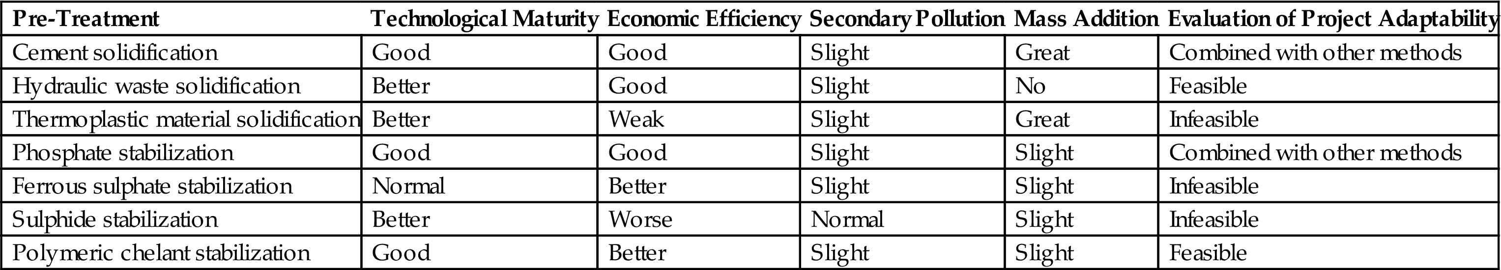
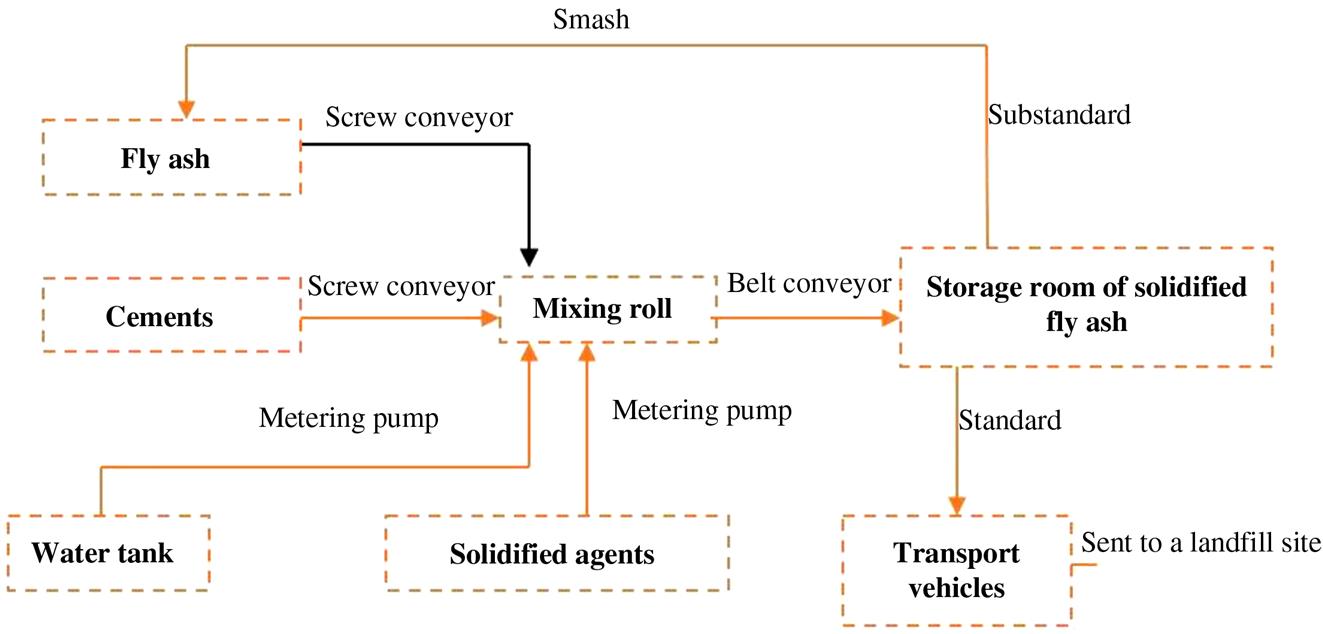
In consideration of the economy and security, solidification with cement and chemicals was used in most of the Chinese municipal solid waste incineration plant, as landfill became the last procedure. Chemicals like organic chelating agents have proven to be the best choice, with respect to its performance or stability. At present, organic chelating agents are used on a large scale in countries with a dreadfully scarce land and performed well as expected, making the high price of these agents negligible. A combination of cement and organic chelating agents was established and pre-treatment flowchart is illustrated in Figs. 9.3 and 9.4. For example, TOSOH Corporation in Japan has more than 200 such fly ash pre-treatment plants or waste incineration power plant which treat fly ash directly in this way, and a variety of environmental indicators superior to the existing standards. As a result, this method is recommended in this project.

Because of the uncertainty of leaching toxicity of fly ash, except the use of polymer organic chemical stabilization, any other single stabilization or solidification method cannot well meet the requirements of the above three principles. Therefore, the method should be selected based on the results of the leaching toxicity of fly ash, through a test selection of one or the combination of the two techniques not only ensuring safety but also saving the capacity and costs possible.
Hence, organic polymer chelating agent stabilization treatment plus cement solidification process was used in this project for the stabilization and solidification of fly ash.
9.3.2 Process of Pretreatment
In order to guarantee the security of stabilization process, some details should be focused on to meet the requirements of the whole system. For example, the storage bunkers of fly ash and cement must have cleaning hole as well as observation window which almost can bear at least 150°C. The delivery pipelines should be made from Q235A steel and some observation windows should be installed as well. All materials contact with chelating agents will be non-toxic and corrosion-resistant, as the poly ethylene (PE) is available.
9.3.3 Technical Parameters
The process of pretreatment of fly ash is shown in Fig. 9.3. This project involved two processing lines working for 16 h every day, and each of processing lines had a disposal of 75 t/d of fly ash. Other technical parameters are shown in Table 9.10.
Table 9.10
Technical Parameters of Solidification System for Fly Ash
| No. | Parameters | Value |
| 1 | Density of fly ash | 0.4–0.65 t/m3 |
| 2 | Angle of repose | 60° |
| 3 | Daily run time | 8 h |
| 4 | Capacity of the system | 50 t/d (6.25 t/h) |
| 5 | Capacity of every mixing roll | 25 t/d (3.125 t/h) |
| 6 | Power of mixing roll | 45 kW |
| 7 | Storage capacity of fly ash | 50 t each |
| 8 | Storage capacity of cement | 17.5 t each |
| 9 | Storage capacity of chelating agents (50% volume concentration) | 21 t each |
| 10 | Consumption of cements | 8 t/d, 0.625 t/h (10% volume of addition) |
| 11 | Consumption of chelating agents | 1.5 t/d, 0.188 t/h (3% volume of addition) |
| 12 | Consumption of water | 15 t/d, 1.875 t/h (30% volume of addition) |
| 13 | Curing time of conveyor | 30 min |
| 14 | Total capacity of solar power | 204 kW |
9.3.4 Overall Process Description
Through the disk feeder under the fly ash storage bin, the fly ash is quantitatively supplied via the mixing screw conveyor. At the same time, the cement is provided quantitatively via disk feeder under the cement storage bin by the mixed screw conveyor. The disk feeder under the cement storage bin has a delayed start regulating function, so as to adjust and make the fly ash and cement mixed quantitatively.
The mixture of fly ash and cement are mixed preliminarily by the screw conveyor, and then conveyed to mixer inlet where there is a material detector and then mix the materials. When the mixtures reach to the mixer, a chelating agent mixture solution is injected into it with a 1.5 MPa pressure.
There is a water automatic adjustment device in the mixer to adjust the amount of chelating agent and water by real-time monitoring of material characteristics.
The fly ash, chelating agent and cement are mixed in the mixer, the heavy metals in the fly ash can take complexation reactions with chelating agent and generate insoluble substance to reach stabilization.
The material which is mixed in the mixing mill drops in curing conveyor, after 30 min, the initial solidification of cement is completed, and then drops into the vehicle. The fly ash is transported by vehicle to the corresponding stack, which is in the factory outlet store to stack and maintenance, while takes 10 groups of test samples for laboratory analysis. After three days analysis, when these 10 groups are qualified, the solidified wastes are transported by vehicles to landfill site for dumping. If any of these groups’ leaching toxicity are monitored unqualified, the processing materials would be back to the mixer for reprocessing. The process flow is shown in Fig. 9.4.
9.4 Requirements of the System
1. Cleaning holes are arranged on the fly ash storage bin and cement storage bin, the Plexiglass of the observation hole which is in the cleaning hole need a design of 150° tolerance. The temperature of the surface of fly ash storage insulation layer should not be higher than 50°C.
2. The observation window is arranged on the system pipeline of fly ash and cement processing to observe whether there is material passing through, the tolerance of the Plexiglass of the observation window should be more than 150°C and the observation window should be movable for cleaning and the material of the pipeline is Q235A.
3. The nozzle, valve, instrument which are using for the delivery of chelating agent and chelating agent mixture in the system are made from PE or equivalent alkali corrosion resistance material.
4. The materials which contact the fly ash in the system will be specially processed, and the parts which are easy to wear can be replaced conveniently.
5. The value of any equipment noise (1 m away from the noise source) should be less than 85 dB.
6. The cable of the control system should be in accordance with the anti-jamming and anti-corrosion requirements of the national standards and regulations related.
7. The electrical equipment should be in accordance with the requirements of the national standards and regulations related, protection grade cannot be less than IP54.
9.4.1 Fly Ash Feeding System
This system is mainly composed of fly ash storage bin, roof scrubber, discharging device, electric heat tracing and other accessories. The chamber body with a circular design welded with an entire steel plate, and the angle of conical on the bin body is 60°C. The support of the fly ash storage silo is welded by steel and the welding stress is eliminated. The structure of the support is convenient for field work. Moreover, the handle’s height of the stair and platform is no less than 1100 mm.
For the sake of stability of the whole system, the storage of the ash tank is set at 50 t/d (2 days capacity for each line). At the same time, in order to prevent the fly ash from agglomeration due to moisture absorption, fly ash storage bin is arranged on the electric heating system, making the warming temperature difference stayed at 100°C. Two sets of simple bridge crack device are designed to prevent the fly ash from bridging, one is compressed air bridge crack which is commonly used, and another is manual vibration. Because the fly ash is easy to absorb moisture and caked, once the cake is not so hard and it can be broken by the compressed air, or it will be broken by manual vibration. Fig. 9.5 shows the method of manual vibration for fly ash cake due to moisture absorption.

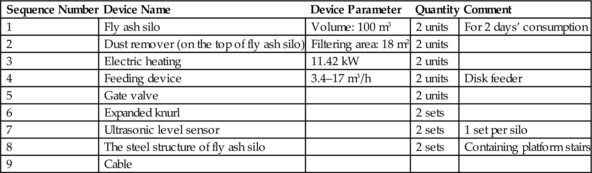
The feeding process of fly ash is as follows. The fly ash sent by the tank in the incineration plant blow into the fly ash storage by compressed air. The capacity of 18 m2 bag-type dust remover is arranged on the top of the storage. When the fly ash is sent to the storage, the resultant gas which is separated by the dust remover is discharged into the atmosphere. The temperature of fly ash which will get into the storage may be 20°C of room temperature, and should increase to 100°C in the storage by electric heating to prevent the fly ash from agglomeration. The top platform of the storage is constructed with steel rather than grid so that the scattered fly ash can be cleaned and then sent to the storage to prevent the fly ash diffusion into the air (Table 9.11). The discharge of fly ash is metered feeding by disk feeder that can effectively prevent the jam phenomenon of the screw feeder. Fly ash storage is provided with ultrasonic material position detector to detect material level, as the signal of material level is transmission to the simulation screen in the control room by automatic control system. The calculation results are given in Tables 9.12–9.15.
Table 9.11
Calculation Sheet of the Fly Ash Silo
| Function | Storing Fly Ash |
| Structure | Upright cylinder with cone in the bottom |
| Quantity | 2 units |
| Main material | Q235A |
| Operating mode | Serial fashion |
| Operating temperature | 120°C (Max) |
Capacity calculation: Storage: 50 t/unit (for 2 days’ consumption). Stacking density of fly ash: 0.4–0.6 t/m3 (choosing 0.5 t/m3). Volume: 50 t/0.5 t/m3=100 m3. Equipment size (diameter × height): 4.5 m × 10 m.
Table 9.12
Calculation Sheet of the Roof Scrubber
| Function | Separating Fly Ashes From Gas |
| Structure | Upright cylinder (provided with a motor, cleaning dust through mechanical vibrations) |
| Quantity | 2 units |
| Filtering area | 18 m2 |
| Filtration material | Polyester |
| Temperature | ≤120°C |
| Purification efficiency | 99.5% |
| Motor power | 1.5 kW |
Table 9.13
Calculation Sheet of the Electric Heating System
| Function | To Keep Fly Ash from Lumping |
| Heating form | Electrical heating |
| Insulation material | Fiberglass |
| Quantity | 2 units |
| Control methods | Manual operation/automatical operation |
| Operating mode | Serial fashion |
| Temperature | 120°C (max) |
Power calculation: Temperature: 20°C. Heating temperature difference: 100°C. Insulation material: fiberglass (50 mm). Total heat consumption: 1.8 × QB × S = 1.8 × 78.77 × 93.61 = 13.27 kW.
Table 9.14
Calculation Sheet of the Feeding Device
| Function | Disk Feeder |
| Quantity | 2 units |
| Driving forms | Frequency control |
| Discharging capacity | 3.4–17 m3/h (Design capacity: 5.2 m3/h) |
| Disk diameter | 1000 mm |
| Motor power | 3 kW |
Table 9.15
List of Fly Ash Feeding Devices
| Sequence Number | Device Name | Device Parameter | Quantity | Comment |
| 1 | Fly ash silo | Volume: 100 m3 | 2 units | For 2 days’ consumption |
| 2 | Dust remover (on the top of fly ash silo) | Filtering area: 18 m2 | 2 units | |
| 3 | Electric heating | 11.42 kW | 2 units | |
| 4 | Feeding device | 3.4–17 m3/h | 2 units | Disk feeder |
| 5 | Gate valve | 2 units | ||
| 6 | Expanded knurl | 2 sets | ||
| 7 | Ultrasonic level sensor | 2 sets | 1 set per silo | |
| 8 | The steel structure of fly ash silo | 2 sets | Containing platform stairs | |
| 9 | Cable |
9.4.2 Cement Feeding System
The cement feed system includes cement storage bin, dust collector, discharge device, mixing conveyor, electric hoist and other devices.
As the same with the fly ash storage bunker, the entire bunker is typically rounded design with the cone angle of 60°. For the convenience of maintenance and repairing, a platform is set to walk between the cement storage bin and fly ash storage bin. Details is implemented according to the “steel and aluminum vertical cylindrical feed bunker design specifications” (SH3078-96). The ccalculation sheet of device parameters is provided in Tables 9.16–9.20.
Table 9.16
Calculation Sheet of the Cement Silo
| Function | Storing Cement |
| Structure | Upright cylinder with cone in the bottom |
| Quantity | 2 units |
| Main material | Q235A |
| Operating mode | Serial fashion |
Table 9.17
Calculation Sheet of the Roof Scrubber for Cement
| Function | Separating Cement From Gas |
| Structure | Upright cylinder |
| Quantity | 2 units |
| Filtering area | 9 m2 |
| Filtration material | Polyester |
| Temperature | Room temperature |
| Purification efficiency | 99.5% |
| Motor power | 0.8 kW |
Table 9.18
Calculation Sheet of the Cement Feeder
| Function | Disk Feeder |
| Quantity | 2 units |
| Driving forms | Frequency control |
| Discharging capacity | 0.15–1.05 m3/h (design capacity: 0.24 m3/h) |
| Disk diameter | 400 mm |
| Motor power | 1 kW |
Table 9.19
Calculation Sheet of the Conveyor for Cement
| Function | Blending Transportation Between Fly Ash and Cement |
| Type | Screw conveyor |
| Quantity | 2 units |
| Transportation capacity | 4 t/h (max: 12 t/h) |
| Transportation length | 5 m |
| Motor power | 1.1 kW |
| Control methods | Manual operation/automatical operation |
| Operating mode | Serial fashion |
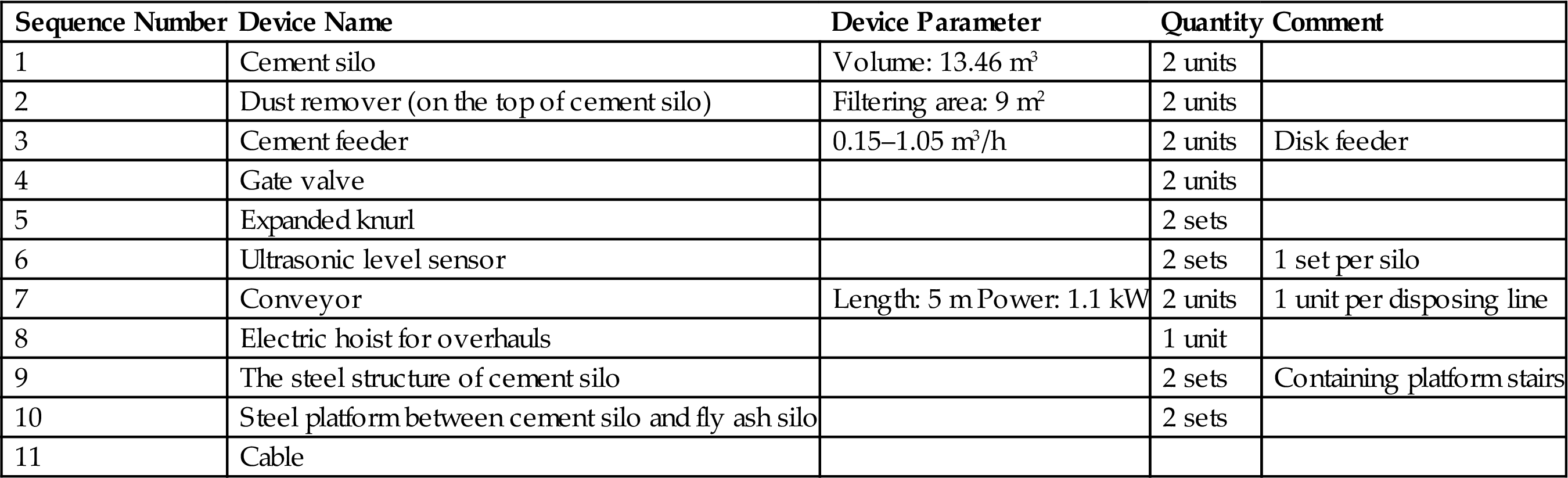
Table 9.20
List of Cement Feeding Devices
| Sequence Number | Device Name | Device Parameter | Quantity | Comment |
| 1 | Cement silo | Volume: 13.46 m3 | 2 units | |
| 2 | Dust remover (on the top of cement silo) | Filtering area: 9 m2 | 2 units | |
| 3 | Cement feeder | 0.15–1.05 m3/h | 2 units | Disk feeder |
| 4 | Gate valve | 2 units | ||
| 5 | Expanded knurl | 2 sets | ||
| 6 | Ultrasonic level sensor | 2 sets | 1 set per silo | |
| 7 | Conveyor | Length: 5 m Power: 1.1 kW | 2 units | 1 unit per disposing line |
| 8 | Electric hoist for overhauls | 1 unit | ||
| 9 | The steel structure of cement silo | 2 sets | Containing platform stairs | |
| 10 | Steel platform between cement silo and fly ash silo | 2 sets | ||
| 11 | Cable |
9.4.3 Water and Chelating Agent Configuration System
This system consists of chelating agent storage tank, process water storage tank, mixing tank, chelating agent metering pumps, metering pump of process water, mixing metering pumps, pipes, valves, instrumentation and other components.
Process water and chelating agent configuration system are set in the whole plant project. Chelating agent and water are pumped into the mixing tank in proportion through metering pump. Mixed liquid is stirred by an agitator in the mixing vessel. After that, it is pumped by the metering pump at a pressure of 1.5 MPa into the mixing roll in which the mixed liquid is reacted with a mixture of fly ash and cement. Working process is as follows. The chelating agent in the storage tank is diluted with water to a concentration of 50%. Chelating agent is conveyed into the mixed solution tank by metering pump and process water is conveyed through a metering pump by the volume of mixing ratio 1:15 into the solution tank. Mixing solution of two liquids in the tank is mixed by the stirrer uniformly and delivered at the pressure of 1.5 Mpa by the metering pump then injected into the fly ash mixing roll. The relevant parameters are given in Tables 9.21–9.28.
Table 9.21
Process Water Standards for Chelating Agents Dilution
| Item | Value |
| pH | >4 |
| Insoluble substance (mg/L) | <5000 |
| Soluble substance (mg/L) | <10,000 |
| Chloride (in Cl− terms) (mg/L) | <3500 |
| Sulfates (in SO42− terms) (mg/L) | <2700 |
| Sulfides (in S2− terms) (mg/L) | – |
Table 9.22
Calculation Sheet of Storage Tank for Chelating Agents
| Function | Storing Chelating Agents |
| Structure | Upright cylinder |
| Quantity | 1 unit |
| Main material | PE |
| Solution pH value | 9–12 |
| Operating mode | Serial fashion |
| Temperature | Room temperature |
Capacity calculation: Storage: 21 t/unit (for 7 days’ consumption). Solution concentration: Calculated at 50% concentration. Solution density: 1.1 t/m3. Volume: 21 t/1.1 t/m3 = 19 m3. Equipment size (diameter × height): 4 m × 1.5 m.
Table 9.23
Calculation Sheet of Storage Tank for Process Water
| Function | Storing Process Water |
| Structure | Upright cylinder |
| Quantity | 1 unit |
| Main material | PE |
| Operating mode | Serial fashion |
| Temperature | Room temperature |
Capacity calculation: Storage: 7.5 t/unit (for 1 day’s consumption). Solution density: 1.0 t/m3. Volume: 7.5 t/1.0 t/m3 = 7.5 m3. Equipment size (diameter × height): 2 m × 2.5 m.
Table 9.24
Calculation Sheet of Mixing Stirred Tank
| Function | Storing Ready-Prepared Chelating Agents Solution |
| Structure | Upright cylinder |
| Quantity | 1 unit |
| Main material | PE |
| Operating mode | Serial fashion |
| Temperature | Room temperature |
Capacity calculation: Storage: 6.56 t/unit (for 3 h consumption). Solution density: 1.0 t/m3. Volume: 6.56 t/1.0 t/m3 = 6.56 m3. Equipment size (diameter × height): 2.5 m × 1.5 m.
Table 9.25
Calculation Sheet of Metering Pump for Chelating Agents
| Function | Transporting Chelating Agents Solution with 50% Concentration |
| Structure | Diaphragm metering pump |
| Number | 2 units (one served as standby) |
| Conveyed material | Chelating agents (alkaline liquid) |
| Flow range | Flow range is around 946 L/h (design flow: 376 L/h) which is continuously adjustable |
| Pressure | 3.5 bar |
| Control methods | Manual operation/automatical operation |
| Operating mode | Intermittent operation |
| Temperature | Room temperature |
| Others | Corrosion-resistant PVDF pump head |
| Power | 3 kW |
Table 9.26
Calculation Sheet of Metering Pump for Process Water
| Function | Transporting Process Water |
| Type | Plunger metering pump |
| Quantity | 2 units (one served as standby) |
| Conveyed material | Process water |
| Flow range | Design flow: 376 L/h, continuous and adjustable |
| Pressure | 3.5 bar |
| Control methods | Manual operation/automatical operation |
| Operating mode | Intermittent operation |
| Temperature | Room temperature |
| Others | Corrosion-resistant PVDF pump head |
| Power | 5 kW |
Table 9.27
Mixing and Metering for Prepared Chelating Solution
| Function | Transporting Ready-Prepared Chelating Agents Solution |
| Type | Diaphragm metering pump |
| Quantity | 2 units (one served as standby) |
| Conveyed material | Ready-prepared chelating agents solution |
| Flow range | Design flow: 376 L/h, continuous and adjustable |
| Pressure | 1.5 MPa |
| Control methods | Manual operation/automatical operation |
| Operating mode | Serial fashion |
| Temperature | Room temperature |
| Others | Corrosion-resistant PVDF pump head |
| Power | 8 kW |
Table 9.28
The Devices for Process Water and Chelating Agents
| Sequence Number | Device Name | Device Parameter | Number |
| 1 | Storage tank for chelating agents | Material: PE Volume: 19 m3 | 1 unit |
| 2 | Storage tank for process water | Material: PE Volume: 7.5 m3 | 1 unit |
| 3 | Mixing stirred tank | Material: PE Volume: 6.56 m3 | 1 unit |
| 4 | Liquid stirrer | Stainless steel, power: 1.5 kW | 2 units |
| 5 | Liquidometer | 3 sets | |
| 6 | Valve | ||
| 7 | Cable |

9.4.4 Fly Ash Mixing Machine
The mixtures of fly ash and cement enter from the feed inlet in which a material detector is arranged. The material entering into the mixing parts of mixing machine is arranged on the spiral propulsion and the mixture is pushing into the coaxial mixing rod by the spiral propulsion for material mixing. The materials are fully mixed in the advancing process by the space between the material and the process of mixing rod.
The mixing rod is arranged along the axis for spiral arrangement, along the main axis with every 360° and layout 8 mixing rods. Then the axis is formed by 16 root mixing rods stirring combination in section. Through the machinery transmission of the gear box, the double spindle rotates with an inconstant speed, which is better for material mixing, and effectively prevent the mixer jam.
Water automatic adjustment device detector is arranged at the mixing part of the mixing machine to detect the water ration of the material, which could help control the addition of chelating agent and water, make the chelating agent mixed with material much more uniform and effectively.
At the same time, an overload protection device is arranged on the mixing machine. The pushing blade links the spindle in screw bolts, the mixing rod and spiral propulsion links the spindle in screw bolts. This connection can not only guarantee the firmness for promoting and stirring, but also convenient for the equipment repair and replacement. The replacement of spiral propulsion and mixing rod in each mixing machine can be completed in 8 h.
The material of spiral propulsion and mixing rod in the mixing machine adopts hard alloy wear resistant 1Cr15. The hardness of hard alloy should be more than 400HB. The shell materials using the whole plate model shall be steel Q235-A, thickness is more than 6 mm, sealed with heat-resistant gasket. The lining of the shell adopts hard alloy material 1Cr15, thickness is more than 6 mm, the lining and the shell is fixed by the bolt, which can be disassembled and replaced. The calculation of the bending deformation of double spindle is less than 1/1000 L (L is the length of the screw conveyor shell). The influence of the work temperature should be taken into consideration, the minimal clearance between the screw and the shell is not less than 5 mm.
This technology arranges the spiral propulsion and mixing rod on the stirring machine, mixing the materials of full uniform by the mixing rod, which make the heavy metals in the duct can be cured completely, no dust, no leakage. The typical parameters are given in Tables 9.29 and 9.30.
Table 9.29
Calculation Sheet of Fly Ash Stirring Mixer
| Function | Making Sure That Material is Mixed More Evenly |
| Structure | Double-axial agitator |
| Quantity | 2 units |
| Processing capacity (the amount of fly ash) | 3.125 t/(h·unit) |
| Main material | Q235A |
| Facility weight | 14 t/unit |
| Control methods | Manual operation/automatical operation |
| Operating mode | Serial fashion |
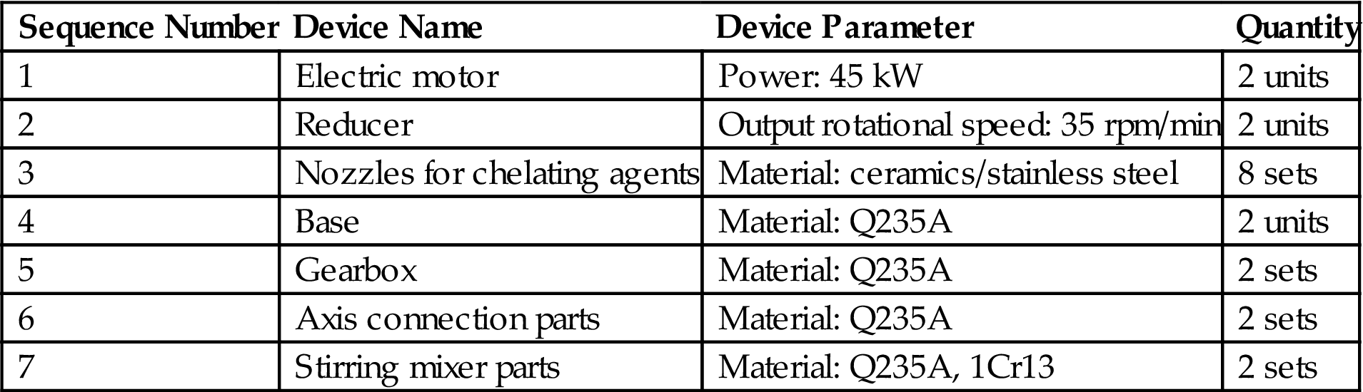
Table 9.30
List of Fly Ash Mixing Devices
| Sequence Number | Device Name | Device Parameter | Quantity |
| 1 | Electric motor | Power: 45 kW | 2 units |
| 2 | Reducer | Output rotational speed: 35 rpm/min | 2 units |
| 3 | Nozzles for chelating agents | Material: ceramics/stainless steel | 8 sets |
| 4 | Base | Material: Q235A | 2 units |
| 5 | Gearbox | Material: Q235A | 2 sets |
| 6 | Axis connection parts | Material: Q235A | 2 sets |
| 7 | Stirring mixer parts | Material: Q235A, 1Cr13 | 2 sets |
9.4.5 Maintenance of Conveying System
The stabilized fly ash through the mixing of the mixer drops onto the curing conveyor from the discharge port. The stabilized fly ash maintains 30 min in the curing conveyor so that the cement can fully be solidified, and then sent to the transport vehicle by the maintenance conveyor for maintaining in fly ash temporary storage room.
The belt conveyor is designed according to the serious impact and the shock load. The design should consider that different sizes of the condensates may drop and cause the operation difficult or even stop the operation. At the same time, the measures of removing large fly ash solidification block should be considered. The design of the maximum transmission capacity of the conveyor according to 5 times the necessary transport capacity to make sure the components of the conveyor are not damaged when under the maximum processing system.
The maximum deviation do not exceed the 5% of the bandwidth of the belt conveyor in the running time, a belt deviation adjusting device is thus set. The falling impact of the material and the affection of the belt deviation should be taken full account when designed the system.
The sweeper is arranged at the end of the belt discharge roller, non-bearing surface cleaning device should be arranged at the beginning of the tail roller and the first turnabout drum of the tensioning device. The cleaning sheet should wear and not brittle to ensure the safe and reliable.
The service life of the adhesive tape is not less than 30,000 h, other easy wear parts service life is not less than 30,000 h, the bearing service life is not less than 80,000 h, the roller service life is not less than 50,000 h when under normal service.
The internal of the roller matched with multiple labyrinth seal to prevent the dust, dirt and water from invasion. In order to make the supports, drive frame, headstock, tailstock of the belt conveyor should be manufactured with reasonable material, adequate stiffness and strength should be ensured, the weld shall be firm, beautiful appearance, uniform, and equipment shows smooth, no burr.
All the belt conveyors are arranged with sealing cover to ensure the system running in a sealed state, in order to prevent the material from blocking. The distance between the top of the sealing cover and the tape surface is not less than 500 mm, the brink of the sealing cover is fixed with the hinge which could make it easy to open. Both elevated sides of the sealing cover set with organic glass observation window and width of the window should not exceed 1.5 m.
In addition to meet the above requirements, conveyor design should also meet the relevant provisions of the “belt conveyor safety norms” (GB 14784-93), as shown in Table 9.31.
Table 9.31
| Function | Helping Cement to Initial Set |
| Type | Leather belt |
| Quantity | 1 unit |
| Conveying capacity | 6–27 t/h (design capacity: 9 t/h) |
| Conveying speed | 0.6 m/min |
| Conveying length | 19 m |
| Control methods | Manual operation/automatical operation |
| Operating mode | Serial fashion |
| Power | 4.5 kW |
9.4.6 Compressed Air System
The project deploys 2 piston type air compressors, 1 using and 1 alternate (Table 9.32).
Table 9.32
| Function | Supplying Compressed Air |
| Type | Piston air compressor |
| Quantity | 2 units (one served as standby) |
| Gas supplying capacity | 3.8 m3/min (max) |
| Gas supplying pressure | 0.7/0.8/1.0/1.2 MPa |
| Noise | 65 ± 2 dB |
| Control methods | Manual operation/automatical operation |
| Operating mode | Serial fashion |
| Power | 18 kW |
9.4.7 Electrical System
According to the process conditions of this project, power system adopts low grade of factory voltage, with all the equipment or facilities using low voltage power supply, namely 220/380 V. Power cabinet is set in low voltage auxiliary power system.
The motor control center (MCC) supplies power for the top silo dust collector, electric heat, the disk feeder, conveyor, mixer, curing conveyor and automatic control system.
Power compensation device is arranged in the system, to improve the electrical stability, ensure factor of the power above 0.9, with ABB equipment.
Reference voltage compensation (RVC) series power factor controller is a low voltage reactive power compensation controller by the company of ABB. RVC series controller with powerful function, strong anti-interference ability, can work normally in the harmonic distortion of large power grid environment, with harmonic overrun warning function.
The fire protection system is set with the special fire protection power, which is from two different 220/380 V bus bar section of the power center.
The system is provided with 1 set of UPS (un-interruptible power supply), to supply the power for the control center and the Programmable Logic Controller (PLC). A metering station is arranged in the MCC in the system to measure the power consumption of the plant. The cable in the project include: cable trays, cables along the cable trench laying, pipe laying and buried several laying methods. List of electrical machines used is provided in Table 9.33.
Table 9.33
| Item | Name | Quantity (unit/set) | Power (kW) | Needful Coefficient | Computational Complexity | ||
| Installing | Running | Installing | Running | ||||
| I | Fly Ash Feeding System | ||||||
| 1 | Dust remover (on the top of fly ash silo) | 2 | 2 | 3 | 3 | 0.7 | 2.1 |
| 2 | Electric heating | 2 | 2 | 26.54 | 26.54 | 0.7 | 18.58 |
| 3 | Disk feeder | 2 | 2 | 6 | 6 | 0.7 | 4.2 |
| 4 | Gate valve | 2 | 2 | 0.5 | 0.5 | 0.3 | 0.15 |
| 5 | Ultrasonic level sensor | 2 | 2 | 0.5 | 0.5 | 1 | 0.5 |
| 6 | Others | 1 | 1 | 0.2 | 0.2 | 0.7 | 0.14 |
| Subtotal | 36.74 | 36.74 | 25.67 | ||||
| II | Cement Feeding System | ||||||
| 1 | Dust remover (on the top of cement silo) | 2 | 2 | 1.6 | 1.6 | 0.7 | 1.12 |
| 2 | Disk feeder | 2 | 2 | 1 | 1 | 0.7 | 0.7 |
| 3 | Gate valve | 2 | 2 | 0.5 | 0.5 | 0.3 | 0.15 |
| 4 | Ultrasonic level sensor | 2 | 2 | 0.5 | 0.5 | 1 | 0.5 |
| 5 | Conveyor | 2 | 2 | 2.2 | 2.2 | 0.7 | 1.54 |
| 6 | Electric hoist for overhauls | 2 | 2 | 2 | 2 | 0.3 | 0.6 |
| 7 | Others | 1 | 1 | 0.2 | 0.2 | 0.7 | 0.14 |
| Subtotal | 8 | 8 | 4.75 | ||||
| III | Configuration System of Process Water and Chelating Agents | ||||||
| 1 | Metering pump for chelating agents | 2 | 1 | 1.1 | 0.55 | 1 | 0.55 |
| 2 | Metering pump for process water | 2 | 1 | 3 | 1.5 | 1 | 1.5 |
| 3 | Metering pump for ready-prepared chelating agents solution | 2 | 1 | 3 | 1.5 | 1 | 1.5 |
| 4 | Liquid stirrer | 2 | 2 | 3 | 3 | 1 | 3 |
| 5 | Liquidometer | 3 | 3 | 0.1 | 0.1 | 1 | 0.1 |
| 6 | Valve | 1 | 1 | 1 | 1 | 0.4 | 0.4 |
| Subtotal | 11.2 | 7.65 | 7.05 | ||||
| IV | Fly Ash Stirring Mixer | ||||||
| 1 | Fly ash stirring mixer | 2 | 2 | 90 | 90 | 0.7 | 63 |
| Subtotal | 90 | 90 | 63 | ||||
| V | Conveyor | ||||||
| 1 | Conveyor | 1 | 1 | 4.5 | 4.5 | 0.7 | 3.15 |
| Subtotal | 4.5 | 4.5 | 3.15 | ||||
| VI | Compressed Air System | ||||||
| 1 | Air compressor | 2 | 1 | 36 | 18 | 0.5 | 9 |
| Subtotal | 36 | 18 | 9 | ||||
| VII | Automatic Control System | ||||||
| 1 | Automatic control system | 1 | 1 | 1 | 1 | 0.7 | 0.7 |
| Subtotal | 1 | 1 | 0.7 | ||||
| VIII | Ventilation and Air Conditioning Systems | ||||||
| 1 | Ventilator | 8 | 8 | 4 | 4 | 0.7 | 2.8 |
| 2 | Air condition | 4 | 4 | 8 | 8 | 0.5 | 4 |
| Subtotal | 12 | 12 | 6.8 | ||||
| IX | Illumination | ||||||
| 1 | Illumination | 1 | 1 | 5 | 5 | 0.7 | 3.5 |
| Subtotal | 5 | 5 | 3.5 | ||||
| Total | 204.44 | 182.89 | 123.62 | ||||

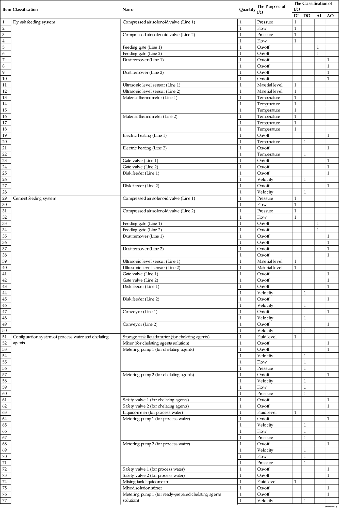
9.4.8 Automatic Control System
The independent PLC is applied to control the fly ash stabilization system, which can transfer the data to the control room. For the fly ash storage silo, cement silo, chelating agent storage tank and mixing tank, it can initiate the sound and light alarm when the material level falls below the lower level by the high, low, below low signals emitted by the ultrasonic detector and level gage.
Mixing tank agitator starts together with fly ash and cement silo unloading valve. The chelating dilution metering pump is controlled by the detectors installed on the inlet of the mixing materials (Table 9.34).
Table 9.34
Detailed List of Automatic Installations
| Item | Classification | Name | Quantity | The Purpose of I/O | The Classification of I/O | |||
| DI | DO | AI | AO | |||||
| 1 | Fly ash feeding system | Compressed air solenoid valve (Line 1) | 1 | Pressure | 1 | |||
| 2 | 1 | Flow | 1 | |||||
| 3 | Compressed air solenoid valve (Line 2) | 1 | Pressure | 1 | ||||
| 4 | 1 | Flow | 1 | |||||
| 5 | Feeding gate (Line 1) | 1 | On/off | 1 | ||||
| 6 | Feeding gate (Line 2) | 1 | On/off | 1 | ||||
| 7 | Dust remover (Line 1) | 1 | On/off | 1 | ||||
| 8 | 1 | On/off | 1 | |||||
| 9 | Dust remover (Line 2) | 1 | On/off | 1 | ||||
| 10 | 1 | On/off | 1 | |||||
| 11 | Ultrasonic level sensor (Line 1) | 1 | Material level | 1 | ||||
| 12 | Ultrasonic level sensor (Line 2) | 1 | Material level | 1 | ||||
| 13 | Material thermometer (Line 1) | 1 | Temperature | 1 | ||||
| 14 | 1 | Temperature | 1 | |||||
| 15 | 1 | Temperature | 1 | |||||
| 16 | Material thermometer (Line 2) | 1 | Temperature | 1 | ||||
| 17 | 1 | Temperature | 1 | |||||
| 18 | 1 | Temperature | 1 | |||||
| 19 | Electric heating (Line 1) | 1 | On/off | 1 | ||||
| 20 | 1 | Temperature | 1 | |||||
| 21 | Electric heating (Line 2) | 1 | On/off | 1 | ||||
| 22 | 1 | Temperature | 1 | |||||
| 23 | Gate valve (Line 1) | 1 | On/off | 1 | ||||
| 24 | Gate valve (Line 2) | 1 | On/off | 1 | ||||
| 25 | Disk feeder (Line 1) | 1 | On/off | 1 | ||||
| 26 | 1 | Velocity | 1 | |||||
| 27 | Disk feeder (Line 2) | 1 | On/off | 1 | ||||
| 28 | 1 | Velocity | 1 | |||||
| 29 | Cement feeding system | Compressed air solenoid valve (Line 1) | 1 | Pressure | 1 | |||
| 30 | 1 | Flow | 1 | |||||
| 31 | Compressed air solenoid valve (Line 2) | 1 | Pressure | 1 | ||||
| 32 | 1 | Flow | 1 | |||||
| 33 | Feeding gate (Line 1) | 1 | On/off | 1 | ||||
| 34 | Feeding gate (Line 2) | 1 | On/off | 1 | ||||
| 35 | Dust remover (Line 1) | 1 | On/off | 1 | ||||
| 36 | 1 | On/off | 1 | |||||
| 37 | Dust remover (Line 2) | 1 | On/off | 1 | ||||
| 38 | 1 | On/off | 1 | |||||
| 39 | Ultrasonic level sensor (Line 1) | 1 | Material level | 1 | ||||
| 40 | Ultrasonic level sensor (Line 2) | 1 | Material level | 1 | ||||
| 41 | Gate valve (Line 1) | 1 | On/off | 1 | ||||
| 42 | Gate valve (Line 2) | 1 | On/off | 1 | ||||
| 43 | Disk feeder (Line 1) | 1 | On/off | 1 | ||||
| 44 | 1 | Velocity | 1 | |||||
| 45 | Disk feeder (Line 2) | 1 | On/off | 1 | ||||
| 46 | 1 | Velocity | 1 | |||||
| 47 | Conveyor (Line 1) | 1 | On/off | 1 | ||||
| 48 | 1 | Velocity | 1 | |||||
| 49 | Conveyor (Line 2) | 1 | On/off | 1 | ||||
| 50 | 1 | Velocity | 1 | |||||
| 51 | Configuration system of process water and chelating agents | Storage tank liquidometer (for chelating agents) | 1 | Fluid level | 1 | |||
| 52 | Mixer (for chelating agents solution) | 1 | On/off | 1 | ||||
| 53 | Metering pump 1 (for chelating agents) | 1 | On/off | 1 | ||||
| 54 | 1 | Velocity | 1 | |||||
| 55 | 1 | Flow | 1 | |||||
| 56 | 1 | Pressure | 1 | |||||
| 57 | Metering pump 2 (for chelating agents) | 1 | On/off | 1 | ||||
| 58 | 1 | Velocity | 1 | |||||
| 59 | 1 | Flow | 1 | |||||
| 60 | 1 | Pressure | 1 | |||||
| 61 | Safety valve 1 (for chelating agents) | 1 | On/off | 1 | ||||
| 62 | Safety valve 2 (for chelating agents) | 1 | On/off | 1 | ||||
| 63 | Liquidometer (for process water) | 1 | Fluid level | 1 | ||||
| 64 | Metering pump 1 (for process water) | 1 | On/off | 1 | ||||
| 65 | 1 | Velocity | 1 | |||||
| 66 | 1 | Flow | 1 | |||||
| 67 | 1 | Pressure | 1 | |||||
| 68 | Metering pump 2 (for process water) | 1 | On/off | 1 | ||||
| 69 | 1 | Velocity | 1 | |||||
| 70 | 1 | Flow | 1 | |||||
| 71 | 1 | Pressure | 1 | |||||
| 72 | Safety valve 1 (for process water) | 1 | On/off | 1 | ||||
| 73 | Safety valve 2 (for process water) | 1 | On/off | 1 | ||||
| 74 | Mixing tank liquidometer | 1 | Fluid level | 1 | ||||
| 75 | Mixed solution stirrer | 1 | On/off | 1 | ||||
| 76 | Metering pump 1 (for ready-prepared chelating agents solution) | 1 | On/off | 1 | ||||
| 77 | 1 | Velocity | 1 | |||||
| 78 | 1 | Flow | 1 | |||||
| 79 | 1 | Pressure | 1 | |||||
| 80 | Metering pump 2 (for ready-prepared chelating agents solution) | 1 | On/off | 1 | ||||
| 81 | 1 | Velocity | 1 | |||||
| 82 | 1 | Flow | 1 | |||||
| 83 | 1 | Pressure | 1 | |||||
| 84 | Safety valve 1 (for ready-prepared chelating agents solution) | 1 | On/off | 1 | ||||
| 85 | Safety valve 1 (for ready-prepared chelating agents solution) | 1 | On/off | 1 | ||||
| 86 | Fly ash stirring mixer | Fly ash stirring mixer | 1 | On/off | 1 | |||
| 87 | Material detector | 1 | On/off | 1 | ||||
| 88 | Conveyor | Conveyor | 1 | On/off | 1 | |||
| 89 | 1 | Velocity | 1 | |||||
| 90 | Cleaner | 1 | On/off | 1 | ||||
| 91 | Compressed air system | Air compressor 1 | 1 | On/off | 1 | |||
| 92 | Air compressor 2 | 1 | On/off | 1 | ||||
| 93 | Safety valve of air compressor 1 | 1 | On/off | 1 | ||||
| 94 | Safety valve of air compressor 2 | 1 | On/off | 1 | ||||
| 95 | Automatic control system | PLC | 1 | On/off | 1 | |||
| 96 | Relay | 1 | On/off | 1 | ||||
| 97 | UPS | 1 | On/off | 1 | ||||
| Total | 97 | 21 | 27 | 4 | 45 | |||

I/O, input/output; DI, digital Input; DO, digital out; AI, analog in; AO, analog out.
9.4.9 Ventilation and Air Conditioning Systems
Ventilation design includes pretreatment plant ventilation and air conditioning, building ventilation and air conditioning. In order to guarantee the air circulation in the workshop, the ventilation frequencies are 4 times per hours, with six fiberglass oblique flow fan. The total exhaust volume is 9088 m3/h. For laboratory air circulation, the ventilation frequencies are 4 times per hours, with two fiberglass oblique flow fan, and the total exhaust volume of 1500 m3/h.
9.4.10 Lighting System and Fire Protection System
The factory installs normal lighting, emergency lighting, and interval lighting.
The factory installs fire prevention facilities and sets an outdoor fire hydrant and a special fire pump. A water tower is set to supply water for the whole plant for production and fire emergency requirements. The height of the tower is 22 m, the highest in the plant. Dry powder extinguishers are arranged in the office, control room, power control center and main plant.
9.4.11 Laboratory Analysis and Equipment Standards
Laboratory monitoring analysis is one of important tasks in the project. It should have the ability to detect all the heavy metals such as Hg, Cu, Pb, Ni, and Zn. The laboratory is divided into instruments chambers arranged with atomic absorption, atomic fluorescence spectrometer, etc.), balance room, heating room, sample preparation and a small test chamber for grinder, sample storage room, pre-treatment of heavy metal chamber and analysis room, as given in Table 9.35. The laboratory area is approximately 120 m2.
Table 9.35
Analysis and Test Instruments and Standards of Instruments
| Items | Names | Specifications | Units | Quantities | Standards |
| 1 | Atomic fluorescence spectrophotometer | Unit | 1 | JJD 1003 | |
| 2 | Atomic absorption spectrophotometer | Wave length: 190–860 nm | Unit | 1 | JJG 694 |
| 3 | Ultraviolet and visible spectrophotometer | Unit | 1 | JJD 1002 | |
| 4 | Flip concussion instrument | Unit | 1 | ||
| 5 | Pulverizer | Unit | 1 | ||
| 6 | High-temperature box resistance furnace | Rated power: 1.5–2.0 kW | Unit | 1 | |
| 7 | Photoelectric analytical balance | 0–200 g, 0.1 mg | Unit | 1 | |
| 8 | Analytical balance | 500 g/1 g | Unit | 1 | |
| 9 | Distilled water generator | Volume: 75 L/d | Unit | 1 | |
| 10 | Microwave digestion device | Unit | 1 | ||
| 11 | Electromagnetic stirrer | Rotate speed: 100–1000 r/min | Unit | 1 | |
| 12 | Acidimeter | pH: 0–14 | Unit | 2 | |
| 13 | Thermostat water bath | 20–30 L | Unit | 1 | |
| 14 | Hot plate | Ceramics 180 × 180 mm | Unit | 2 | |
| 15 | Vibrating screen | Unit | 1 | ||
| 16 | Waste water sampling apparatus | 10–990 mL | Unit | 1 | |
| 17 | Gas chromatograph | GC102M | Unit | 1 | |
| 18 | Conductivity meter | EC215 | Unit | 1 |

9.5 Parameters of Stabilization/Curing Process (Mass Balance)
The solidification/stabilization efficiency is related to the leaching toxicity of initial fly ash and its stabilized product. In general, a higher content of heavy metal in the fly ash will lead to higher dosage of stabilizers and cement. The actual dosages should be decided on lab test.
In most cases, the solidification/stabilization ratio can be set as fly ash: cement: water: stabilizers = 1: 0.1–0.3: 0.30: 0.01–0.03 in weight basis. The stabilizers may be organic P or organic S chelating agents, which are commercially available.
As a result, the total stabilized product of fly ash in this project is about 71.0 t/d, with a density 1.25–1.5 t/m3, i.e., 56.8 m3/d. The working hours are 7920 h, namely 330 days, leading to a treatment capacity of 18,500 m3. 25 years of service is designed and the total capacity is 567,000 m3.
According to the relevant regulations, the stabilized fly ash should be sent to the hazardous waste landfill for final disposal, when meets the following conditions, i.e., the moisture below 30%, the content of dioxins lower than 3 μg TEQ/kg, and leaching toxicity below the regulated values.
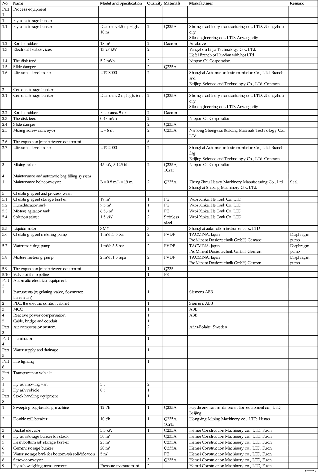
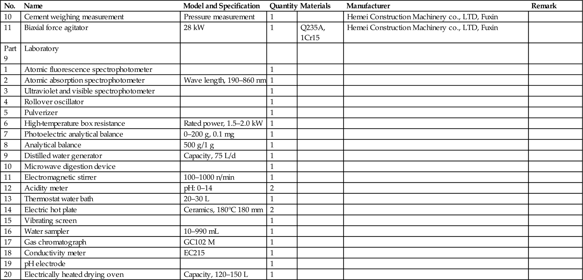
The equipment used for the fly ash stabilization and solidification is listed in Table 9.36.
Table 9.36
List of Equipment for Fly Ash Stabilization and Solidification
| No. | Name | Model and Specification | Quantity | Materials | Manufacturer | Remark |
| Part 1 | Process equipment | |||||
| 1 | Fly ash storage bunker | |||||
| 1.1 | Fly ash storage bunker | Diameter, 4.5 m; High, 10 m | 2 | Q235A | Strong machinery manufacturing co., LTD, Zhengzhou city Silo engineering co., LTD, Anyang city |
|
| 1.2 | Roof scrubber | 18 m2 | 2 | Dacron | As above | |
| 1.3 | Electrical heat devices | 13.27 kW | 2 | Yangzhou Li Jia Technology Co., LTd. Hefei Branch of Huadian with hot LTd. |
||
| 1.4 | The disk feed | 5.2 m3/h | 2 | Nippon Oil Corporation | ||
| 1.5 | Slide damper | 2 | Q235A | |||
| 1.6 | Ultrasonic level-meter | UTG8000 | 2 | Shanghai Automation Instrumentation Co., LTd. Branch and Beijing Science and Technology Co., LTd. Conason |
||
| 2 | Cement storage bunker | |||||
| 2.1 | Cement storage bunker | Diameter, 2 m; high, 6 m | 2 | Q235A | Strong machinery manufacturing co., LTD, Zhengzhou city Silo engineering co., LTD, Anyang city |
|
| 2.2 | Roof scrubber | Filter area, 9 m2 | 2 | Dacron | ||
| 2.3 | The disk feed | 0.48 m3/h | 2 | Nippon Oil Corporation | ||
| 2.4 | Slide damper | 2 | Q235A | |||
| 2.5 | Mixing screw conveyor | L = 6 m | 2 | Q235A | Nantong Sheng-hui Building Materials Technology Co., LTd. | |
| 2.6 | The expansion joint between equipment | 6 | ||||
| 2.7 | Ultrasonic level-meter | UTG2000 | 2 | Shanghai Automation Instrumentation Co., LTd. Branch flag Beijing Science and Technology Co., LTd. Conason |
||
| 3 | Mixing roller | 45 kW, 3.125 t/h | 2 | Q235A, 1Cr15 | Nippon Oil Corporation | |
| 4 | Maintenance and automatic bag filling system | |||||
| 1 | Maintenance belt conveyor | B = 0.8 m L = 19 m | 2 | Q235A | ZhengZhou Heavy Machinery Manufacturing Co., Ltd Shanghai Shibang Machinery Co., LTd. |
Seal |
| 5 | Chelating agent and process water | |||||
| 5.1 | Chelating agent storage bunker | 19 m3 | 1 | PE | Wuxi Xinkai He Tank Co. LTD | |
| 5.2 | Humidification sink | 7.5 m3 | 1 | PE | Wuxi Xinkai He Tank Co. LTD | |
| 5.3 | Mixture agitation tank | 6.56 m3 | 1 | PE | Wuxi Xinkai He Tank Co. LTD | |
| 5.4 | Solution stirrer | 1.5 kW | 2 | Stainless steel | Wuxi Xinkai He Tank Co. LTD | |
| 5.5 | Liquidometer | SMY | 3 | Shanghai automation instrument co., LTD | ||
| 5.6 | Chelating agent metering pump | 1 m3/h 3.5 bar | 2 | PVDF | TACMINA, Japan ProMinent Dosiertechnik GmbH, Gemane |
Diaphragm pump |
| 5.7 | Water metering pump | 1 m3/h 3.5 bar | 2 | PVDF | TACMINA, Japan ProMinent Dosiertechnik GmbH, German |
Diaphragm pump |
| 5.8 | Mixture metering pump | 2 m3/h 1.5 mpa | 2 | PVDF | TACMINA, Japan ProMinent Dosiertechnik GmbH, German |
Diaphragm pump |
| 5.9 | The expansion joint between equipment | 1 | Q235 | |||
| 5.10 | Valve of the pipeline | 1 | PE | |||
| Part 2 | Automatic electrical equipment | |||||
| 1 | Instruments (regulating valve, flowmeter, transmitter) | 1 | Siemens ABB | |||
| 2 | PLC, the electric control cabinet | 1 | Siemens ABB | |||
| 3 | MCC | 1 | ABB | |||
| 4 | Reactive power compensation | 1 | ABB | |||
| 5 | Cable, bridge and conduit | 1 | ||||
| Part 3 | Air compression system | 2 | Atlas-Bolaite, Sweden | |||
| Part 4 | Illumination | 1 | ||||
| Part 5 | Water supply and drainage | 1 | ||||
| Part 6 | Fire fighting | 1 | ||||
| Part 7 | Transportation vehicle | |||||
| 1 | Fly ash moving van | 5 t | 2 | |||
| 2 | Fly ash vehicle | 8 t | 1 | |||
| Part 8 | Stock handling equipment | 1 | ||||
| 1 | Sweeping bag-breaking machine | 12 t/h | 1 | Q235A | Haydn environmental protection equipment co., LTD, Beijing | |
| 2 | Double mill breaker | 10 t/h | 1 | Q235A, 1Cr15 | Hongxing Mining Machinery co., LTD, Henan | |
| 3 | Bucket elevator | 5.5 kW | 1 | Q235A | Hemei Construction Machinery co., LTD, Fuxin | |
| 4 | Fly ash storage bunker for stock | 50 m3 | Q235A | Hemei Construction Machinery co., LTD, Fuxin | ||
| 5 | Flesh bottom ash storage bunker | 25 m3 | Q235A | Hemei Construction Machinery co., LTD, Fuxin | ||
| 6 | Cement storage bunker | 20 m3 | Q235A | Hemei Construction Machinery co., LTD, Fuxin | ||
| 7 | Water storage bank for bottom ash solidification | 5 m2 | PE | Hemei Construction Machinery co., LTD, Fuxin | ||
| 8 | Screw conveyor | 3 | Q235A | Hemei Construction Machinery co., LTD, Fuxin | ||
| 9 | Fly ash weighing measurement | Pressure measurement | 2 | Hemei Construction Machinery co., LTD, Fuxin | ||
| 10 | Cement weighing measurement | Pressure measurement | 1 | Hemei Construction Machinery co., LTD, Fuxin | ||
| 11 | Biaxial force agitator | 28 kW | 1 | Q235A, 1Cr15 | Hemei Construction Machinery co., LTD, Fuxin | |
| Part 9 | Laboratory | |||||
| 1 | Atomic fluorescence spectrophotometer | 1 | ||||
| 2 | Atomic absorption spectrophotometer | Wave length, 190–860 nm | 1 | |||
| 3 | Ultraviolet and visible spectrophotometer | 1 | ||||
| 4 | Rollover oscillator | 1 | ||||
| 5 | Pulverizer | 1 | ||||
| 6 | High-temperature box resistance | Rated power, 1.5–2.0 kW | 1 | |||
| 7 | Photoelectric analytical balance | 0–200 g, 0.1 mg | 1 | |||
| 8 | Analytical balance | 500 g/1 g | 1 | |||
| 9 | Distilled water generator | Capacity, 75 L/d | 1 | |||
| 10 | Microwave digestion device | 1 | ||||
| 11 | Electromagnetic stirrer | 100–1000 n/min | 1 | |||
| 12 | Acidity meter | pH: 0–14 | 2 | |||
| 13 | Thermostat water bath | 20–30 L | 1 | |||
| 14 | Electric hot plate | Ceramics, 180°C 180 mm | 2 | |||
| 15 | Vibrating screen | 1 | ||||
| 16 | Water sampler | 10–990 mL | 1 | |||
| 17 | Gas chromatograph | GC102 M | 1 | |||
| 18 | Conductivity meter | EC215 | 1 | |||
| 19 | pH electrode | 1 | ||||
| 20 | Electrically heated drying oven | Capacity, 120–150 L | 1 |
9.6 Bill of Quantities and Environmental Protection, Health and Safety Measures
The consumption of steels, cement and wood are respectively 12.9 t, 183.87 t and 34.5 m3 (Tables 9.36 and 9.37).
Table 9.37
Bill of Civil Engineering Quantity
| No. | Name | Floorage |
| 1 | Pretreatment-workshop | 2031 m2 |
| 2 | Dormitory and cafeteria | 216 m2 |
| 3 | Discharge storage area | 480 m2 |
| 4 | Logistics area | 16 m2 |
| 5 | Action area | 16 m2 |
| 6 | Water tower | 20 m2 |
Effects of hazardous waste on ambient environment exist in the process of collecting, transporting, treating and disposing. This project is an environmental protection project aimed to control the contamination of hazardous waste, to prevent secondary contamination of hazardous waste mainly in aspects of water, air, sound.
There is no wastewater generation during production process in this project. According to the equilibrium of water, wastewater in this project mainly comes from domestic water and road washing water consumption, which can be recycled for the fly ash solidification process.
Corrosion-resistant imported materials and equipment are used to build the crucial part of production workshops. Cementitious Capillary Crystalline Waterproofing Materials is chosen to build the pretreatment ground for anti-seepage. Accident pool for collecting washing water and leaking liquid is designed, and the wastewater in accident pool will be pumped to process water using for pre-treatment.
The facilities fugitive dust generation is fully airtight. Two bag filters with a filtration area of 18 m2 and 9 m2 are set in the fly ash storage and cement storage, respectively. Collection efficiency of both bag filters can reach 99%. To prevent bag burst caused by high pressure difference, mechanical vibration device is added to the bag filters.
All equipment used is designed with low noise level (Table 9.38). For example, noise value at a distance of 1 m from an Atlas-Bolaite air compressor is only 65 ± 2 decibels which is far below the restriction of 85 decibels and shows a better performance than other air compressor in conventional treatment plant. Factory boundary noise should meet the relevant standard.
Table 9.38
Noise Sources and Control Methods
| Noise Source | Control Methods |
| Axial flow fan | Installing sound insulation boxes and exhaust muffler |
| Water pump, etc. | Installing pump vibration insolation equipment and sound enclosure |
| Reduction gear | Installing sound enclosure |
| Rotating equipment | Supplementing and replacing lubricating oil regularly |
Domestic garbage will be collected in the plant and stored to a certain amount before being transported to waste incineration power plant for disposal.
2. Monitoring of fly ash pretreatment
Laboratory in factory will be in charge of the monitoring of indexes before and after fly ash treatment. The testing and monitoring of dioxins and other indexes in fly ash will be entrusted to the qualified specialized agency.
3. Safety and hygiene
Hazardous waste is transferred from generating source to centralized disposal site for centralized disposal and security landfill ultimately. If there is improper administration in transporting process, the contamination may spread and pose a threat to human health and public security. Thus, necessary control methods must be taken so that the transporting process can be under supervision, in line with the requirements of environmental protection and conducive to contamination prevention of hazardous waste. From the experience of other countries, the main control method of hazardous waste transporting process is the transfer registered system.
As for storage, comprehensive utilization and treatment facilities, safety assurance is the primary responsibility. Safety systems should be established and improved according to a series of safety regulations issued by the State Council, provincial and municipal governments, ensuring legitimacy of safety work.
In order to ensure the safe running of fly ash pretreatment plant, distribution of safety work goals and responsibilities should be specific. Rules of reward and punishment should be kept strictly. Encouragement and reward should be given to people who find and solve serious potential fire danger in time while punishment, even administrative and criminal liability, should be executed to people who violate safety system according to relevant regulations.
Once contamination accident of hazardous waste happens, it is difficult and complicated to control, mitigating or eliminate the contamination hazard. Thus, importance should be attached to prevention work of hazardous waste contamination accidents to nip in the bud.
Preventive measures include establishing sound regulation system and organization system of accident prevention, making contingency plans and measures, preparing equipment required to control, mitigate and eliminate the contamination. The main principle is that operation staff should complete work according to regulations. Meanwhile, operation staff should recognize that contamination accidents may occur at any time and prevent all kinds of potential danger actively to eliminate danger in the bud.
Specific prevention measures should be made according to properties, quantity and treating methods of hazardous waste to be treated. Regulation system and organization system of accident prevention must be confirmed and obeyed strictly before fly ash pretreatment plant starts to run. In addition, department in charge should organize specialists to do compilation.
Appropriate action taken in the very initial few seconds can often stop the occurrence of contamination in hazardous waste contamination accidents. In the initial stage, proper measures can prevent accident scale from expanding. Therefore, making a detailed contingency plan is of great necessity in order to minimize the contamination. It can include: (1) calling the police; (2) establishing command center; (3) organizing rescue team; (4) situation assessment and accident classification; (5) establishing warning area; (6) emergency evacuation; (7) first-aid on site.
4. Project construction and operation management system
The project company will develop and implement a management system of occupational health and safety according to Occupational health and safety management system—Requirements (GB/T28001).
Goals of occupational health and safety are avoiding accidents, preventing harm to human health and environment, making first-class administration performance of occupational health and safety.
Occupational health and safety management system is running in a line management way, in accordance with management system of the project company. Departmental duties in occupational health and safety management system should be assigned clearly.
Regulations, systems or procedures should be made and improved continuously in management activities according to the requirements of actual control in order to ensure all the activities, which need to be controlled in occupational health and safety system and prevent accidents from occurring.
Operation standard should be stipulated in relevant regulations, systems and procedures. Operability of all the procedures should be ensured. In order to improve environmental performance of the company in aspects of activities, products and service, reduce environmental pollution and eliminate potential safety hazard radically, operation control procedures are set up in following aspects:
a. Control procedure of inconformity, correction and prevention measures
b. Control procedure of accident investigation, handling and report
c. Control procedure of safety signs use and management
d. Regulations of hazardous chemical management
e. Regulations of labor protection appliance management
f. Regulations of occupational disease management
g. Regulations of machinery injury operation management
h. Regulations of hazardous article (oils and chemicals) management
i. Regulations of safety facilities management
j. Regulations of outside personnel and vehicles management
k. Control procedure of environment, occupational health and safety operation
l. Management procedure of exerting influence on interested parties
5. Performance measurement and monitoring of occupational health and safety
The project company will establish and keep the Control procedure of supervision and measurements for occupational health and safety in order to keep monitoring activities relevant to important environmental factors or major risk factors and to make assessment by analyzing monitoring results.
6. Conformity evaluation of occupational health and safety
The project company will establish and keep Control procedure of laws, regulations and other requirements. Conformity evaluation will be made to realize the company promise, obeying relevant laws, regulations and other requirements.
7. Accident, incident, inconformity, correction and prevention measures
Control procedure of inconformity, correction and prevention measures, aiming at investigation, handling and measures of accidents, incidents and inconformity, will be established and kept, which will keep work of investigation, handling and report under standard procedures and make correction, prevention measures scientific, practical and efficient.
8. Records and records management
Control procedure of records will be established and kept. Relevant departments should strictly control the timeliness, veracity, authenticity and integrality of occupational health and safety management records to confirm that engineering activities of occupational health and safety meet the requirements and operation of system is effective.
a. Audit of occupational health and safety management
Control procedure of internal audit will be made, implemented and kept to examine whether the management system of occupational health and safety meets the requirements in GB/T28001.
b. Assessment of occupational health and safety management
Management assessment procedure will be made and kept to ensure the validity, adequacy and continuing suitability of occupational health and safety management system.
9.7 Security Landfill for Stabilized Hazardous Wastes
Security (or dedicated or safe) landfill should be constructed for the final disposal of stabilized hazardous wastes. The landfill can be built as that used for municipal solid wastes. It should be the least requirements for sanitary landfill, such as single 1.5 mm HDPE layer with draining system for underground water below HDPE. Sorted clay should be spread over the lining system before the waste is placed to avoid puncture of HDPE film by the wastes.
Though the stabilized wastes can be placed in a sanitary landfill, the wastes should be disposed of in a separate cell, without mixing with municipal solid waste. It is strongly recommended that the sanitary landfill for the stabilized wastes must be constructed independently.