Servers from first-tier vendors have built-in component redundancy, owing to multiple CPUs, network cards, power supplies, and so on. This means that they can last for years without failure. Your storage systems can be configured to protect your data against single or even multiple simultaneous disk failures. You can expect a server configured such as this to give reliable service for a long time, but you only have a single server. If it does fail, you’ve lost your data, your virtual environment, or whatever application the server is running. More important, your users have lost access to their applications, and your organization may be losing revenue. Losing a server running a single application is bad. Losing the server that hosts a number of virtual machines (VMs) could be catastrophic for your organization.
Operating system (OS) patching is an unavoidable requirement. A machine often has to be rebooted after patching. If the machine is a Hyper-V host, this means that all VMs on the host have to be restarted, leading to downtime that could be unacceptable to your organization.
The answer is to configure the systems for high availability (HA). This involves configuring two or more physical servers to work together, so that in the event of one failing, the workload is automatically migrated to another machine in the group. In this chapter, we’re looking at configuring Hyper-V hosts (physical machines in your environment) to work together to provide an HA environment for your VMs.
DEFINING HIGH AVAILABILITY
High availability refers to a system being continuously operational, or available, for a long period of time. The required period of time is dependent on a number of factors, including business needs, operational policies, and available budget. The higher the required availability, the more it will cost!
The ideal is for 100% availability, but in reality, organizations aim for one of the following targets:
99.999% availability = 5.25 minutes of unscheduled downtime per year
99.99% availability = 52.6 minutes of unscheduled downtime per year
99.9% availability = 8.77 hours of unscheduled downtime per year (Modern servers should achieve this.)
The Service Level Agreement (SLA) has to be taken into account, as, for instance, the organization may only be interested in the system being available during business hours and, therefore, doesn’t care if the server is down for six hours overnight.
The Microsoft Failover Cluster Service (MFCS) provides high availability in a Windows environment. A group of machines, known as a cluster, is configured and managed together, using MFCS. One or more applications run on the cluster, with the ability to failover to another node, in the event of there being a problem with the applications’ current node.
In the case of a cluster of Hyper-V machines, each machine in the cluster runs Hyper-V and workloads—in this case, VMs—can be moved between members (also referred to as nodes) of the cluster.
Note
There is another type of clustering available to Microsoft servers: network load balancing (NLB) clusters. These are used to load-balance network traffic between hosts, usually HTTP traffic for web servers. NLB also supplies high availability but is not suitable for providing the resiliency we need to supply HA to Hyper-V machines.
In this chapter, we’ll introduce you to Microsoft failover clustering. We’ll then explain the requirements for clustering Hyper-V hosts.
Note
This chapter covers creating the cluster. Chapter 11 will show you how to finalize the cluster configuration and manage the cluster. Chapter 12 will discuss creating a cluster for your VMs (guests).
As always, the chapter closes with lab work to consolidate your learning. First, let’s dig into failover clustering.
Introducing Microsoft Failover Clustering
Database servers
File servers
Business critical applications, such as financial systems
E-mail servers
Note
Later versions of Microsoft Exchange and SQL Server use the Microsoft cluster service as an underlying support for their HA configurations, rather than being installed directly on a cluster.
ACTIVE DIRECTORY INTEGRATION FOR CLUSTERS
Microsoft failover clustering depends on Active Directory (AD) . The cluster nodes must be members of an AD domain, and the user creating the cluster requires permissions to create computer objects in AD. A number of AD objects are created during cluster creation. Communication between cluster nodes requires AD authentication.
With Windows Server 2012 R2 (and later versions),it is possible to create a Hyper-V cluster outside of AD (an AD detached cluster), but this isn’t recommended for Hyper-V clusters, as moving active VMs between nodes (live migration) won’t work, as it requires AD authentication.
More details on failover clustering and AD are available at
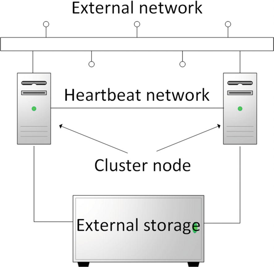
Outline of a Windows two-node cluster. The heartbeat network is for communication between cluster nodes. The external network is for client communication to the workloads on the cluster.
Figure 10-1 shows two machines (known as nodes) in the cluster. A Windows cluster can contain up to 64 nodes (Windows Server 2012 [R2] and Windows Server 2016). Windows Server 2019 extends effective cluster size through the use of cluster sets. A Hyper-V cluster can support up to 8000 VMs, with a maximum of 1024 on any one node.
CLUSTER SET
A cluster set enables you to scale your environment to a higher level. A cluster set is a loosely coupled grouping of failover clusters, for example, four 64-node Hyper-V clusters could be combined into a set to produce a 256-node cluster set. VMs can be migrated between clusters in a cluster set, making your environment more flexible and scalable. The nodes can be split between different physical sites, if required.
You can create fault domains and availability sets within your cluster set. An availability set is used to configure redundancy across fault domains. A fault domain determines which nodes fail together.
More information can be found at https://docs.microsoft.com/en-us/windows-server/storage/storage-spaces/Cluster-Sets .
Both machines are connected to the external network, which is how users access the workloads supported by the cluster. The heartbeat (or internal) network is used by the cluster members to communicate among themselves, in order to confirm that nodes are still available to the network.
The nodes in the cluster have two types of storage. First, each node has one or more disks to support the OS (not shown explicitly in Figure 10-1). Second, there is the cluster storage that is available to all nodes. This is shown as the external storage in Figure 10-1.
External storage is often used to store the cluster quorum.
Cluster Quorum
Cluster startup
Workload placement
Workload failover between nodes
Disk: A specific volume is designated as the witness. The witness disk must be on external storage and can be small (512MB minimum)—1GB is more than sufficient. This is most useful for clusters with non-replicated storage .
File share: An SMB share (5MB minimum free space). The file server should be on a different site from the cluster nodes. The cluster information is held in a witness.log file, rather than a copy of the cluster database. This is most suitable for multisite clusters with storage replication.
Cloud: Azure Blob (Binary Large Object) storage is used to host a read/write file that acts as the witness. Only available in Windows Server 2016 and later versions, this option is best suited to multisite clusters.
ABOVE AND BEYOND
More information on the witness and workings of the cluster quorum can be found at https://technet.microsoft.com/en-us/library/jj612870(v=ws.11).aspx .
The use of a cloud-based witness for Windows Server 2016–based clusters is described here: https://docs.microsoft.com/en-us/windows-server/failover-clustering/deploy-cloud-witness .
If you have an odd number of nodes in the cluster, you can configure the cluster to work on a node-majority basis. In this case, only the cluster nodes have a vote in the quorum, and a witness isn’t required.
Cluster Storage
Cluster Shared Volumes (CSV): These enable multiple nodes to have read/write access to volumes. This is a very common configuration for clusters of Hyper-V hosts and will be used in this chapter.
Fibre Channel attached storage: Usually an SAN
iSCSI: Connects to storage over network. Storage is usually a storage area network (SAN) or network-attached storage (NAS).
Shared virtual disk: This is for Hyper-V guest clusters only.
SMB 3.0 file shares
The option you use will be based on other storage requirements in your organization. Fibre Channel or iSCSI connections to a SAN or NAS are also a common configuration for many enterprises .
ABOVE AND BEYOND
More information on storage options for clusters can be found at https://technet.microsoft.com/en-us/library/hh831579(v=ws.11).aspx .
Windows Server 2016 clustering enhancements are described here: https://technet.microsoft.com/en-us/windows-server-docs/compute/failover-clustering/whats-new-failover-clustering-windows-server .
Now that you understand the basics of clustering, let’s look specifically at clustering Hyper-V.
Clustering Hyper-V Hosts
Many administrators view clustering as very complicated and in the “too hard” category. There are complications, but if you work through the exercises in this chapter and the next few chapters, you’ll learn that it is relatively straightforward.
A Hyper-V cluster can support up to 64 nodes with a maximum 8000 VMs, although it’s probable that your nodes will run out of resources before reaching that number. Each node can support a maximum of 1024 VMs. Exactly how many VMs you can get on a node will depend on the resources (CPU and memory) available to the node and how your VMs are configured.
Note
When designing a cluster, think about the workloads you’ll be supporting. How many nodes do you require to support that number of VMs? Many organizations will design an extra node (called N+1 cluster) into the cluster, to ensure the cluster will function properly, even with one node offline, for example, during patching.
ABOVE AND BEYOND
The article available at https://technet.microsoft.com/library/jj612869 discusses the hardware and storage requirements for clustering in great detail. It should be read before implementing a production cluster.
This is where we tell you that we’re going to cheat in the next few chapters. We’re not going to create the clusters on physical hardware, as most of us don’t have a lab with sufficient machines! We’re going to make use of a new feature in Windows Server 2016 and later versions—nested virtualization—that enables us to create Hyper-V hosts on our Hyper-V host. This isn’t possible in earlier versions of Windows server and Hyper-V. If you can’t use Windows Server 2016 or 2019 and nested virtualization, you’ll need two identical physical machines for cluster nodes. You also have to use the information in Chapter 12, to use a Windows server as an iSCSI target.
Note
Use the evaluation edition of Windows Server 2016 from www.microsoft.com/en-us/evalcenter/evaluate-windows-server-technical-preview . You’ll have to search for the Windows Server 2019 evaluation edition when it becomes available. You could use one of the SAC releases, but they’re Server Core–only, which makes things more difficult. We’re using the Windows Server 2019 preview, so things may change slightly after the full release. Alternatively, you’ll have to use sufficient hardware to create the physical nodes for the cluster.
Virtual Machines for Hyper-V Cluster
Virtual Machine | Purpose | Virtual CPU | RAM | System Disk |
|---|---|---|---|---|
W19HVC01 | Hyper-V cluster node | 4 | 4GB | 125GB |
W19HVC02 | Hyper-V cluster node | 4 | 4GB | 125GB |
Initially, each machine should have a single network adapter. A startup memory of 1024MB and having Dynamic Memory enabled can create the machines, although we’ll have to modify these settings for the cluster nodes later, as nested virtualization doesn’t support Dynamic Memory.
TRY IT YOURSELF
Create the VMs listed in Table 10-1, using the Windows Server Datacenter edition. Configure each machine with a static IP address and join it to your domain.
You’ll be using Storage Spaces (a feature of Windows Server 2016 and later versions) and CSV to create the shared storage for the cluster. This means you must use the Datacenter edition of Windows Server.
Networking for Hyper-V Clusters
Networks Used by the Cluster Nodes
Network | Purpose |
|---|---|
LAN | General network connectivity for users to access VMs |
Heartbeat | Private communication between cluster nodes |
MGMT | Management network. Used by administrators. |
The management network is often not utilized, so we won’t install that one for now. If you’re using iSCSI for storage, you should create a separate network for that traffic (see Chapter 12).
The idea behind using different networks is to segregate network traffic. You can run all cluster traffic—public, private, and management—over a single network. It all depends on your server configuration. If you have two or more 10GB NICs in your servers, you can team them and run all traffic over the team. If have 1GB NICs in your servers, you’ll have to segregate the traffic. If in doubt, segregate the cluster traffic from the workload traffic. The best practice is to separate the traffic, as shown in Table 10-2.
You should create additional VMs to facilitate the network traffic separation, if you are creating your cluster on a Hyper-V host.
Note
If you are creating the Hyper-V cluster with physical machines, you should create virtual networks (VLANs) to perform the traffic segregation. Talk to your network team.
TRY IT YOURSELF
Create the virtual switch on your Hyper-V host, to support the cluster. You should create a switch for at least the heartbeat network. The switch for the management network can be created later, if desired.
With the switch for the heartbeat network created, you can add virtual network adapters to your nodes and configure their IP addresses. We prefer to use a separate addressing scheme for the heartbeat network; it helps to keep things organized. In this case, we’ll use 192.168.40.1 for the heartbeat adapter on W19HVC01 and 192.168.40.2 on W19HVC02.
Repeat for W19HVC02.
W19HVC02 uses the same code, except the IP address is 192.168.40.2.
TRY IT YOURSELF
Create and configure the heartbeat network adapters in your cluster nodes. The heartbeat is, in effect, a ping (but a bit more sophisticated) between the nodes. Test that the heartbeat network can function, by pinging 192.169.40.2 (W19HVC02) from W19HVC01 and 192.169.40.1 (W19HVC01) from W19HVC02.
If the ping doesn’t work, what could be causing the problem?
Make sure that you can ping between the nodes, using the heartbeat addresses, before proceeding.
Once you have the two VMs created, and the network configuration work done, it’s time to configure the storage and create the cluster.
Creating a Hyper-V HA Cluster
- 1.
Create and configure the storage. There will be additional configuration steps post cluster creation.
- 2.
Create and configure the cluster nodes.
- 3.
Create the cluster.
Establishing an ordered process like this breaks down a complex process into manageable steps and reduces errors. It also leads to a more repeatable process, if you create many clusters. In many organizations, the storage and node configuration will be handled by different teams and may well occur simultaneously.
Network Address Ranges for Hyper-V Cluster
Network | Address Range | Subnet Mask |
|---|---|---|
LAN | 10.10.54.0 | 255.255.255.0 |
Heartbeat | 192.168.40.0 | 255.255.255.192 |
The heartbeat network is limited to 62 hosts, because of the subnet mask. If you must use the full 64 nodes available to your cluster, change the subnet mask to 255.255.255.128. All IP address ranges are private addresses, as defined in https://technet.microsoft.com/en-us/library/cc958825.aspx . If your organization has different addressing schemes, substitute accordingly.
The VMs are already created, so the next job is to configure the storage.
Configure Storage
We stated earlier that there were a number of options available to you for configuring storage on your cluster. In this example, we’re going to show you how to use Storage Spaces Direct, which is a feature of Windows Server 2016 and later versions. If you’re using iSCSI, you’ll have to adapt the instructions in Chapter 12.
Storage Spaces Direct (S2D is Microsoft’s acronym) enables you to build highly available storage systems that are virtually shared across your servers. The great advantage is that you use local disks to provide the physical storage, rather than an external storage system. S2D is software-defined storage. The use of Storage Spaces Direct enables you use disks types, such as SATA disks, that would have been unavailable to clusters in the past.
S2D uses disks that are exclusively connected to one node in your cluster. Storage pools are created from those disks. The “virtual disks” known as spaces that are created from the pool have their data spread across the disks in the different nodes of the cluster. This protects your data in the same way as a traditional RAID 1 (mirror) or RAID 5 (parity) storage system.
Note
Using Storage Spaces Direct on the same nodes as your running Hyper-V is an example of converged infrastructure, which is a current industry goal among major vendors.
Disk Configuration for the Cluster
Virtual Machine | Disk | Purpose | Size |
|---|---|---|---|
W19HVC01 | W19HVC01.vhdx | System disk | 125GB |
W19HVC01 | HVC01data01.vhdx | Data disk | 1TB |
W19HVC01 | HVC01data02.vhdx | Data disk | 1TB |
W19HVC02 | W19HVC02.vhdx | System disk | 125GB |
W19HVC02 | HVC02data01.vhdx | Data disk | 1TB |
W19HVC02 | HVC02data02.vhdx | Data disk | 1TB |
Each VM has one disk as the system disk (125GB) and two data disks, each of 1TB in size.
Note
When you create the virtual disks, double-check that you’ve made them dynamic. We don’t have enough storage in our test systems to accommodate 4TB of virtual disks and suspect that you don’t either.
We also decided to put the data disks onto a separate virtual SCSI controller than the system disk. This isn’t totally necessary but shows you another piece of the VM administration puzzle. In a production system, you’d want to separate the disks onto multiple controllers, to avoid the controller becoming a performance bottleneck or a single point of failure.
Note
Adding a new virtual SCSI controller to a VM requires that the VM be shut down. Virtual disks and network adapters can be hot-added but not SCSI controllers.
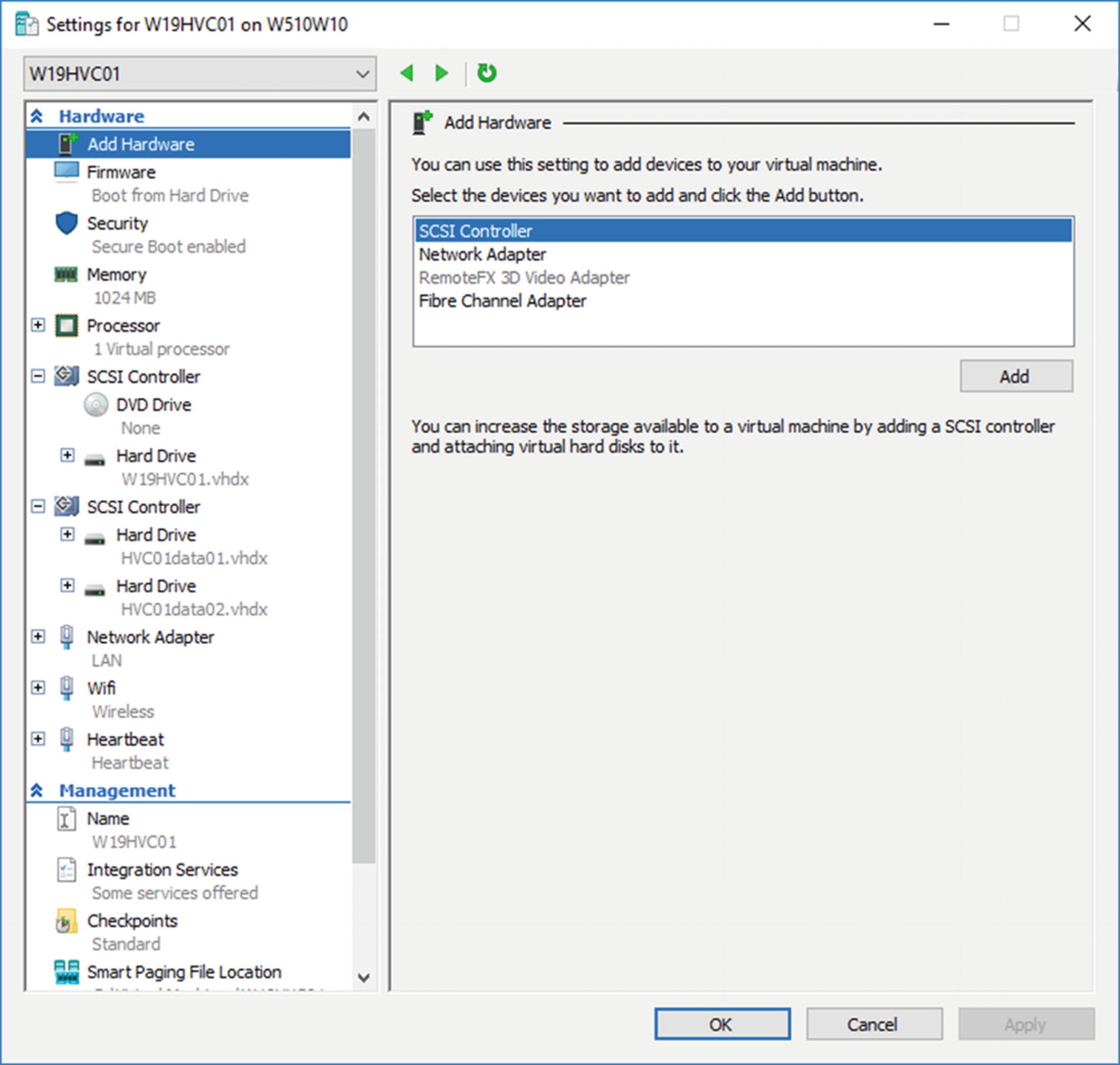
Configuration of the VM after addition of storage and the heartbeat network adapter
You can see the two SCSI controllers in Figure 10-2. The first one (number 0) has the DVD drive and the system disk. The second SCSI controller has the two data disks you just created.
The LAN and heartbeat network adapters are visible toward the bottom of the Hardware list. Ignore the network adapter named Wifi; it’s an artifact of our test lab.
TRY IT YOURSELF
Use the instructions in this section to configure the storage for your cluster.
The storage is ready to use, so it’s time to configure the cluster nodes.
Configure Cluster Nodes
Enabling nested virtualization
Installing the required Windows features
Increases the virtual processors in the VM to 4
Exposes the virtualization extensions—enables nested virtualization
Disables dynamic memory
Increases the memory allocated to the VM to 4GB
Switches on MacAddressSpoofing for the virtual network adapter connected to the LAN VMswitch. This enables VMs hosted on the VM to communicate with other machines on the network that are on other Hyper-V hosts or are physical machines.
TRY IT YOURSELF
Use the instructions in this section to configure the nodes for your cluster.
Your cluster nodes are now configured, so it’s time to create the cluster.
Create Cluster
For each of the nodes, create a credential for the administrator on the node. The credential is used to create a PowerShell remoting session (in this case, using PowerShell Direct, as you’re using the VM name to identify the target). Use the Install-WindowsFeature cmdlet, to add the failover clustering, Hyper-V, and file server features to the machine. You’ll have to restart each node after the installation is complete.
ABOVE AND BEYOND
Creating and configuring two nodes, as you’re doing in this chapter, can be accomplished quite easily by a series of PowerShell commands and GUI actions.
What if you had to create a cluster with 10, 20, 30, or even more nodes? Or what if you had to add nodes to your cluster on a regular basis as your environment grew.
You have two choices. Create a series of scripts that will perform the work for you. Automation will make this task much easier and less error-prone.
The better approach would be to use a configuration management approach, such as Desired State Configuration (DSC), which enables you to define a standard configuration for your nodes and apply it as you create the node. DSC and other DevOps-related topics are discussed in Chapter 19.
- 1.
Open Failover Cluster Manager (Start-Windows Administrative Tools) on W19HVC01 or W19HVC02. You can also perform this from an external administration machine.
- 2.
Click Create Cluster in the Actions pane.
- 3.
Click Next, to skip the Before You Begin page.
- 4.
Enter W19HVC01 on Select Servers page.
- 5.Click Add.
- a.
You’ll see a message about verifying server settings before the server is added to the Selected Servers box, which may take some time, depending on your network.
- b.
Note that the Fully Qualified Domain Name (FQDN) is shown in the Selected Servers box.
- a.
- 6.
Enter W19HVC02 on the Select Servers page.
- 7.
Click Add. You’ll see the same message as in step 5, then the server FQDN will be added to the Selected Servers box.
- 8.
Click Next.
- 9.On the Validation Warning page, click No.
- a.
This bypasses cluster validation. In production, you would want to click Yes, so that the cluster could be validated and would, therefore, be supported by Microsoft.
- b.
If you haven’t seen the validation tests, it’s worth running them to see what is tested. Be warned that they take a few minutes to run.
- c.
The only issue that was reported when we ran the validation on this configuration was that a default gateway wasn’t defined on any of the network adapters. As the lab is a single machine, that is expected.
- a.
- 10.
Click Next.
- 11.
Type a cluster name. Use HVCL01.
- 12.
Click Next.
- 13.
On the Confirmation page, check that the information is correct. If not, use the Previous button, to navigate to the appropriate page, and correct the information.
- 14.
Unselect the Add all eligible storage to the cluster check box. You’ll be configuring storage in the next section.
- 15.
Click Next.
- 16.
The cluster is created.
- 17.
Click View Report, if required. The report shows the steps performed during creation.
- 18.
Close the report.
- 19.
Click Finish.
The cluster is created.
An entry for the cluster is created in AD in the Computers container. It has the failover cluster virtual network name account as the description.
An entry for the cluster is made in DNS, if an IP address was allocated during the creation. If not, it’ll be created later.
Any attached disks are marked as Reserved (if attached to both nodes) or Unallocated (if attached to a single node), in the Disk Management tool on the cluster nodes.
There’s still some configuration work to perform on the cluster.
Cluster Configuration
Configure networks
Configure storage
Configure witness
Let’s start with the network.
Configure Cluster Networking
LAN, on the 10.10.54.0 network. This should be configured for client access and used by the cluster.
Heartbeat, on the 192.168.40.0 network. This should be configured for use only by the cluster.
You also need to allocate an IP address for the cluster.
Configure Networks
- 1.
Open Failover Cluster Manager.
- 2.
Expand HVCL01.
- 3.
Click Networks.
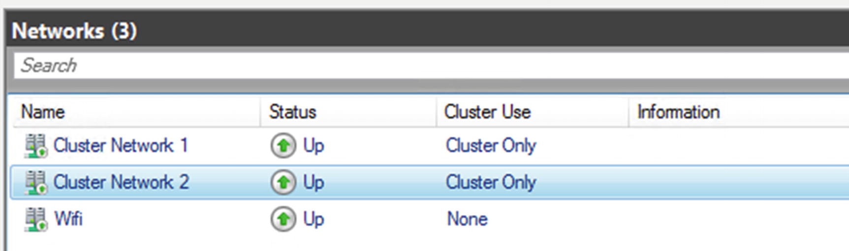
Cluster networks after creation. Ignore the Wifi network.
The networks are named consecutively, and unless you can remember the IP subnet associated with each of the networks and what you intended that network to do, the display isn’t very meaningful.
You can change the names in the display, to show the network’s purpose, and configure how the cluster uses the network.
Change Network Name and Purpose
Allocating descriptive names to the networks will aid you when administering the cluster in the future. Six months from now, you won’t remember which network was meant to do what, so having a descriptive name will save you having to consult the documentation (you did document your cluster, didn’t you?).
- 1.
Open Failover Cluster Manager.
- 2.
Expand HVCL01.
- 3.
Click Networks.
- 4.
Right-click the required network. You may have to click through the networks to determine which subnet they are on.
- 5.
Click Properties.
- 6.
Based on the subnet, change the name, as shown in Figure 10-4.
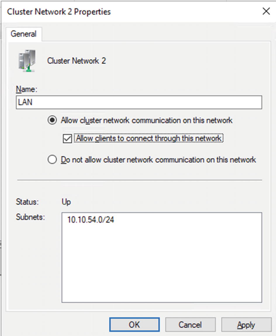
Setting the network name and purpose
- 7.
Depending on the network, configure if cluster network traffic is allowed on the network, as shown in Table 10-5.
Traffic Allowed on the Cluster Networks
Network | Traffic Setting |
|---|---|
Heartbeat Network | Allow cluster network communication on this network. |
LAN Network | Allow cluster network communication on this network. Allow clients to connect through this network. |
TRY IT YOURSELF
Change the network names to match those in Table 10-5 and check the subnets against your design documentation.
Check whether the traffic settings match those in Table 10-5.
Set Cluster IP Address
Your cluster nodes were configured with an IP address, so that they can be on the network. Your cluster itself also needs an IP address.
- 1.
Open Failover Cluster Manager.
- 2.
Expand HVCL01.
- 3.
Under Cluster Core Resources (at the bottom in the center), right-click Name: HVCL01.
- 4.
Select Properties.
- 5.
Remove any network and IP address information by selecting it and clicking Remove.
- 6.
Click Add.
- 7.
Select the network and set an IP address, as shown in Figure 10-5.
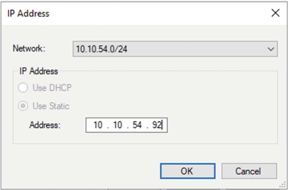
Setting the cluster IP address
- 8.
Click OK.
- 9.
You should see something like Figure 10-6.
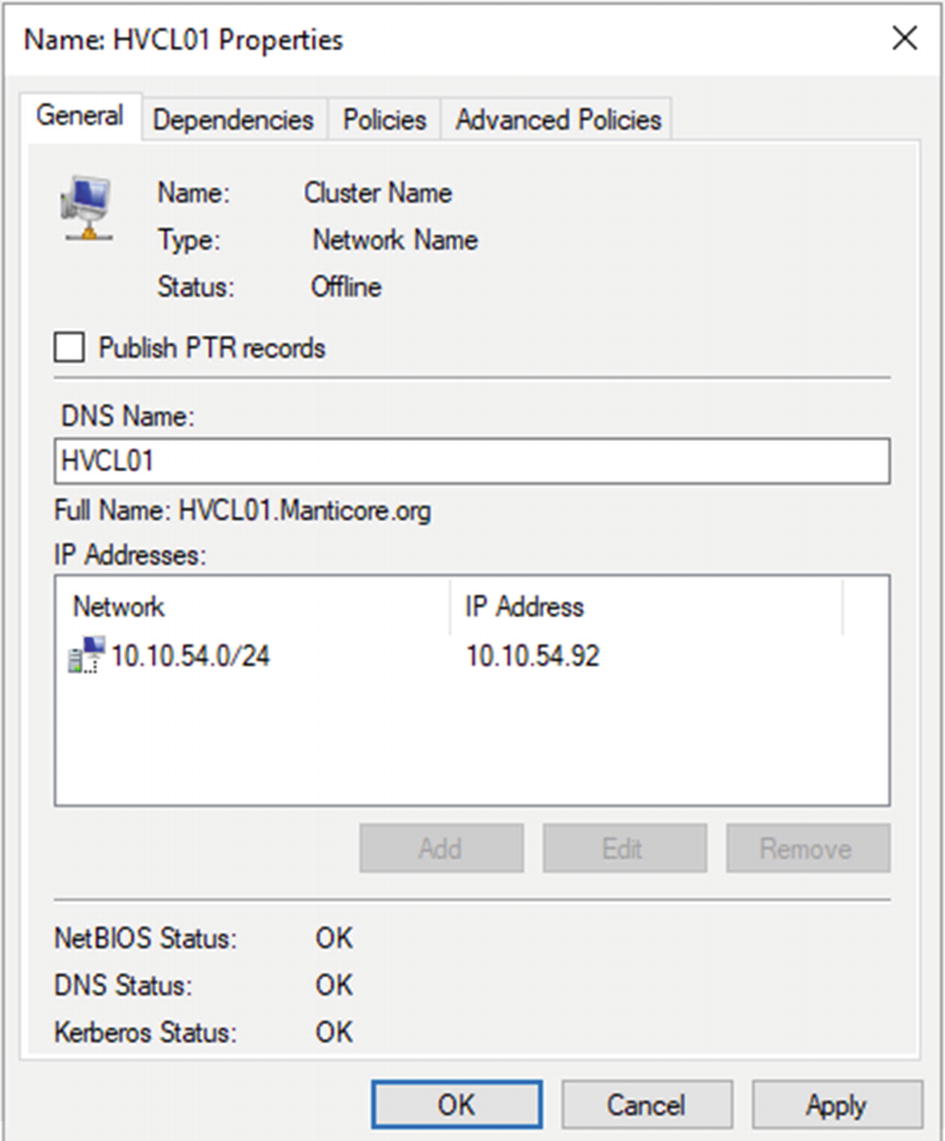
Cluster IP address setting
- 10.
Click OK.
- 11.
Under Cluster Core Resources (at the bottom in the center), right-click Name: HVCL01.
- 12.
Click Bring Online.
- 13.
The Cluster Core Resource display should change to show that the IP address and the cluster are online.
- 14.
Check that the new IP address for the cluster is present in DNS.
TRY IT YOURSELF
Set the cluster IP address for your cluster. Check that a record exists in DNS and AD.
With the cluster networks configured, it’s time to finish configuring the storage.
Configure Storage Spaces Direct
You’ll be asked to confirm the action. The creation of the storage pool takes a little while. Once the creation has finished, you’ll see that a 10GB Cluster Virtual Disk has been created (look in Failover Cluster Manager ➤ HVCL01 ➤ Disks) for the cluster performance history, and a 4TB storage pool has been created (Failover Cluster Manager ➤ HVCL01 ➤ Pools).
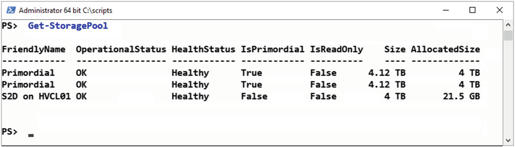
Newly created storage pool
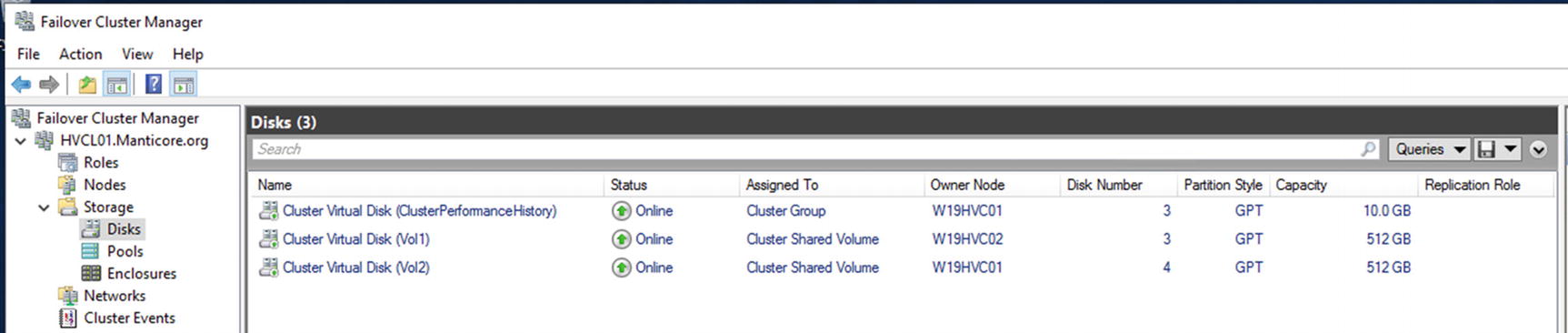
The cluster has three disks: Vol1, Vol2, and ClusterPerformanceHistory
Vol1 and Vol2 are automatically configured as CSV. They are accessible through the filesystem on each node at C:ClusterStorage. Within C:ClusterStorage is a mount point for each volume you created.
TRY IT YOURSELF
Configure the storage on your cluster, following the instructions in this section. Check that the newly created volumes are visible from both nodes and that mount points exist for the CSV on each node.
The last job you have to do is to configure the witness.
Configure Witness
As we stated earlier, the cluster witness or quorum can be disk-, file share–, or cloud-based. For the current cluster, you’ll configure a file share witness.
- 1.
Open Failover Cluster Manager and select HVCL01.
- 2.
Under Actions (right-hand side) select More Actions.
- 3.
Select Configure Cluster Quorum Settings…
- 4.
Click Next, to bypass the Before You Begin page.
- 5.
Select Advanced quorum configuration.
- 6.
Click Next.
- 7.
Ensure that All Nodes is selected and click Next.
- 8.
Select Configure a file share witness.
- 9.
Click Next.
- 10.
Enter the file and share path. If you click Browse, you can select the server and share, or even create, a new share. Ensure that the cluster HVCL01 has full control of the folder used for the share.
- 11.
Click Next.
- 12.
Check information on Confirmation screen and click Next.
- 13.
The witness will be created.
- 14.
Click Finish, to exit wizard.
You’ve created the witness for your cluster and have finished the initial configuration work. This has been a long chapter, so we’ll leave you to complete the lab. In the next chapter, we’ll show you how to manage the cluster and create VMs.
Lab Work
- 1.
Complete the Try It Yourself sections in this chapter.
- 2.
Complete all steps in the section “Creating a Hyper-V HA Cluster” to create a cluster.
- 3.
Complete the actions in the section “Cluster Configuration,” to configure the cluster.