So far, we’ve focused on the use and configuration of virtual machines (VMs). We’ve built a number of VMs, but they’re not yet able to talk to the physical network. In this chapter, we’ll configure the networking on the host, so that VMs can connect to the physical network .
In This Chapter and Beyond
We’re going to focus on the Hyper-V host itself, for the next couple of chapters. You’ll be learning about the basics of networking in Hyper-V in this chapter, after which, we’ll go on to discuss some more advanced storage concepts in Chapter 9, because with some storage solutions, TCP/IP networking is a requirement. These topics are necessary, as they will round out your ability to manage and maintain a stand-alone host and prepare you for the later chapters. Let’s get started!
Introduction to the Hyper-V Extensible Switch
You’re getting a good grasp of virtualization concepts. We’re taking all of these historically physical objects, such as CPU, memory, and storage, and we’re abstracting them as software-defined entities. You’ve seen how this is done by allocating CPU time to a VM or increasing the amount of memory a VM has access to. This type of abstraction also applies to networking.
In earlier chapters, we’ve briefly mentioned virtual network interface cards (NICs). Another common name is network adapter. These virtual NICs attach to your VM’s function in much the same way as a physical NIC. They use the same protocols and the same transport mechanisms. With that in mind, shouldn’t they be able to talk to a physical switch as well? The answer to that question is yes, but we have to allow the traffic to get to the physical network first. This is where the Hyper-V Extensible Switch comes into play.
We’re abstracting the networking layer (just like compute and storage), including the switching component. Each Hyper-V host can create one or more virtualized switching entities called a virtual switch, or vSwitch for short. You can imagine these vSwitches as similar to a VM, in that they are intangible objects that exist within the host. These entities are associated with the physical network cards in the host system.
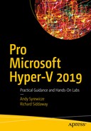
Basic logical layout of Hyper-V networking, with connectivity to the physical network
The virtual NICs attached to each VM are “plugged in” to a virtual switch residing on the Hyper-V host. That virtual switch in turn uses the physical NIC in the host as a type of uplink, to gain access to the rest of the switch infrastructure. In practice, it’s no different than two physical switches talking to each other.
This connectivity is the most basic function of the Hyper-V Extensible Switch, and it is what we’ll be focusing on throughout this chapter, because our virtualized workloads are useless if we can’t talk to them over the network.
ABOVE AND BEYOND
The Hyper-V Extensible Switch has a number of integration features baked into it, so that third-part vendors can program additional functionality for it. For instance, Cisco has created the Nexus 1000x switch for Microsoft Hyper-V, which makes the Hyper-V Extensible Switch function and feel like a Cisco Nexus device. This allows your networking and support teams to support the virtualized infrastructure in much the same way that they would support the physical infrastructure. Details are available at www.cisco.com/c/en/us/products/switches/nexus-1000v-switch-microsoft-hyper-v/index.html . Keep this in mind as you continue to build on your Hyper-V networking knowledge throughout this book.
Virtual Switch Types in Hyper-V and Their Uses
Microsoft has provided a number of virtual switch types for use in Hyper-V environments. We have quite a bit of flexibility when it comes to controlling how vSwitches behave in Hyper-V. You have to define the switch type at the time you create it. We’ll cover each type and what its primary use is.
External Virtual Switch
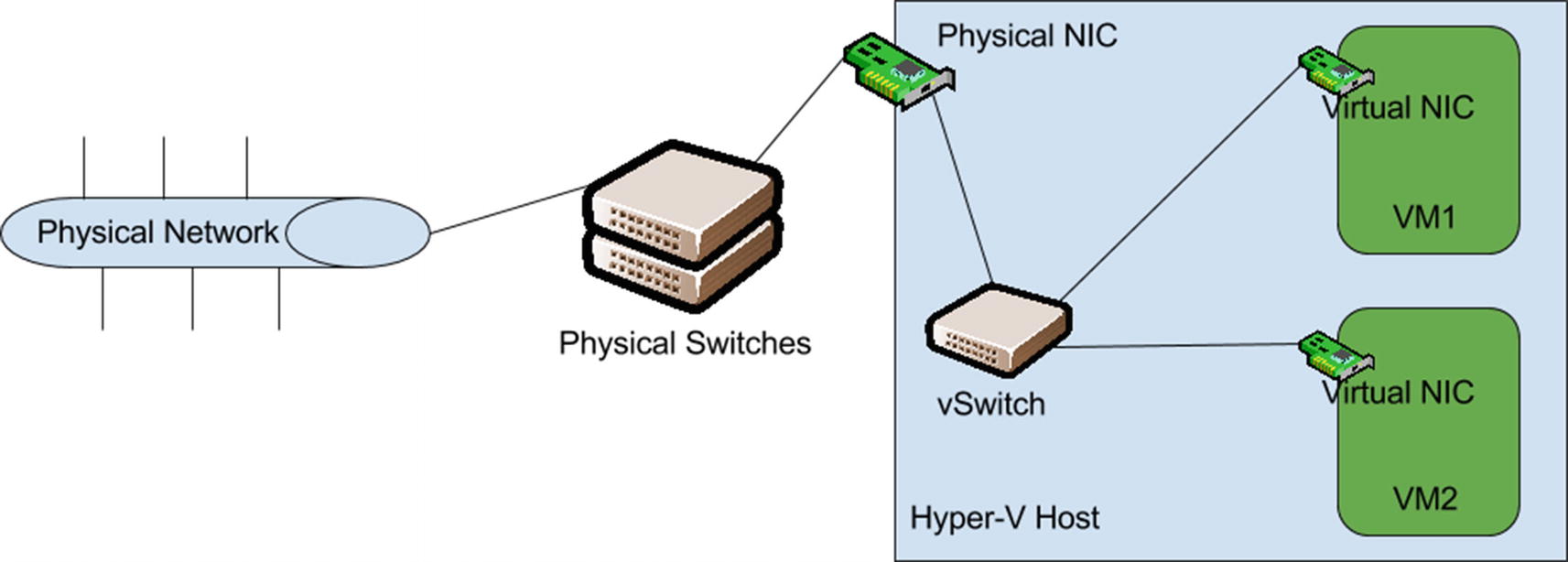
This is the type of vSwitch you’ll be creating and using 90% of the time, usually for connecting VMs to the physical network. This virtual switch type provides communication between VMs on the host and external network connectivity. Figure 8-1 is the perfect example of an external vSwitch configuration. This is the default switch type when creating a new switch, as you’ll see shortly.
Internal Virtual Switch
An internal virtual switch does not provide access to the physical network. This type of switch will allow VMs attached to it to talk to each other and to the host system. If you’re running a lab in which you want to simulate entire environments and ensure that the test environment is isolated from the production network, you’d use an internal virtual switch to guarantee that isolation. Or, let’s say you have a VM that requires additional network isolation because you’re working in a high-security environment.
Internal vSwitch use case example for inline security appliances
As you can see in Figure 8-2, network traffic from VM2 has to traverse VM1 to get to the physical network. VM2 cannot talk to the network without VM1, so extra configuration needs to be performed, to ensure those two VMs stay together at all times on the same host. This idea will be covered later on when we discuss virtual machine mobility.
Private Virtual Switch
This virtual switch type is exactly the same as the internal vSwitch type, except a private virtual switch will not allow the host to talk with the VMs attached to the vSwitch. You’ll still be able to connect with the console to those VMs and manage them normally, but from a networking standpoint, the host will not be able to access those workloads. You would use this vSwitch type when you don’t want the host itself to be able to see the IP traffic of the VMs attached to this vSwitch. You’ll see this type of switch used for internal cluster traffic when we discuss clustering.
Creating a Hyper-V Virtual Switch
- 1.
In Hyper-V Manager, select your Hyper-V host.
- 2.
In the right-hand pane, click Virtual Switch Manager. You’ll be greeted by a screen similar to that shown in Figure 8-3.

Virtual Switch Manager UI, with which you can choose a vSwitch type
- 3.
Make sure virtual switch type External is highlighted, then click Create Virtual Switch.
- 4.
On the next screen, as shown in Figure 8-4, give the new virtual switch a name and attach any notes you might want to track, such as subnet information.

Virtual Switch Properties UI for configuring vSwitch settings
- 5.
Check that Connection type is External and then select in the host the physical network adaptor that will be used to connect this vSwitch to the physical network, using the drop-down.
- 6.
Leave the Allow management operating system to share this network adapter check box checked.
- 7.
Leave Enable single-root I/O virtualization (SR-IOV), and Enable virtual LAN identification for management operating system unchecked, then click Apply.
- 8.
When the Apply Networking Changes dialog comes up warning you that this may interrupt network connectivity, click Yes to continue.
- 9.
Verify that the new virtual switch appears in the Virtual Switches list in the left-hand pane of the Virtual Switch Manager UI.
- 10.
Click OK to exit the Virtual Switch Manager UI and return to the main Hyper-V Manager screen.
TRY IT YOURSELF
Create an external vSwitch on your Hyper-V host.
You should now have a functional external vSwitch on your Hyper-V host! If your organization has a separate VLAN for traffic management, you’ll want to enable the option and input the VLAN ID, as requested. If you’re not sure about this, you either don’t require this, or you need to discuss it with your networking team.
ABOVE AND BEYOND
Another check box that you likely noticed here is that for single-root I/O virtualization. SR-IOV is a technology that allows hypervisors to gain more direct access to the networking hardware in the host, to provide better performance in high-throughput situations. This is a bit of an advanced topic, and if you’re interested in learning more about it, see the MSDN overview regarding this feature here: https://msdn.microsoft.com/en-us/library/windows/hardware/hh440148(v=vs.85).aspx .
Attaching Virtual Machines to a vSwitch
Now that you have a working vSwitch, you need to assign a virtual NIC from a VM to the new external vSwitch, so that the VM can communicate with the physical network and your users can access the VM’s workload.
- 1.
In Hyper-V Manager, select the Hyper-V host with the VMs you created in Chapter 3.
- 2.
In the center pane, identify a target VM for this operation.
- 3.
Select the target VM, then click Settings in the right-hand pane.
- 4.
In the settings UI for the target VM, click Network Adapter, in the left-hand window, as shown in Figure 8-5.

Network Adapter Settings UI for a VM, which contains settings for the vNIC
- 5.
Using the Virtual switch drop-down, select the vSwitch that we created earlier.
- 6.
Leave the two check boxes on this screen unchecked, then click Apply.
- 7.
Close the Virtual Machine Settings UI.
- 8.
Using Hyper-V Manager, open the console for the target VM and log in to the guest OS.
- 9.
Open a command prompt or PowerShell window and verify that an IP was obtained by DHCP. If you don’t have DHCP on this LAN segment, manually set the IP address.
- 10.
Attempt to ping the gateway of the network. You should now have network connectivity inside of the guest OS of this VM.
TRY IT YOURSELF
Attach a VM to your external vSwitch.
The virtual switch assignment is really the only option that’s needed to get the VM talking with the network, assuming you don’t require the VM on a specific VLAN. If you do, you’ll need to enable the VLAN ID check box and assign the appropriate VLAN ID. The other option you’ll see on the VM NIC settings UI is “Enable bandwidth management.” This option is especially useful, if you want to cap the amount of network bandwidth a specific VM is allowed to have, where you have one VM that likes to attempt to monopolize all of your network throughput.
Managing vSwitches with PowerShell
Attaching a VM to a vSwitch in PowerShell is another step in extending your automation capabilities when creating new VMs.
Management Network Considerations
There is an option in the virtual switch settings that allows the management OS to share the network adapter that was being assigned to a virtual switch. Remember that even though you’re providing networking capabilities to your VM, the host system itself needs network connectivity for such things as management, patching, and monitoring. When a new virtual switch is configured, by default, Hyper-V will allow the host’s OS also to use that same physical NIC for these management tasks. This is where administrators start asking whether that is a good idea, and the answer to that question is, It depends.
It depends on the type of physical network adapters you have and how many of them you have. If you’re lucky enough to have a host with dual 10GB or 40GB network adapters in it, then you should be completely fine running management traffic over those NICs. However, if you have a number of 1GB NICs on the host, you may want to consider separating the management traffic.
For a single OS, 1GB of throughput is still adequate, but remember, your host may be running 5, 10, 20, or more VMs, and it’s quite likely that a single 1GB NIC could quickly become saturated. If that happens, you’re going to have to remote into the host, so you need sufficient network bandwidth. In that case, you may want to set aside one or more physical NICs specifically for management purposes, while the other NICs in the host are used for VMs and other tasks.
Additionally, if you want added resiliency, you can use the NIC teaming features in Windows Server, to make redundant teams of physical NICs for your management traffic and also for your VM traffic.
NIC Teaming
At some point, all physical hardware will fail, including NICs and switches. Also, physical cables frequently get bumped or pulled out, which could cause an outage. NIC teaming protects against these events, and it’s doubly important when Hyper-V enters into the discussion.
When Hyper-V hosts critical production workloads, you want to ensure that the uptime is near 100%. To facilitate this, it’s recommended to use NIC teaming in your Hyper-V hosts wherever possible. Microsoft incorporates NIC teaming in Windows Server 2012 and later versions. With this technology, we can set up fault-tolerant teams of NICs for management, storage, and VM network traffic. If one NIC in a team fails, the other NIC(s) in the team will continue to send traffic through, until you can schedule downtime for the affected system to replace the NIC.
Let’s set up a new NIC team on our host, and then we’ll modify the virtual switch to use the new NIC team for connectivity to the physical network.
- 1.
Open Server Manager on your Hyper-V host.
- 2.
Click All Servers in the left-hand pane and locate your Hyper-V host in the list. If your host isn’t visible, add it by clicking Manage on the top control bar, and click Add Servers.
- 3.
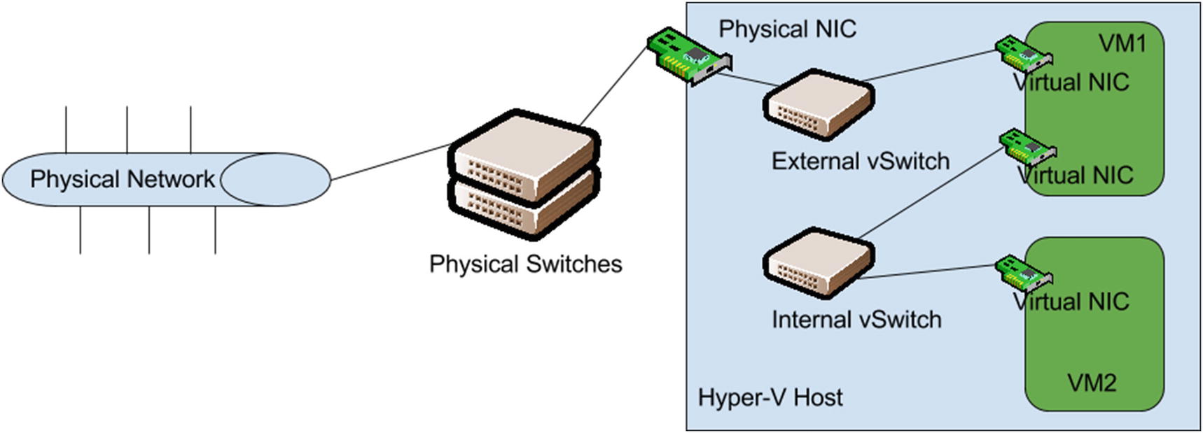
Right-click the target Hyper-V host and click Configure NIC Teaming. This will open the NIC Teaming UI , as shown in Figure 8-6.
NIC Teaming UI in Server Manager
- 4.
In the lower-right section of the screen, under Adapters and Interfaces, select two or more NICs, click the Tasks drop-down, and then click Add to New Team.
- 5.
Name the New NIC Team, verify that the correct adapters are selected, and then click OK.
- 6.
Close the NIC Team UI and then Server Manager.
- 7.
Open Hyper-V Manager on your Hyper-V host and open the Virtual Switch Management UI once again, as shown earlier in this chapter.
- 8.
Select the virtual switch that was created earlier in this chapter, and using the Adapters drop-down, select Microsoft Network Adapter Multiplexor Driver. (This is the name used by the NIC teaming driver.)
Note
It can sometimes be difficult to determine which NIC team to select, when you’re using multiple NIC teams. In this situation, you can modify the interface description for the team, by using the following syntax: Set-NetAdapter -Name 'AdapterName' -InterfaceDescription 'Description'.
- 9.
Click Apply and wait for the settings to take effect.
- 10.
Verify that you can remotely ping the host system by DNS name or IP address .
- 11.
Log in to the guest VM that was connected to the network earlier in this chapter and verify that it can still ping the gateway.
TRY IT YOURSELF
Create an NIC team on your Hyper-V host.
Now that you’ve configured a NIC team, if one of those two NICs fails, any virtual machines attached to that vSwitch will still have access to the network, and you’ll still be able to remotely manage the host. This adds a very important layer of protection to your virtualized workloads. When specifying hardware for Hyper-V hosts, it’s always helpful to have sufficient NICs to enable teaming.
NetSwitchTeam for use with Hyper-V extensible switches: https://docs.microsoft.com/en-us/windows-hardware/drivers/network/overview-of-the-hyper-v-extensible-switch
NetLBfo for NIC teaming
REGARDING WINDOWS SERVER 2016
Windows Server 2016 introduced an alternative NIC teaming mode called Switch Embedded Teaming (SET) that boasts a number of improvements and enhancements when used with the new Software Defined Networking (SDN) stack. If you’d like to read up on this new feature, feel free to review the informational page located at https://technet.microsoft.com/en-us/library/mt403349.aspx#bkmk_over .
It’s time for a lab to consolidate your learning.
Lab Work
- 1.
Use Hyper-V Manager to create an additional vSwitch of the internal type.
- 2.
Add a second NIC to the VM that is already connected to the physical network and attach this new NIC to the internal vSwitch you just created.
- 3.
Attach the NIC in the second VM that you didn’t use earlier to the internal vSwitch you just created.
- 4.
Configure the virtual NICs on each VM attached to the internal vSwitch for the 10.0.50.x network with a subnet mask of 255.255.255.0 and no defined gateway or DNS.
- 5.
Once configured, verify that the two VMs can ping each other on the 10.0.50.x network.