
Chapter 17
Using Layer Diagrams to Model and Enforce Application Architecture
What's in this chapter?
- Understanding a layer diagram
- Creating a layer diagram
- Defining dependencies on a layer diagram
In the other chapters in this section of the book, you learned about some of the different modeling diagrams available in Visual Studio Ultimate 2013. This chapter examines the final diagram—the layer diagram.
Layer diagrams are used to describe the structure of an application at a high level. You can also use these diagrams to verify that the developed code conforms to the high-level design laid out in the layer diagram. One nice feature about layer diagrams is their capability to validate application design architecture against the code base, ensuring that the code and architecture continue to match during the development process.
In a way similar to a traditional architecture diagram, a layer diagram shows the major components of the architecture design. Dependencies between the components are also laid out on the diagram. A diagram consists of one or more nodes, referred to as layers. A layer can represent any sort of logical group—for example, a namespace or a class file. Dependencies on a layer diagram can be defined explicitly based on your proposed architecture, or you can have the tool discover them from the existing relationships in the code. You can also incorporate layer diagrams into the automated build process, which enables you to verify that code changes adhere to the architectural design.
This chapter examines layer diagrams in detail. You first learn how a layer diagram is created. Next, you find out how to add layers to a diagram, both by using the toolbox and by building layers from an existing code base. You see how you can use the Layer Explorer to provide a detailed look at which artifacts are contained within a layer. The chapter wraps up by looking at layer validation, and how to include layer validation in the build process.
Creating a Layer Diagram
To use a layer diagram, you must add a new one to the solution with which you are currently working. Creating a new blank layer diagram requires the use of either an existing modeling project, or the creation of a new modeling project in the current solution. Because layer diagrams are simply another type of diagram in Visual Studio, they must have a modeling project to be stored in.
To create a new blank layer diagram in the solution, select Architecture from the Visual Studio main menu, and then select New Diagram. This opens the Add New Diagram window, as shown in Figure 17.1.
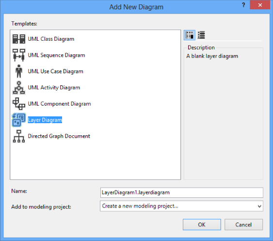
In the Add New Diagram window, select the Layer Diagram. In the Name field, enter the name of your layer diagram. All layer diagrams end in .layerdiagram
If the solution contains an existing modeling project, you can select it in the Add to Modeling Project drop-down box. If the current solution does not contain a modeling project, then select Create a New Modeling Project in the drop-down box, and the Add New Diagram window prompts you to create a new modeling project.
After you have selected the layer diagram model type, given a name to the model, and selected the appropriate option from the Modeling Project drop-down box, click the OK button. If a new modeling project is being created, the Create New Modeling Project window opens.
Modeling Project is the only option available for creating a new modeling project, although you can control the .NET Framework support for the modeling project by selecting the appropriate version for the framework at the top of the window. Enter a name for the modeling project and the location to store the project and then click OK. The modeling project is created; a new blank layer diagram is created inside the modeling project; and the new blank layer diagram opens in a tab in Visual Studio.
Defining Layers on a Layer Diagram
The next step is to define the different layers on the layer diagram. Each layer on a layer diagram appears as a rectangle. Different layers can be nested inside each other, which is called grouping. The different layers in a layer diagram are used to define logical groups of artifacts, including methods, classes, and namespaces.
You can define layers on the layer diagram by dragging objects from the layer diagram toolbox, dragging objects from Solution Explorer, or dragging objects from the Architecture Explorer. The easiest way is to use the layer diagram toolbox. Use the objects in the layer diagram toolbox to define a layer diagram with three Sections.
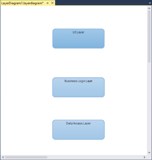
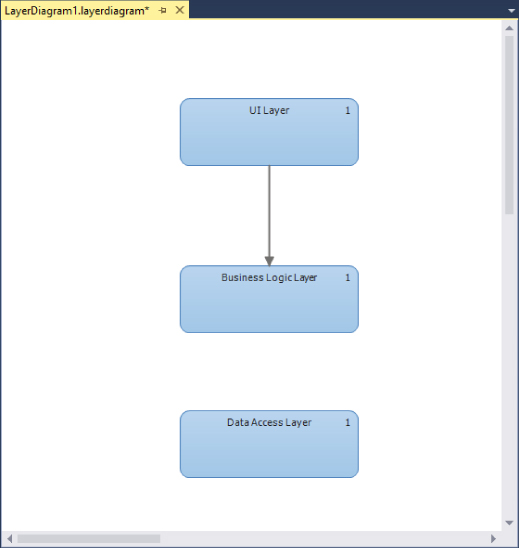
- Drag a layer object from the toolbox onto the blank diagram. A rectangle appears on the diagram with the default name Layer Double-click the layer and change the name to UI Layer.
- Drag another layer object from the toolbox and place it directly below the UI Layer object. Double-click this object and rename it Business Logic Layer.
- Drag a third layer object onto the diagram below the other two and rename it Data Access Layer. Figure 17.2 shows what the layer diagram should look like at this point.
For each layer, you can specify certain properties by selecting the layer object, and referring to the Properties window in Visual Studio:
- Forbidden Namespaces—Use this property to specify that artifacts associated with a layer must not belong to the specified namespaces. Separate each namespace with a semicolon (;).
- Forbidden Namespace Dependencies—Use this property to specify that artifacts associated with a layer cannot depend on the specified namespaces. Separate each namespace with a semicolon (;).
- Required Namespaces—Use this property to specify that artifacts associated with a layer must belong to one of the specified namespaces. Separate each namespace with a semicolon (;).
At this point, you have created three “unlinked” layers. The layers are referred to as unlinked because currently no code files are associated with them. This is useful to help represent different parts of an application that have not yet been developed. You continue to build off this layer diagram later in this chapter. But, for now, let's continue to look at the different ways layers can be added to a layer diagram.
Creating a Layer for a Single Artifact
As mentioned previously, a layer represents a logical grouping of artifacts. There may be times when a single artifact (such as a project, or even a single code file) must be represented as its own layer. This is easy to do with a layer diagram. In fact, you can use any of the following sources to add layers to a layer diagram:
- Solution Explorer—From within Solution Explorer, you can drag and drop any file or project contained in the Solution Explorer onto the layer diagram surface. A new layer is created with the name of that file or project, and it contains a link to the file or project.
- Architecture Explorer—Using the Architecture Explorer, you can drill down to the information you are interested in (such as namespaces) and drag and drop those namespaces onto the surface. Those namespaces appear as layers on the diagram, again with the layer linked to the information that was dropped onto the diagram.
- Dependency Graphs—You also have the capability to drop dependency graph information directly onto a layer diagram to create layers.
Adding Multiple Objects to a Layer Diagram
When you drag and drop multiple items to a layer diagram at the same time, the default action is to create a single layer on the diagram, with all the objects contained within that layer. To create a separate layer for each artifact dropped as a group, simply hold down the Shift key while dropping the artifacts onto the layer diagram. A layer for each artifact appears on the diagram, and each layer is linked to its appropriate artifact.
To add an artifact to an existing layer, simply drop the artifact onto an existing layer on the layer diagram. A link is established between the layer and the artifact.
The Layer Explorer
To understand how links are added to a layer diagram and how to view the linked information between a particular layer on a layer diagram and its linked artifacts, let's continue to build off the layer diagram from Figure 17.2.
From Solution Explorer, click FirstClass.cs1SecondClass.cs1ThirdClass.cs
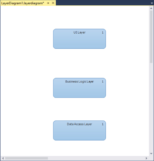
In Figure 17.3, you see three layers, with each layer containing one artifact. But how do you go about viewing which artifacts are contained within which layers? That is where the Layer Explorer comes in.
You use the Layer Explorer to view artifacts that are linked to a particular layer and to move artifacts between layers. To open the Layer Explorer, right-click a layer in the layer diagram and select View Links. By default, the Layer Explorer opens on the right side of Visual Studio, usually as a tab in the same window as the Solution Explorer, as shown in Figure 17.4.
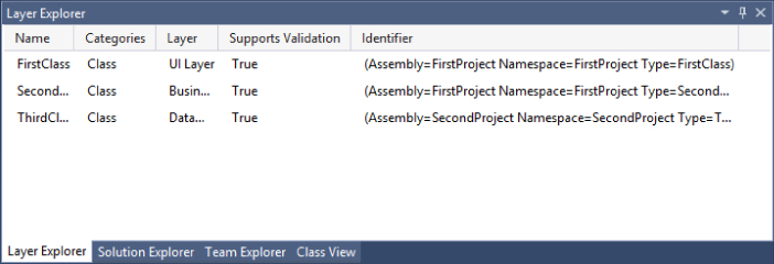
The Layer Explorer displays all the artifacts that are linked to a particular layer. As shown in Figure 17.4, the Layer Explorer contains a series of columns that display different properties about the linked artifacts:
- The Name column displays the name of the linked artifact.
- The Categories column displays information about the type of artifact. This could be class, namespace, or project file, just to name a few.
- The Layer column displays the layer that the artifact belongs to.
- The Supports Validation column indicates whether the linked artifact participates in the layer-validation process. If this column is set to
FalseTrue - The Identifier column is used to provide a reference to the linked column.
To display all the artifacts on a layer diagram, click anywhere on the white space area of the layer diagram. This deselects any layers that have been selected, which, in turn, displays all the artifacts linked to different layers in the Layer Explorer.
To delete an artifact from the layer diagram, select the artifact in the Layer Explorer, right-click the artifact, and select Delete. This deletes the artifact from both the Layer Explorer and the layer diagram.
To move an artifact from one layer to another, you have a couple of options. In the Layer Explorer, you can right-click the artifact in question and select Cut. Then, in the layer diagram, right-click the appropriate layer and select Paste. Also, you can simply drag the artifact from the Layer Explorer onto a layer on the layer diagram. The artifact is removed from its initial layer and added to the new layer.
An artifact can be a member of multiple layers. One way to add an artifact to multiple layers is to drag the object onto the multiple layers from Solution Explorer. A second option is to right-click the artifact in the Layer Explorer, select Copy, and then right-click the layer in the layer diagram and select Paste. In either event, a second instance of the artifact appears in the Layer Explorer, but it's linked to a different layer.
Defining Dependencies
After you have defined the layers in the layer diagram, the next step is to identify the dependencies between the different layers. A dependency between two layers exists whenever an artifact that exists in one layer references or uses an artifact that exists in another layer. For example, a dependency exists between the Business Logic Layer and the Data Access Layer when a class in the Business Logic Layer calls or makes reference to a class in the Data Access Layer.
Depending on how the layer diagram was built, you may want to have the dependencies discovered for you automatically, or you may want to define them by hand. More than likely, you will use a combination of the two options.
If the layer diagram was created by dragging existing code artifacts onto the diagram (such as files from a project in Solution Explorer or Architecture Explorer), then the dependencies between the different layers in which those objects exist can be found automatically. If you right-click the layer diagram surface and select Generate Dependencies, Visual Studio analyzes the artifacts that exist in each layer, identifies all the dependencies between the different artifacts, and then represents those dependencies on the layer diagram as a series of arrows connecting one layer to another.
A dependency can be a uni-directional dependency, meaning that Layer 1 is dependent on objects in Layer 2, but Layer 2 is not dependent on any objects in Layer 1. Dependencies can also be bi-directional, meaning that, just as there are objects in Layer 1 that depend on Layer 2, there are objects in Layer 2 that depend on Layer 1.
Dependencies on a layer diagram can also be defined by hand. This is helpful especially when you are creating the layer diagram as part of the design phase. In that phase, you don't know the specific code artifacts that you will be creating. But you do know the different high-level areas of your application, and you want to define how they will interact or depend on each other.
Let's use the layer diagram from Figure 17.3 and add some dependencies between the different layers. In the layer diagram, you have three different layers: the UI Layer, the Business Logic Layer, and the Data Access Layer.
The UI Layer is dependent on artifacts in the Business Logic Layer. Without the Business Logic Layer, there is no information for the UI Layer to display. This dependency is represented by using a Dependency object from the layer diagram area of the Visual Studio toolbox. Click the Dependency object in the layer diagram area of the Visual Studio toolbox. Then, on the layer diagram, click the UI Layer followed by the Business Logic Layer. A dependency arrow connects the two layers, stretching from the UI Layer to the Business Logic Layer, as shown in Figure 17.5.
A Dependency object has properties, just like any other object in Visual Studio. The property window in Visual Studio displays the properties available. You can define a name and include a description of the dependency. You can also control the direction of the dependency arrow here. If you need to reverse the direction, select Backward in the Direction property. You can also turn the dependency into a bi-directional dependency by selecting Bi-Directional in the Direction property.
You also have a dependency between the Business Logic Layer and the Data Access Layer. The Business Logic Layer cannot perform its functions, or provide information to the UI Layer, without information from the Data Access Layer. Using the same method described previously, you can create a dependency between the two layers (you select the Dependency object and connect the Business Logic Layer and the Data Access Layer).
Dependencies cannot be generated for certain types of artifacts in a layer diagram. For example, if you add a text file to a layer in a layer diagram, there are no dependencies generated either to or from that particular layer around that text file. To determine if an artifact is going to generate dependencies, select the layer that contains the artifact and open the Layer Explorer by right-clicking the layer and selecting View Links. In the Layer Explorer, if the value in the Supports Validation column is set to False
Validating the Layer Diagram
At this point, you may be saying to yourself, “Okay, layer diagrams are great and all, but what is the actual benefit to me? Why do I want to go to all this effort of creating different layers and linking my code artifacts to these different layers?” The answers to these questions lie in the capability to validate the architecture.
Validation enables you to confirm that all the dependencies defined between all the different layers are being respected. This provides the capability to enforce rules and dependencies between different layers. For example, you may have segregated your code base where different namespaces are not supposed to interact. You can define that segregation using a layer diagram and dependencies, and then add your code artifacts to their appropriate layers. If a developer miscodes something (such as accessing a namespace she is not supposed to access), it may not be readily apparent by just looking at the code. However, by using the validation features of a layer diagram, an error is immediately thrown, pinpointing the problem area, so that you can quickly and easily resolve it.
To validate a layer diagram, right-click anywhere on the layer diagram and select Validate Architecture from the context menu. Visual Studio analyzes the layer diagram, as well as all the artifacts associated with the layer diagram. It follows all the dependencies to ensure that there are no violations.
If no problems are found, a message is displayed in the output window that the architecture validation has succeeded. If problems are discovered in the layer diagram validation, they are displayed in the Error List window in Visual Studio.
Using the layer diagram from Figure 17.5, let's look at an example of validating the diagram. To validate the layer diagram as it exists in Figure 17.5, right-click the layer diagram and select Validate Architecture. Visual Studio goes through the validation process, including compiling the code, and then verifies any dependencies that exist on the diagram. Figure 17.6 shows the results from the Output window in Visual Studio.
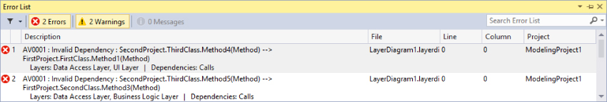
There are two validation errors in the layer diagram. The errors indicate that a dependency on the layer diagram has not been satisfied. In the layer diagram shown in Figure 17.5, the UI Layer contains the class named FirstClassSecondClassThirdClassThirdClassFirstClassSecondClass
Because the dependencies listed in the diagram do not match the actual dependencies in the code, an error is thrown when the diagram is validated. At this point, the error needs to be resolved before you move forward. There are several different options for resolving the error.
The first option is to change the dependency information on the layer diagram—in this case, adding dependency links between the Data Access Layer and the other two layers. A second option is to modify the links of the different layer diagrams. For example, move all the classes into the same layer. A third option is to modify the code base to remove the dependency in the code and satisfy the dependency defined in the layer diagram.
If for some reason you don't want to change the code base or modify the dependency information in the layer diagram, you can suppress the validation error. Right-click the error message in the Error List window, select Manage Validation Errors, and then select Suppress Errors. This suppresses this error message and prevents this specific error from being thrown again the next time the layer diagram is validated.
More than likely, the first time validation is run against a layer diagram there will be conflicts. At that point, you need to update the code base until the conflicts no longer exist. As new code is developed and existing code is refactored, there may be the occasion to add new artifacts to the layer diagram. This might not be necessary, depending on how the initial layer diagram was created. Regardless, this is an iterative process, so be patient, and be sure to make the correct design decisions as related to what you want to build.
Layer Diagrams and the Build Process
You can use layer diagrams (and, in fact, almost any diagram contained within a modeling project) to help validate your project or solution during the build process. In this context, “build process” means pressing F5 in Visual Studio to compile and run your code locally, as well as to incorporate your modeling diagrams as part of an automated build using Team Foundation Build.
To ensure that an individual diagram is included in the build process, the Build Action property of the diagram must be set to Validate
To ensure that the architecture of all diagrams included in the modeling project is validated during the build process, the Validate Architecture property of the modeling project must be set to TrueTrue
Finally, to ensure that any code changes made by anyone on the team conform to the architecture defined on the layer diagram, layer validation can be added to the automated build process. This way, any time a build is run on the solution, all team member contributions are taken into consideration, and any differences or exceptions to the architecture are reported as a build error on the build report.
To automate layer diagram validation during the build process, right-click the build definition and select Edit Definition in Team Explorer and then click Process. Under Build Process Parameters, expand Build, Advanced, and then enter the following MSBuild parameter:
/p:ValidateArchitecture=trueSummary
Layer diagrams provide a nice architectural way of structuring the design of the application and confirming that the code being developed matches the original architectural design.
This chapter looked at how to create layer diagrams and how to add layers to the diagram. You saw how to create blank layers, how to create layers on the diagram, and how those layers can be validated against the code base to ensure no design or architecture decisions have been violated.
This ends this section of the book on the architecture tools in Visual Studio Ultimate 2013. Chapter 18 starts the next section of the book, which focuses on the different tools available to developers to help write better code. In Chapter 18, you learn about some of the features in Visual Studio 2013 that are of most interest to developers.