Internal Relays
This chapter continues from the previous chapters on programming and introduces internal relays. A variety of other terms are often used to describe these elements, such as auxiliary relays, markers, flags, coils, and bit storage. These are one of the elements included among the special built-in functions with PLCs and are very widely used in programming. A small PLC might have a hundred or more internal relays, some of them battery backed so that they can be used in situations where it is necessary to ensure safe shutdown of a plant in the event of power failure. Later chapters consider other common built-in elements.
7.1 Internal Relays
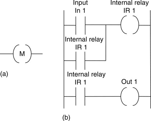
In PLCs there are elements that are used to hold data, that is, bits, and behave like relays, being able to be switched on or off and to switch other devices on or off. Hence the term internal relay. Such internal relays do not exist as real-world switching devices but are merely bits in the storage memory that behave in the same way as relays. For programming, they can be treated in the same way as an external relay output and input. Thus inputs to external switches can be used to give an output from an internal relay. This then results in the internal relay contacts being used, in conjunction with other external input switches, to give an output, such as activating a motor. Thus we might have (Figure 7.1):
On one rung of the program:
Inputs to external inputs activate the internal relay output.
On a later rung of the program:
As a consequence of the internal relay output, internal relay contacts are activated and so control some output.
In using an internal relay, it has to be activated on one rung of a program and then its output used to operate switching contacts on another rung, or rungs, of the program. Internal relays can be programmed with as many sets of associated contacts as desired.
To distinguish internal relay outputs from external relay outputs, they are given different types of addresses. Different manufacturers tend to use different terms for internal relays and have different ways of expressing their addresses. For example, Mitsubishi uses the term auxiliary relay or marker and the notation M100, M101, and so on. Siemens uses the term flag and the notation F0.0, F0.1, and so on. Telemecanique uses the term bit and the notation B0, B1, and so on. Toshiba uses the term internal relay and the notation R000, R001, and so on. Allen-Bradley uses the term bit storage and notation in the PLC-5 of the form B3/001, B3/002, and so on.
7.2 Ladder Programs
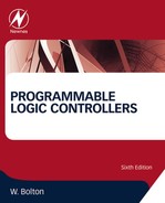
With ladder programs, an internal relay output is represented using the symbol for an output device, namely ( ), with an address that indicates that it is an internal relay. Thus, with a Mitsubishi PLC, we might have the address M100, the M indicating that it is an internal relay or marker rather than an external device. The internal relay switching contacts are designated with the symbol for an input device, namely | |, and given the same address as the internal relay output, such as M100.
7.2.1 Programs with Multiple Input Conditions
As an illustration of the use that can be made of internal relays, consider the following situation. A system is to be activated when two different sets of input conditions are realized. We might just program this as an AND logic gate system; however, if a number of inputs have to be checked in order that each of the input conditions can be realized, it may be simpler to use an internal relay. The first input conditions then are used to give an output to an internal relay. This relay has associated contacts that then become part of the input conditions with the second input.
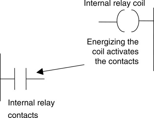
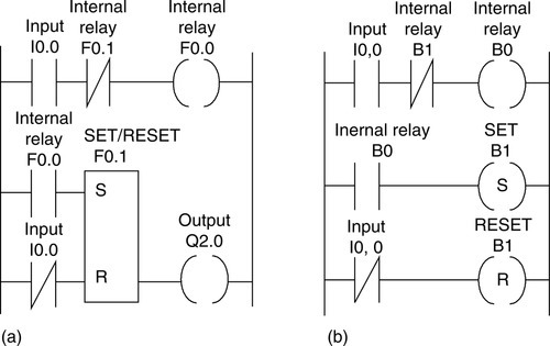
Figure 7.2 shows a ladder program for such a task. For the first rung, when input In 1 or input In 3 is closed and input In 2 closed, internal relay IR 1 is activated. This results in the contacts for IR 1 closing. If input In 4 is then activated, there is an output from output Out 1. Such a task might be involved in the automatic lifting of a barrier when someone approaches from either side. Input In 1 and input In 3 are inputs from photoelectric sensors that detect the presence of a person approaching or leaving from either side of the barrier, input In 1 being activated from one side of it and input In 3 from the other. Input In 2 is an enabling switch to enable the system to be closed down. Thus when input In 1 or input In 3, and input In 2, are activated, there is an output from internal relay 1. This will close the internal relay contacts. If input In 4, perhaps a limit switch, detects that the barrier is closed, then it is activated and closes. The result is then an output from Out 1, a motor that lifts the barrier. If the limit switch detects that the barrier is already open, the person having passed through it, then it opens and so output Out 1 is no longer energized and a counterweight might then close the barrier. The internal relay has enabled two parts of the program to be linked, one part being the detection of the presence of a person and the second part the detection of whether the barrier is already up or down. Figure 7.3a shows how Figure 7.2 would appear in Mitsubishi notation and Figure 7.3b shows how it would appear in Siemens notation.
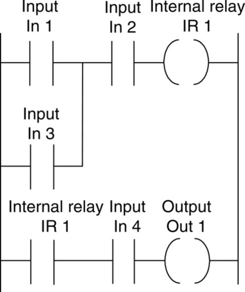
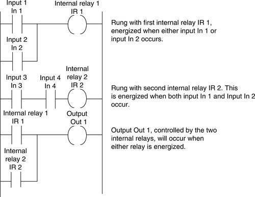
Figure 7.4 is another example of a ladder program involving internal relays. Output 1 is controlled by two input arrangements. The first rung shows the internal relay IR 1, which is energized if input In 1 or In 2 is activated and closed. The second rung shows internal relay IR 2, which is energized if inputs In 3 and In 4 are both energized. The third rung shows that output Out 1 is energized if internal relay IR 1 or IR 2 is activated. Thus there is an output from the system if either of two sets of input conditions is realized.
7.2.2 Latching Programs
Another use of internal relays is for resetting a latch circuit. Figure 7.5 shows an example of such a ladder program.
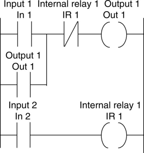
When the input In 1 contacts are momentarily closed, there is an output at Out 1. This closes the contacts for Out 1 and so maintains the output, even when input In 1 opens. When input In 2 is closed, the internal relay IR 1 is energized and so opens the IR 1 contacts, which are normally closed. Thus the output Out 1 is switched off and so the output is unlatched.
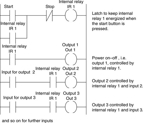
Consider a situation requiring latch circuits where there is an automatic machine that can be started or stopped using push-button switches. A latch circuit is used to start and stop the power being applied to the machine. The machine has several outputs that can be turned on if the power has been turned on and are off if the power is off. It would be possible to devise a ladder diagram that has individually latched controls for each such output. However, a simpler method is to use an internal relay. Figure 7.6 shows such a ladder diagram. The first rung has the latch for keeping the internal relay IR 1 on when the start switch gives a momentary input. The second rung will then switch the power on. The third rung will also switch on and give output Out 2 if the input 2 contacts are closed. The third rung will also switch on and give output Out 3 if the input 3 contacts are closed. Thus all the outputs can be switched on when the start push button is activated. All the outputs will be switched off if the stop switch is opened. Thus all the outputs are latched by IR 1.
7.2.3 Response Time
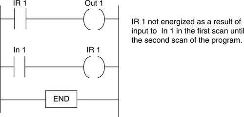
The time taken between an input occurring and an output changing depends on such factors as the electrical response time of the input circuit, the mechanical response of the output device, and the scan time of the program. A ladder program is read from left to right and from top to bottom. Thus if an output device, such as an internal relay, is set in one scan cycle and the output has to be fed back to earlier in the program, it will require a second scan of the program before it can be activated. Figure 7.7 illustrates this concept.
7.3 Battery-Backed Relays
If the power supply is cut off from a PLC while it is being used, all the output relays and internal relays will be turned off. Thus when the power is restored, all the contacts associated with those relays will be set differently from when the power was on. Therefore, if the PLC was in the middle of some sequence of control actions, it would resume at a different point in the sequence. To overcome this problem, some internal relays have battery backup so that they can be used in circuits to ensure a safe shutdown of a plant in the event of a power failure and so enable it to restart in an appropriate manner. Such battery-backed relays retain their state of activation, even when the power supply is off. The relay is said to have been made retentive.
The term retentive memory coil is frequently used for such elements. Figure 7.8a shows the IEC 1131-3 standard symbol for such elements. With Mitsubishi PLCs, battery-backed internal relay circuits use M300 to M377 as addresses for such relays. Other manufacturers use different addresses and methods of achieving retentive memory. The Allen-Bradley PLC-5 uses latch and unlatch rungs. If the relay is latched, it remains latched if power is lost and is unlatched when the unlatch relay is activated. (See Section 7.5 for a discussion of such relays in the context of set and reset coils.)
As an example of the use of such a relay, Figure 7.8b shows a ladder diagram for a system designed to cope with a power failure. IR 1 is a battery-backed internal relay. When input In 1 contacts close, output IR 1 is energized. This closes the IR 1 contacts, latching so that IR 1 remains on even if input In 1 opens. The result is an output from Out 1. If there is a power failure, IR 1 still remains energized and so the IR 1 contacts remain closed and there is an output from Out 1.
7.4 One-Shot Operation
One of the functions provided by some PLC manufacturers is the ability to program an internal relay so that its contacts are activated for just one cycle, that is, one scan through the ladder program. Hence when operated, the internal relay provides a fixed duration pulse at its contacts. This function is often termed one-shot. Though some PLCs have such a function as part of their programs, such a function can also easily be developed with just two rungs of a ladder program. Figure 7.9 shows such a pair of rungs.
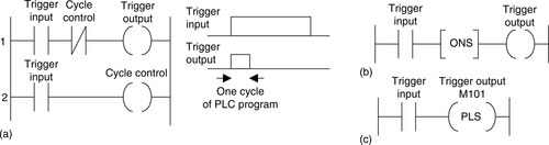
For Figure 7.9a, when the trigger input occurs, it gives a trigger output in rung 1. In rung 2 it gives a cycle control output on an internal relay. Because rung 2 occurs after rung 1, the effect of the cycle control is not felt until the next cycle of the PLC program, when it opens the cycle control contacts in rung 1 and stops the trigger output. The trigger output then remains off, despite there being a trigger input. The trigger output can only occur again when the trigger output is switched off and then switched on again.
Figures 7.9b and 7.9c show the built-in facilities with Allen-Bradley and Mitsubishi PLCs. With the Mitsubishi PLC (Figure 7.9c), the output internal relay—say, M100—is activated when the trigger input—say, X400—contacts close. Under normal circumstances, M100 would remain on for as long as the X400 contacts were closed. However, if M100 has been programmed for pulse operation, M100 only remains on for a fixed period of time—one program cycle. It then goes off, regardless of X400 being on. The programming instructions that would be used are LD X400, PLS M100. The preceding represents pulse operation when the input goes from off to on, that is, is positive-going. If, in Figure 7.9c, the trigger input is made normally closed rather than normally open, the pulse occurs when the input goes from on to off—in other words, is negative-going.
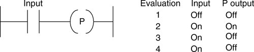
The IEC 61131-3 gives standards for the symbols for positive transition-sensing and negative transition-sensing coils (Figure 7.10).

With the positive transition-sensing coil, if the power flow to it changes from off to on, the output is set on for one ladder rung evaluation. With the negative transition-sensing coil, if the power to it changes from off to on, the output is set on for one ladder rung evaluation. Thus, for the ladder rung of Figure 7.11, with the input off there is no output. When the input switches on, there is an output from the coil. However, the next and successive cycles of the program do not give outputs from the coil even though the switch remains on. The coil only gives an output the first time the switch is on.
7.5 Set and Reset
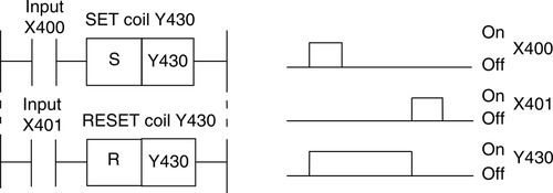
Another function that is often available is the ability to set and reset an internal relay. The set instruction causes the relay to self-hold, that is, latch. It then remains in that condition until the reset instruction is received. The term flip-flop is often used. Figure 7.12 shows the IEC 61131-3 standards for such coils. The SET coil is switched on when power is supplied to it and remains set until it is RESET. The RESET coil is reset to the off state when power is supplied to it and remains off until it is SET.
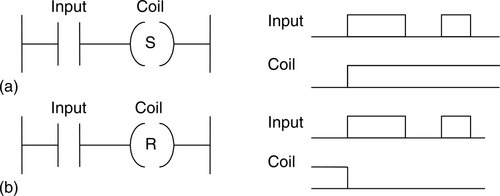
Figure 7.13 shows an example of a ladder diagram involving such a function. Activation of the first input, X400, causes the output Y430 to be turned on and set, that is, latched. Thus if the first input is turned off, the output remains on. Activation of the second input, X401, causes the output Y430 to be reset, that is, turned off and latched off. Thus the output Y430 is on for the time between X400 being momentarily switched on and X401 being momentarily switched on. Between the two rungs indicated for the set and reset operations, there could be other rungs for other activities to be carried out, with the set rung switching on an output at the beginning of the sequence and off at the end.
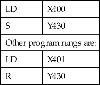
The programming instructions for the ladder rungs in the program for Figure 7.13 are:
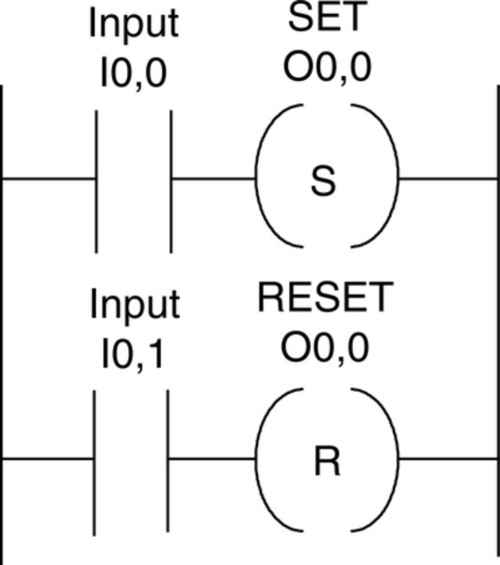
With a Telemecanique PLC, the ladder diagram would be as shown in Figure 7.14 and the programming instructions would be:
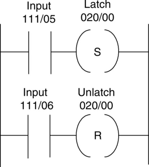
With an Allen-Bradley PLC, the terms latch and unlatch are used. Figure 7.15 shows the ladder diagram.
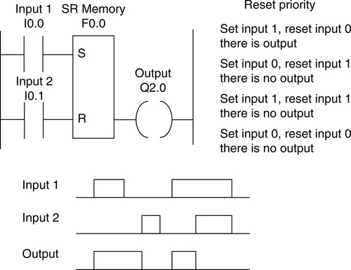
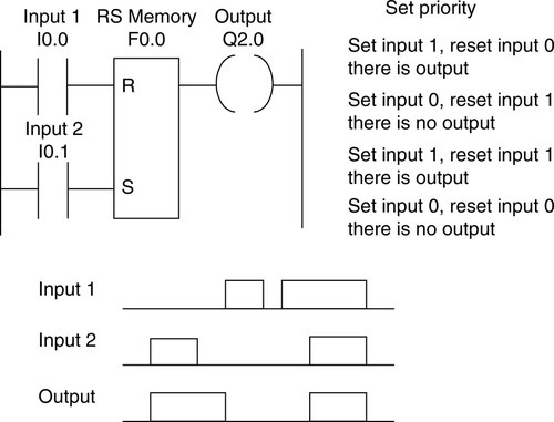
The SET and RESET coil symbols are often combined in a single box symbol. Figure 7.16 shows the equivalent ladder diagram for the set-reset function in the preceding figures with a Siemens PLC. The term memory box is used by them for the SET/RESET box, and the box shown is termed an SR or reset priority memory function in that reset has priority. With set priority (RS memory box), the arrangement is as shown in Figure 7.17. The programming instructions (F indicates an internal relay) for reset priority are:
Toshiba uses the term flip-flop, and Figure 7.18 shows the ladder diagram.
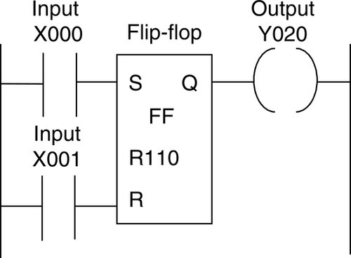
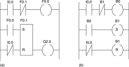
Figure 7.19 shows how the set-reset function can be used to build the pulse (one-shot) function described in the previous section. Figure 7.19a shows it for a Siemens PLC (F indicates internal relay) and Figure 7.19b for a Telemecanique PLC (B indicates internal relay). In Figures 7.19a and 7.19b, an input (I0.0, I0,0) causes the internal relay (B0, F0.0) in the first rung to be activated. This results in the second rung, in the set/reset internal relay being set. This setting action results in the internal relay (F0.1, B1) in the first rung opening, and so, despite there being an input in the first rung, the internal relay (BO, F0.0) opens. However, because the rungs are scanned in sequence from top to bottom, a full cycle must elapse before the internal relay in the first rung opens. A pulse of duration one cycle has thus been produced. The system is reset when the input (I0.0, I0,0) ceases.
7.5.1 Program Examples
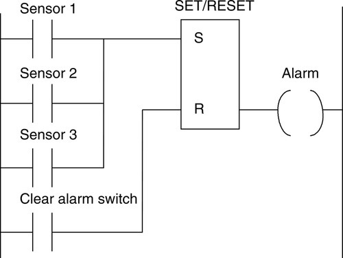
An example of the basic elements of a simple program for use with a fire alarm system is shown in Figure 7.20. Fire sensors provide inputs to a SET/RESET function block so that if one of the sensors is activated, the alarm is set and remains set until it is cleared by being reset. When set it sets off the alarm.
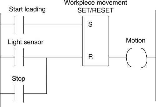
Another example showing the basic elements of a program is shown in Figure 7.21. This could be used with a system designed to detect when a workpiece has been loaded into the correct position for some further operation. When the start contacts are closed, the output causes the workpiece to move. This continues until a light beam is interrupted and resets, causing the output to cease. A stop button is available to stop the movement at any time.
7.6 Master Control Relay
When large numbers of outputs have to be controlled, it is sometimes necessary for whole sections of ladder diagrams to be turned on or off when certain criteria are realized. This could be achieved by including the contacts of the same internal relay in each of the rungs so that its operation affects all of them. An alternative is to use a master control relay. Figure 7.22 illustrates the use of such a relay to control a section of a ladder program.
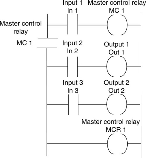
With no input to input In 1, the output internal relay MC 1 is not energized, and so its contacts are open. This means that all the rungs between where it is designated to operate and the rung on which its reset MCR or another master control relay is located are switched off. Assuming that it is designated to operate from its own rung, we can imagine it to be located in the power line in the position shown, and so rungs 2 and 3 are off. When input In 1 contacts close, the master relay MC 1 is energized. When this happens, all the rungs between it and the rung with its reset MCR 1 are switched on. Thus outputs Out 1 and Out 2 cannot be switched on by inputs In 2 and In 3 until the master control relay has been switched on. The master control relay MC 1 acts only over the region between the rung it is designated to operate from and the rung on which MCR 1 is located.
With a Mitsubishi PLC, an internal relay can be designated as a master control relay by programming it accordingly. Thus to program an internal relay M100 to act as a master control relay, the program instruction is:
To program the resetting of that relay, the program instruction is:
Thus for the ladder diagram shown in Figure 7.23, which is Figure 7.22 with Mitsubishi addresses, the program instructions are:
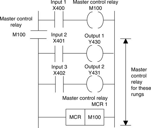
Figure 7.24 shows the format used by Allen-Bradley. To end the control of one master control relay (MCR), a second master control relay (MCR) is used with no contacts or logic preceding it. It is said to be programmed unconditionally.
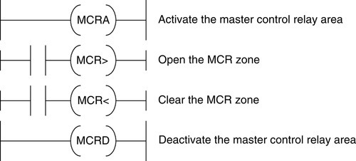
The representation used for MCRs in Siemens ladder programs is shown in Figure 7.25. An area in which an MCR is to operate is defined by the activate master control area and deactivate master control relay functions. Within that area, the MCR is enabled when the MCR> coil is activated and disabled when the MCR< coil is enabled.
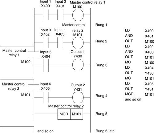
A program might use a number of MCRs, enabling various sections of a ladder program to be switched in or out. Figure 7.26 shows a ladder program in Mitsubishi format involving two MCRs. With M100 switched on but M101 off, the sequence is: rungs 1, 3, 4, 6, and so on. The end of the M100 controlled section is indicated by the occurrence of the other MCR, M101. With M101 switched on but M100 off, the sequence is: rungs 2, 4, 5, 6, and so on. The end of this section is indicated by the presence of the reset. This reset has to be used since the rung is not followed immediately by another MCR. Such an arrangement could be used to switch on one set of ladder rungs if one type of input occurs and another set of ladder rungs if a different input occurs.
7.6.1 Examples of Programs
The following looks at a program that illustrates the uses of MCRs. The program is being developed for use with a pneumatic valve system involving the movement of pistons in cylinders to give a particular sequence of piston actions. First, however, we show how latching might be used with such systems to maintain actions.
Consider a pneumatic system with single-solenoid controlled valves and involving two cylinders A and B with limit switches a–, a+, b–, b+ detecting the limits of the piston rod movements (Figure 7.27), with the requirement to give the sequence A+, B+, A–, B–. Figure 7.28 shows the ladder diagram that can be used.
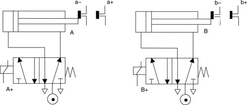
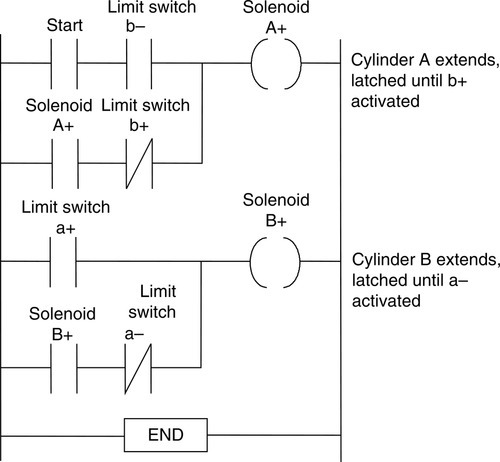
The solenoid A+ is energized when the start switch and limit switch b– are closed. This provides latching to keep A+ energized as long as the normally closed contacts for limit switch b+ are not activated. When limit switch a+ is activated, solenoid B+ is energized. This provides latching that keeps B+ energized as long as the normally closed contacts for limit switch a– are not activated. When cylinder B extends, the limit switch b+ opens its normally closed contacts and unlatches the solenoid A+. Solenoid A thus retracts. When it has retracted and opened the normally closed contacts a–, solenoid B+ becomes unlatched and cylinder B retracts.
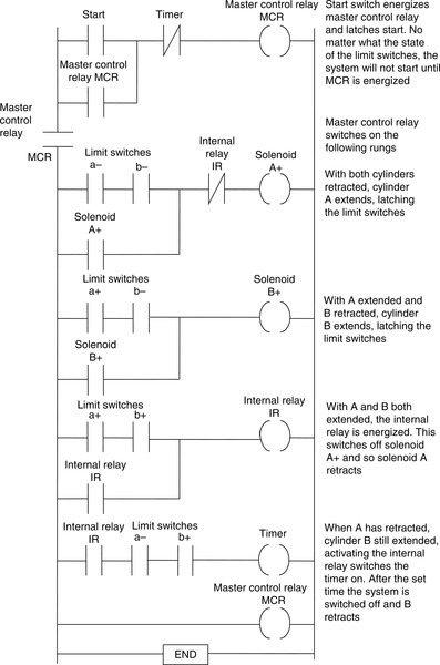
Now consider the ladder program that could be used with the pair of single-solenoid-controlled cylinders in Figure 7.27 to give, when and only when the start switch is momentarily triggered, the sequence A+, B+, A–, then a 10 s time delay, B–, and stop at that point until the start switch is triggered again. Figure 7.29 shows how such a program can be devised using a MCR. The MCR is activated by the start switch and remains on until switched off by the rung containing just MCR. (See Chapter 9 for a discussion of timers.)
Summary
In PLCs, elements that are used to hold data, that is, bits, and behave like relays and so are able to switch on or off other devices are termed internal relays (or alternately auxiliary relays, markers, flags, or bit storage elements). With ladder programs, an internal relay output is represented using the symbol for an output device, namely ( ), with an address that indicates that it is an internal relay. The internal relay switching contacts are designated with the symbol for an input device, namely | |, and given the same address as the internal relay output. Internal relays that are battery-backed are able to retain their setting, even when the power is removed. The relay is said to be retentive.
One of the functions provided by some PLC manufacturers is the ability to program an internal relay so that its contacts are activated for just one cycle. This function is termed one-shot. Another function that is often available is the ability to set and reset an internal relay, for which the term flip-flop is used.
A MCR is able to turn on or off a section of a ladder program up to the point at which the master control relay is reset.
Problems
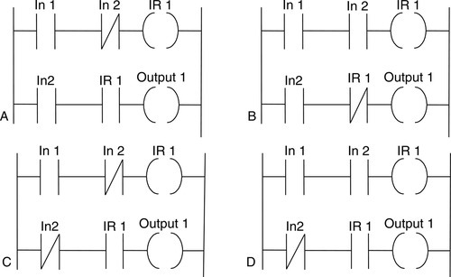
Problems 1 through 23 have four answer options: A, B, C, or D. Choose the correct answer from the answer options. Problems 1 through 3 refer to Figure 7.30, which shows a ladder diagram with an internal relay (designated IR 1), two inputs (In 1 and In 2), and an output (Output 1).
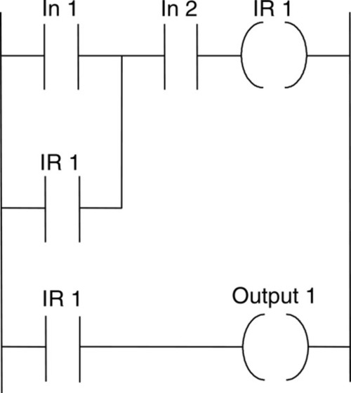
1. Decide whether each of these statements is true (T) or false (F). For the ladder diagram shown in Figure 7.30, there is an output from output 1 when:
(i) There is just an input to In 1.
(ii) There is just an input to In 2.
A. (i) T (ii) T
B. (i) T (ii) F
C. (i) F (ii) T
D. (i) F (ii) F
2. Decide whether each of these statements is true (T) or false (F). For the ladder diagram shown in Figure 7.30, there is an output from output 1 when:
(i) There is an input to In 2 and a momentary input to In 1.
(ii) There is an input to In 1 or an input to In 2.
A. (i) T (ii) T
B. (i) T (ii) F
C. (i) F (ii) T
D. (i) F (ii) F
3. Decide whether each of these statements is true (T) or false (F). For the ladder diagram shown in Figure 7.30, the internal relay:
(i) Switches on when there is just an input to In 1.
(ii) Switches on when there is an input to In 1 and to In 2.
A. (i) T (ii) T
B. (i) T (ii) F
C. (i) F (ii) T
D. (i) F (ii) F
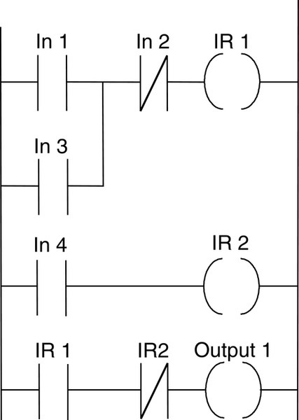
Problems 4 through 6 refer to Figure 7.31, which shows a ladder diagram involving internal relays IR 1 and IR 2, inputs In 1, In 2, In 3, and In 4, and output Output 1.
4. Decide whether each of these statements is true (T) or false (F). For the ladder diagram shown in Figure 7.31, the internal relay IR 1 is energized when:
(i) There is an input to In 1.
(ii) There is an input to In 3.
A. (i) T (ii) T
B. (i) T (ii) F
C. (i) F (ii) T
D. (i) F (ii) F
5. Decide whether each of these statements is true (T) or false (F). For the ladder diagram shown in Figure 7.31, the internal relay IR 2 is energized when:
(i) Internal relay IR 1 is energized.
(ii) Input 4 is energized.
A. (i) T (ii) T
B. (i) T (ii) F
C. (i) F (ii) T
D. (i) F (ii) F
6. Decide whether each of these statements is true (T) or false (F). For the ladder diagram shown in Figure 7.31, there is an output from Output 1 when:
(i) There are inputs to only In 1, In 2, and In 4.
(ii) There are inputs to only In 3 and In 4.
A. (i) T (ii) T
B. (i) T (ii) F
C. (i) F (ii) T
D. (i) F (ii) F
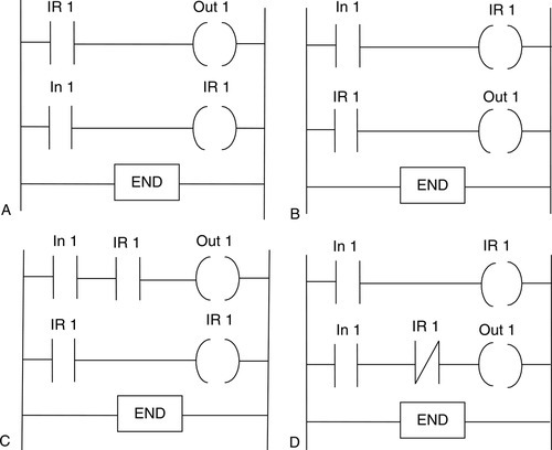
7. Which one of the programs in Figure 7.32 can obtain an output from Out 1 when just input In 1 occurs?
8. Which one of the programs in Figure 7.33 will give an output from Out 1 in the same program scan as there is an input to In 1?
Problems 9 and 10 refer to Figure 7.34, which shows a ladder diagram involving a battery-backed relay IR 1, two inputs (In 1 and In 2), and an output (Output 1).
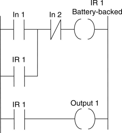
9. Decide whether each of these statements is true (T) or false (F). For the ladder diagram shown in Figure 7.34, there is an output from Output 1 when:
(i) There is a short duration input to In 1.
(ii) There is no input to In 2.
A. (i) T (ii) T
B. (i) T (ii) F
C. (i) F (ii) T
D. (i) F (ii) F
10. Decide whether each of these statements is true (T) or false (F). For the ladder diagram shown in Figure 7.34:
(i) The input In 1 is latched by the internal relay so that the internal relay IR 1 remains energized, even when the input In 1 ceases.
(ii) Because the internal relay IR 1 is battery-backed, once there is an output from Output 1, it will continue, even when the power is switched off, until there is an input to In 2.
A. (i) T (ii) T
B. (i) T (ii) F
C. (i) F (ii) T
D. (i) F (ii) F
11. When the program instructions LD X100, PLS M400 are used for a ladder rung, the internal relay M400 will:
A. Remain on even when the input to X100 ceases
B. Remain closed unless there is a pulse input to X100
C. Remain on for one program cycle when there is an input to X100
D. Remain closed for one program cycle after an input to X100
12. When the program instructions LDI X100, PLS M400 are used for a ladder rung, the internal relay M400 will:
A. Remain on when the input to X100 ceases
B. Remain on when there is a pulse input to X100
C. Remain on for one program cycle when there is an input to X100
D. Remain on for one program cycle after the input to X100 ceases
13. A Mitsubishi ladder program has the program instructions LD X100, S M200, LD X101, R M200, followed by other instructions for further rungs. There is the following sequence: an input to the input X100, the input to X100 ceases, some time elapses, an input to the input X101, the input to X101 ceases, followed by inputs to later rungs. The internal relay M200 will remain on:
A. For one program cycle from the start of the input to X100
B. From the start of the input to X100 to the start of the input to X101
C. From the start of the input to X100 to the end of the input to X101
D. From the end of the input to X100 to the end of the input to X101
14. A Siemens ladder program has the program instructions A I0.0, S F0.0, A I0.1, R F0.0, A F0.0, = Q2.0, followed by other instructions for further rungs. There is the sequence: an input to input I0.0, the input to I0.0 ceases, some time elapses, an input to input I0.1, the input to I0.1 ceases, followed by inputs to later rungs. The internal relay F0.0 will remain on:
A. For one program cycle from the start of the input to I0.0
B. From the start of the input to I0.0 to the start of the input to I0.1
C. From the start of the input to I0.0 to the end of the input to I0.1
D. From the end of the input to I0.0 to the end of the input to I0.1
15. A Telemecanique ladder program has the program instructions L I0,0, S O0,0, L I0,1, R O0,0, followed by other instructions for further rungs. There is the following sequence: an input to input I0,0, the input to I0,0 ceases, some time elapses, an input to input I0,1, the input to I0,1 ceases, followed by inputs to later rungs. The internal relay O0,0 will remain on:
A. For one program cycle from the start of the input to I0,0
B. From the start of the input to I0,0 to the start of the input to I0,1
C. From the start of the input to I0,0 to the end of the input to I0,1
D. From the end of the input to I0,0 to the end of the input to I0,1
16. An output is required from output Y430 that lasts for one cycle after an input to X100 starts. This can be given by a ladder program with the instructions:
B. LD X100, M100, LD M100, Y430
C. LD X100, PLS M100, LD M100, Y430
D. LD X400, PLS M100, LDI M100, Y430
Problems 17 and 18 refer to Figure 7.35, which shows two versions of the same ladder diagram according to two different PLC manufacturers. In Figure 7.35a, which uses Siemens notation, I is used for inputs, F for internal relays, and Q for the output. In Figure 7.35b, which uses Telemecanique notation, I is used for inputs and B for internal relays.
17. For the ladder diagram shown in Figure 7.35a, when there is an input to I0.0, the output Q2.0:
A. Comes on and remains on for one cycle.
B. Comes on and remains on.
C. Goes off and remains off for one cycle.
D. Goes off and remains off.
18. For the ladder diagram shown in Figure 7.35b, when there is an input to I0,0, the internal relay B1:
A. Comes on and remains on for one cycle.
B. Comes on and remains on.
C. Goes off and remains off for one cycle.
D. Goes off and remains off.
Problems 19 and 20 refer to Figure 7.36, which shows a Toshiba ladder program with inputs X000, X001, and X002, an output Y020, and a flip-flop R110.
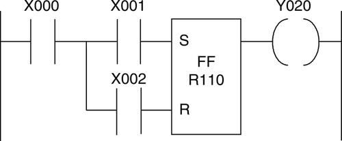
19. Decide whether each of these statements is true (T) or false (F). For there to be an output from Y020, there must be an input to:
(ii) X001.
A. (i) T (ii) T
B. (i) T (ii) F
C. (i) F (ii) T
D. (i) F (ii) F
20. Decide whether each of these statements is true (T) or false (F). With an input to X000, then:
(i) An input to X001 causes the output to come on.
(ii) An input to X002 causes the output to come on.
A. (i) T (ii) T
B. (i) T (ii) F
C. (i) F (ii) T
D. (i) F (ii) F
21. Decide whether each of these statements is true (T) or false (F). A master control relay can be used to:
(i) Turn on a section of a program when certain criteria are met.
(ii) Turn off a section of a program when certain criteria are not met.
A. (i) T (ii) T
B. (i) T (ii) F
C. (i) F (ii) T
D. (i) F (ii) F
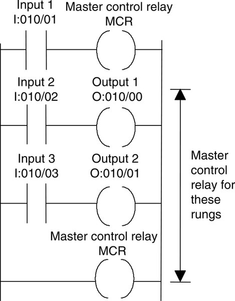
Problems 22 and 23 refer to Figure 7.37, which shows a ladder program in Allen-Bradley format.
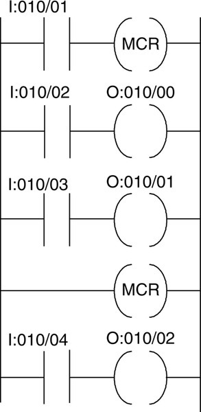
22. Decide whether each of these statements is true (T) or false (F). When there is an input to I:010/01:
(i) An input to I:010/02 gives an output from O:010/00.
(ii) An input to I:010/03 gives an output from O:010/01.
A. (i) T (ii) T
B. (i) T (ii) F
C. (i) F (ii) T
D. (i) F (ii) F
23. Decide whether each of these statements is true (T) or false (F). When there is no input to I:010/01:
(i) An input to I:010/02 gives no output from O:010/00.
(ii) An input to I:010/04 gives no output from O:010/02.
A. (i) T (ii) T
B. (i) T (ii) F
C. (i) F (ii) T
D. (i) F (ii) F
24. Devise ladder programs that can be used to:
(a) Maintain an output on, even when the input ceases and when there is a power failure
(b) Switch on an output for a time of one cycle following a brief input
(c) Switch on the power to a set of rungs