Jump and Call
This chapter considers the jump instruction, which enables part of a program to be jumped over, and the way in which subroutines in ladder programs can be called up. Subroutines enable commonly occurring operations in a program to be repeatedly called up and used over again.
8.1 Jump
A function often provided with PLCs is the conditional jump. We can describe this as:
IF (some condition occurs) THEN
 perform some instructions
ELSE
 perform some other instructions
Such a facility enables programs to be designed such that if certain conditions are met, certain events occur, and if they are not met, other events occur. Thus, for example, we might need to design a system so that if the temperature is above 60°C a fan is switched on, and if below that temperature no action occurs.
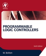
Thus, if the appropriate conditions are met, this function enables part of a ladder program to be jumped over. Figure 8.1 illustrates this concept in a general manner. When there is an input to Input 1, its contacts close and there is an output to the jump relay. This then results in the program jumping to the rung in which the jump end occurs and skipping the intermediate program rungs. Thus, in this case, when there is an input to Input 1, the program jumps to rung 4 and then proceeds with rungs 5, 6, and so on. When there is no input to Input 1, the jump relay is not energized and the program then proceeds to rungs 2, 3, and so on.
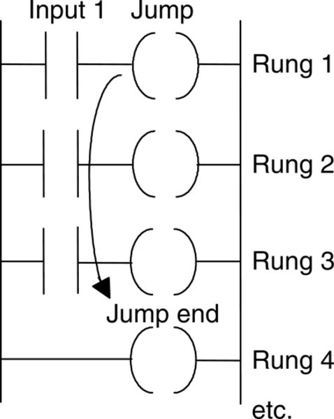
Figure 8.2a shows the preceding ladder program in the form used by Mitsubishi. The jump instruction is denoted by conditional jump (CJP) and the place to which the jump occurs is denoted by end of jump (EJP). The condition that the jump will occur is that there is an input to X400. When that happens, the rungs involving inputs X401 and X403 are ignored and the program jumps to continue with the rungs following the end-jump instruction with the same number as the start-jump instruction—in this case, EJP 700.
With the Allen-Bradley PLC-5 format, the jump takes place from the jump instruction (JMP) to the label instruction (LBL). The JMP instruction is given a three-digit number from 000 to 255 and the LBL instruction the same number. Figure 8.2b shows a ladder program in this format.
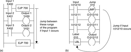
With Siemens' programs, conditional jumps are represented as shown in Figure 8.3, there being a jump instruction JMP that is executed if the input is a 1 and another jump instruction JMPN that is executed if the input is 0. The end of both instructions is the label DEST.
8.1.1 Jumps Within Jumps
Jumps within jumps are possible. For example, we might have the situation shown in Figure 8.4. If the condition for jump instruction 1 is realized, the program jumps to rung 8. If the condition is not met, the program continues to rung 3. If the condition for jump instruction 2 is realized, the program jumps to rung 6. If the condition is not met, the program continues through the rungs.
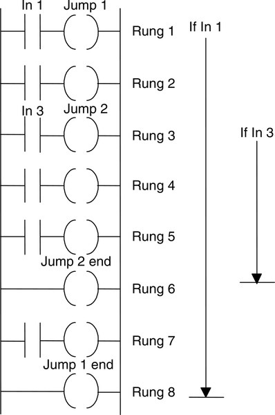
Thus if we have an input to In 1, the rung sequence is rung 1, 8, and so on. If we have no input to In 1 but we have an input to In 3, the rung sequence is 1, 2, 6, 7, 8, and so on. If we have no input to In 1 and no input to In 3, the rung sequence is 1, 2, 3, 4, 5, 6, 7, 8, and so on. The jump instruction enables different groups of program rungs to be selected, depending on the conditions occurring.
8.2 Subroutines
Subroutines are small programs to perform specific tasks that can be called for use in larger programs. The advantage of using subroutines is that they can be called repetitively to perform specific tasks without having to be written out in full in the larger program. Thus with a Mitsubishi program we might have the situation shown in Figure 8.5a. When input 1 occurs, the subroutine P is called. This is then executed, the instruction SRET indicating its end and the point at which the program returns to the main program.

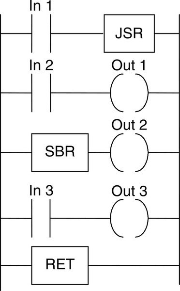
With Allen-Bradley, subroutines are called by using a jump-to-subroutine (JSR) instruction, the start of the subroutine being indicated by SBR and its end and point of return to the main program by RET (Figure 8.5b). With other PLC manufacturers a similar format can be adopted; they might use CALL to call up a subroutine block and RET to indicate the return instruction to the main program.
8.2.1 Function Boxes
A function box approach can be used with programs and is particularly useful where there is a library of subroutine functions to be called. A function box is defined as being part of a program that is packaged so that it can be used a number of times in different parts of the same program or different programs. Using such boxes enables programs to be constructed from smaller, more manageable blocks. Each function box has input and output for connection to the main program, is able to store values, and contains a piece of program code that runs every time the box is used, processing the input to give the output. PLC manufacturers supply a number of function boxes that can be used within programs.
Figure 8.6a shows the form of a standard function box, such as an on-delay timer (see Chapter 9). When input IN goes to 1, output Q follows and remains 1 for the time duration set by input PT.
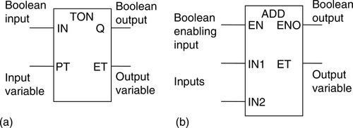
It is possible to control when a function box (Figure 8.6b), such as a function box to add two inputs, operates by using a special input called EN (enable). When EN is set to 1, the function is executed. If EN is set to 0, the function remains dormant and does not assign a value to its output. Such function boxes have an ENO output that is set to 1 when the function execution is successfully completed.
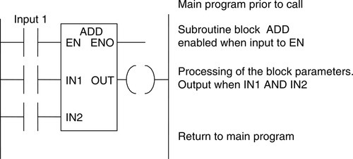
If the EN (enable) block input is connected directly to the left power rail, the call is without conditions and is always executed. If there is a logic operation preceding EN, the block call is executed only if the logic condition is fulfilled. In Figure 8.7 this is a closure of contacts of Input 1. Several blocks can be connected in series by connecting the ENO (enable output) of one to the EN input of the next.
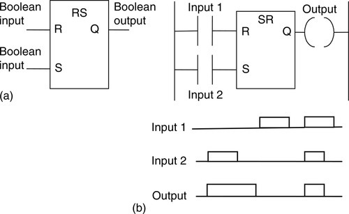
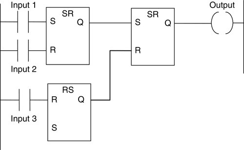
As an illustration of a standard function block, consider the SR box (a bistable that is a latch described in Section 3.8; see Figure 8.8a).
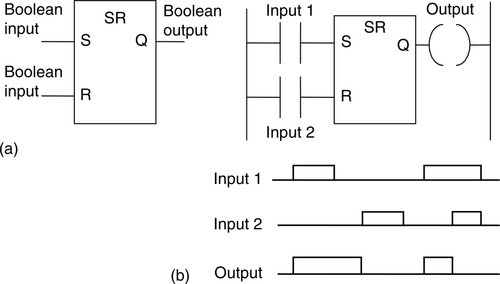
If the set input S has an input of 1 and the rest input R a 0, there is an output of 1 at Q and the block “remembers” this state until it is reset. If the set and reset signals are both 1, the output is 1. The “memory” is reset if there is a 1 input at reset R and a 0 at the set S input. Figure 8.8b shows such a block in a ladder program.
As a further illustration, Figure 8.9 shows the RS function block (a bistable latch). There is an output of 1 when the set input is 1; this then goes to 0 when reset is 1. If the set and reset inputs are both 1, the output is 0.
Other commonly used function boxes are discussed in the following chapters.
Summary
A function often provided with PLCs is the conditional jump. We can describe this as follows: IF (some condition occurs) THEN perform some instructions, ELSE perform some other instructions.
Subroutines are small programs to perform specific tasks that can be called for use in larger programs. The advantage of using subroutines is that they can be called repetitively to perform specific tasks without having to be written in full in the larger program. A function box approach can be used with programs and is particularly useful where there is a library of subroutine functions to be called. A function box is defined as being part of a program that is packaged so that it can be used a number of times in different parts of the same program or different programs. Using such boxes enables programs to be constructed from smaller, more manageable blocks. Each function box has input and output for connection to the main program, is able to store values, and contains a piece of program code that runs every time the box is used, processing the input to give the output. PLC manufacturers supply a number of function boxes that can be used within programs.
Problems
Problems 1 through 6 have four answer options: A, B, C, or D. Choose the correct answer from the answer options. Problems 1 and 2 refer to Figure 8.10, which shows a ladder diagram with inputs In 1, In 2, In 3, and In 4; outputs Out 1, Out 2, Out 3, and Out 4; and a jump instruction.
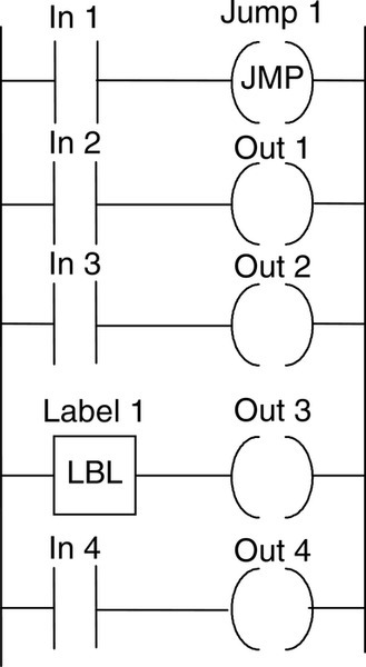
1. For the ladder diagram shown in Figure 8.10, for output Out 1 to occur:
B. Both inputs In 1 and In 2 must occur
C. Input In 1 must not occur and input 2 must occur
D. Both inputs In 1 and In 2 must not occur
2. Decide whether each of these statements is true (T) or false (F). For the ladder diagram shown in Figure 8.10, following input In 1:
(ii) Output Out 3 occurs.
A. (i) T (ii) T
B. (i) T (ii) F
C. (i) F (ii) T
D. (i) F (ii) F
Problems 3 and 4 refer to Figure 8.11, which shows a ladder diagram with inputs (In 1, In 2, and In 3), outputs (Out 1, Out 2, and Out 3), and a jump-to-subroutine instruction.
3. Decide whether each of these statements is true (T) or false (F). For the ladder diagram shown in Figure 8.11:
(i) After input In 1 occurs output Out 2 occurs.
(ii) After output Out 3 occurs the program waits for input In 2 before proceeding
A. (i) T (ii) T
B. (i) T (ii) F
C. (i) F (ii) T
D. (i) F (ii) F
4. Decide whether each of these statements is true (T) or false (F). For the ladder diagram shown in Figure 8.11:
(i) When input In 2 occurs, outputs Out 1 and Out 2 occur.
(ii) When input In 3 occurs, output Out 3 occurs.
A. (i) T (ii) T
B. (i) T (ii) F
C. (i) F (ii) T
D. (i) F (ii) F
5. Decide whether each of these statements is true (T) or false (F). For the program shown in Figure 8.12, there is an output:
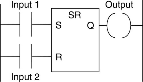
(i) When input 1 is 1 and input 2 is 0.
(ii) When input 1 is 1 and input 2 is 1.
A. (i) T (ii) T
B. (i) T (ii) F
C. (i) F (ii) T
D. (i) F (ii) F
6. Decide whether each of these statements is true (T) or false (F). For the program shown in Figure 8.13, there is an output:
(i) When input 1 is 1, input 2 is 0 and input 3 is 1.
(ii) When input 1 is 0, input 2 is 1 and input 3 is 0.
A. (i) T (ii) T
B. (i) T (ii) F
C. (i) F (ii) T
D. (i) F (ii) F
7. A production plant program requires the following operations to be repeated a number of times: filling a vat, heating the liquid in the vat, and then, when the liquid is at the required temperature, emptying it. Explain how this procedure could be programmed using subroutines.
Lookup Tasks
8. For a particular PLC, determine what function boxes are available.
9. For a particular PLC, determine the programming method to be used to call up a subroutine.