
Timers
In many control tasks there is a need to control time. For example, a motor or a pump might need to be controlled to operate for a particular interval of time or perhaps be switched on after some time interval. PLCs thus have timers as built-in devices. Timers count seconds or fractions of seconds using the internal CPU clock. This chapter shows how such timer function blocks can be programmed to carry out control tasks.
9.1 Types of Timers
PLC manufacturers differ on how timers should be programmed and hence how they can be considered. A common approach is to consider timers to behave like relays with coils that when energized, result in the closure or opening of contacts after some preset time. The timer is thus treated as an output for a rung, with control being exercised over pairs of contacts elsewhere (Figure 9.1a). This is the predominant approach used in this book. Some treat a timer as a delay block that when inserted in a rung, delays signals in that rung from reaching the output (Figure 9.1b).
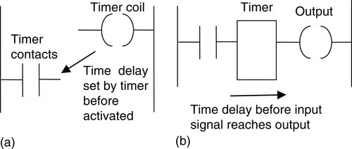
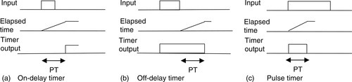
There are a number of different forms of timers that can be found with PLCs: on-delay, off-delay, and pulse. With small PLCs there is likely to be just one form, the on-delay timers. Figure 9.2 shows the IEC symbols. TON is used to denote on-delay, TOF off-delay, and TP pulse timers. On-delay is also represented by T−0 and off-delay by 0−T.

On-delay timers (TON) come on after a particular time delay (Figure 9.3a). Thus as the input goes from 0 to 1, the elapsed time starts to increase, and when it reaches the time specified by the input PT, the output goes to 1. An off-delay timer (TOF) is on for a fixed period of time before turning off (Figure 9.3b). The timer starts when the input signal changes from 1 to 0. Another type of timer is the pulse timer (TP). This timer gives an output of 1 for a fixed period of time (Figure 9.3c), starting when the input goes from 0 to 1 and switching back to 0 when the set time PT has elapsed.
The time duration for which a timer has been set is termed the preset and is set in multiples of the time base used. Some time bases are typically 10 ms, 100 ms, 1 s, 10 s, and 100 s. Thus a preset value of 5 with a time base of 100 ms is a time of 500 ms. For convenience, where timers are involved in this text, a time base of 1 s has been used.
9.2 On-Delay Timers
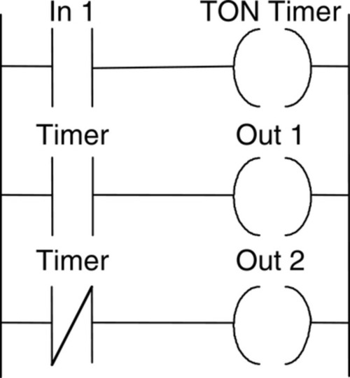
All PLCs generally have on-delay timers; small PLCs possibly have only this type of timer. Figure 9.4a shows a ladder rung diagram involving a on-delay timer. Figure 9.4a is typical of Mitsubishi. The timer is like a relay with a coil that is energized when input In 1 occurs (rung 1). It then closes, after some preset time delay, its contacts on rung 2. Thus the output occurs some preset time after input In 1 occurs. Figure 9.4b, an example of a possible Siemens setup, shows the timer to be a delay item in a rung, rather than a relay. When the signal at the timer's start input changes from 0 to 1, the timer starts and runs for the programmed duration, giving its output then to the output coil. The time value (TV) output can be used to ascertain the amount of time remaining at any instant. A signal input of 1 at the reset input resets the timer whether it is running or not. Techniques for the entry of preset time values vary. Often it requires the entry of a constant K command followed by the time interval in multiples of the time base used. Figures 9.4c, 9.4d, and 9.4e show ladder diagrams for Telemecanique, Toshiba, and Allen-Bradley, respectively. The Allen-Bradley timer symbol shows the type of timer concerned, the timer address, and the time base that indicates the increments by which the timer moves to the preset value, such as 0.001 s, 0.01 s, 0.1 s or 1 s. The preset value (PRE) is the number of time increments that the timer must accumulate to reach the required time delay, and the accumulator (ACC) indicates the number of increments that the timer has accumulated while the timer is active and is reset to zero when the timer is reset (useful if a program needs to record how long a particular operation took). The Allen-Bradley timers have three Boolean bits for ladder logic control: a timer enable bit (EN), which goes on when the timer accumulator is incrementing, a timer done bit (DN), which goes on after the set time delay, and a timer timing bit (TT) that is on when the accumulator is incrementing and remains on until the accumulator reaches the preset value.
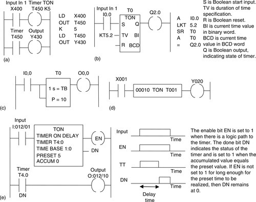
All the programs shown in Figure 9.4 turn on the output device after a set time delay from when there is an input.
9.2.1 Sequencing
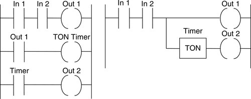
As an illustration of the use of a TON timer, consider the ladder diagram shown in Figure 9.5a. When the input In 1 is on, the output Out 1 is switched on. The contacts associated with this output then start the timer. The contacts of the timer will close after the preset time delay, in this case 5.5 s. When this happens, output Out 2 is switched on. Thus, following the input In 1, Out 1 is switched on and followed 5.5 s later by Out 2. This illustrates how a timed sequence of outputs can be achieved. Figure 9.5b shows the same operation with the format used by the PLC manufacturer in which the timer institutes a signal delay. Figure 9.6c shows the timing diagram.
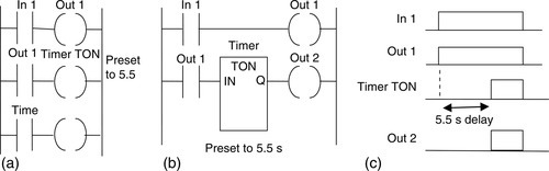
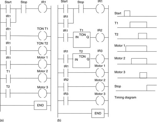
Figure 9.6 shows two versions of how timers can be used to start three outputs, such as three motors, in sequence following a single start button being pressed. In Figure 9.6a, the timers are programmed as coils, whereas in Figure 9.6b, they are programmed as delays. When the start push button is pressed, there is an output from internal relay IR1. This latches the start input. It also starts both timers, T1 and T2, and motor 1. When the preset time for timer 1 has elapsed, its contacts close and motor 2 starts. When the preset time for timer 2 has elapsed, its contacts close and motor 3 starts. The three motors are all stopped by pressing the stop push button. Since this is seen as a complete program, the end instruction has been used.
9.2.2 Cascaded Timers
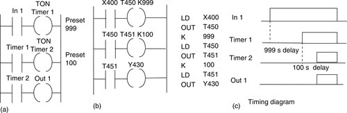
Timers can be linked together (the term cascaded is used) to give longer delay times than are possible with just one timer. Figure 9.7a shows the ladder diagram for such an arrangement. Thus we might have timer 1 with a delay time of 999 s. This timer is started when there is an input to In 1. When the 999 s is up, the contacts for timer 1 close. This then starts timer 2. This has a delay of 100 s. When this time is up, the timer 2 contacts close and there is an output from Out 1. Thus the output occurs 1099 s after the input to In 1 started. Figure 9.7b shows the Mitsubishi version of this ladder diagram with TON timers and the program instructions for that ladder.
9.2.3 On/Off Cycle Timer
Figure 9.8 shows how on-delay timers can be used to produce an on/off cycle timer. The timer is designed to switch on an output for 5 s, then off for 5 s, then on for 5 s, then off for 5 s, and so on. When there is an input to In 1 and its contacts close, timer 1 starts. Timer 1 is set for a delay of 5 s. After 5 s, it switches on timer 2 and the output Out 1. Timer 2 has a delay of 5 s. After 5 s, the contacts for timer 2, which are normally closed, open. This results in timer 1 in the first rung being switched off. This then causes its contacts in the second rung to open and switch off timer 2. This results in the timer 2 contacts resuming their normally closed state, and so the input to In 1 causes the cycle to start all over again.

Figure 9.9 shows how the preceding ladder program would appear in the format used with a timer considered as a delay rather than as a coil. This might be the case, for example, with Siemens or Toshiba. When input In 1 closes, the timer T1 starts. After its preset time, there is an output to Out 1 and timer T2 starts. After its preset time there is an output to the internal relay IR1. This opens its contacts and stops the output from Out 1. This then switches off timer T2. The entire cycle can then repeat itself.

9.3 Off-Delay Timers
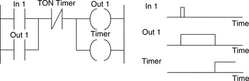
Figure 9.10 shows how a on-delay timer can be used to produce an off-delay timer. With such an arrangement, when there is a momentary input to In 1, both the output Out 1 and the timer are switched on. Because the input is latched by the Out 1 contacts, the output remains on. After the preset timer delay, the timer contacts, which are normally closed, open and switch off the output. Thus the output starts as on and remains on until the time delay has elapsed.
Some PLCs have built-in off-delay timers as well as on-delay timers and thus there is no need to use an on-delay timer to produce an off-delay timer. Figure 9.11a illustrates this concept for an Allen-Bradley PLC and Figure 9.11b for a Siemens PLC, illustrating the ladder diagram and the instruction list. Note that with Siemens, the timer is considered a delay item in a rung rather than a relay. In the rectangle symbol used for the timer, the 0 precedes the T and indicates that it is an off-delay timer.
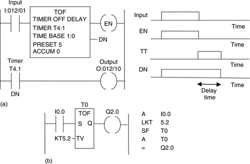
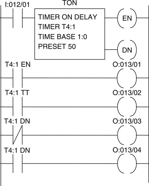
As an illustration of the use of an off-delay timer, consider the Allen-Bradley program shown in Figure 9.12. TOF is used to indicate that it is an off-delay rather than on-delay (TON) timer. The time base is set to 1:0, which is 1 s. The preset is 10, so the timer is preset to 10 s.
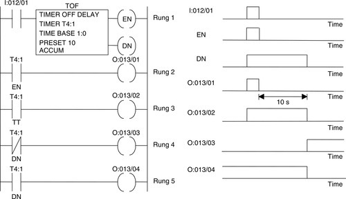
In the first rung, the output of the timer is taken from the EN (for enable) contacts. This means that there is no time delay between an input to I:012/01 and the EN output. As a result the EN contacts in rung 2 close immediately when there is an I:012/01 input. Thus there is an output from O:013/01 immediately when the input I:012/01 occurs. The TT (for timer timing) contacts in rung 3 are energized just while the timer is running. Because the timer is an off-delay timer, the timer is turned on for 10 s before turning off. Thus the TT contacts will close when the set time of 10 s is running. Hence output O:012/02 is switched on for this 10 s. The normally closed DN (for done) contacts open after 10 s, so output O:013/03 comes on after 10 s. The DN contacts that are normally open close after 10 s, so output O:013/04 goes off after 10 s.
9.4 Pulse Timers
Pulse timers are used to produce a fixed-duration output from some initiating input. Figure 9.13a shows a ladder diagram for a system that will give an output from Out 1 for a predetermined fixed length of time when there is an input to In 1, the timer being one involving a coil. There are two outputs for the input In 1. When there is an input to In 1, there is an output from Out 1 and the timer starts. When the predetermined time has elapsed, the timer contacts open. This switches off the output. Thus the output remains on for only the time specified by the timer.
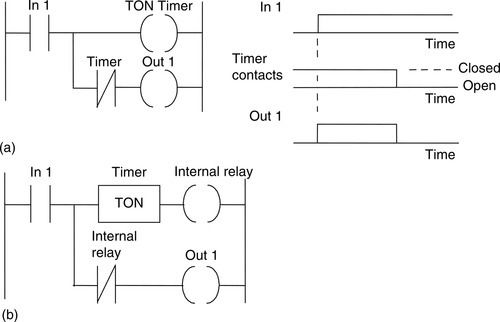
Figure 9.13b shows an equivalent ladder diagram to Figure 9.13a but employs a timer that produces a delay in the time taken for the signal to reach the output.
In Figure 9.13, the pulse timer has an output switched on by an input for a predetermined time, then switched off. Figure 9.14 shows another pulse timer that switches on an output for a predetermined time after the input ceases. This uses a timer and two internal relays. When there is an input to In 1, the internal relay IR 1 is energized. The timer does not start at this point because the normally closed In 1 contacts are open. The closing of the IR 1 contacts means that the internal relay IR 2 is energized. There is, however, no output from Out 1 at this stage because, for the bottom rung, we have In 1 contacts open. When the input to In 1 ceases, both the internal relays remain energized and the timer is started. After the set time, the timer contacts, which are normally closed, open and switch off IR 2. This in turn switches off IR 1. It also, in the bottom rung, switches off the output Out 1. Thus the output is off for the duration of the input, then is switched on for a predetermined length of time.

9.5 Retentive Timers
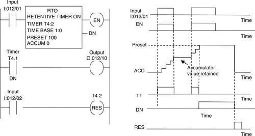
Some PLCs also have retentive timers. A retentive timer (RTO), such as that of Allen-Bradley (Figure 9.15), lets the timer start and stop without resetting the accumulated value. The retentive timer operates the same as a TON timer except that the accumulator is not reset when the timer enable goes to 0 and continues to increment whenever the enable bit goes to 1. When the accumulator bit reaches the preset value, the timer timing bit goes to 0 and the done bit to 1 and the accumulator bit remains in that state until a reset instruction is received.
9.6 Programming Examples
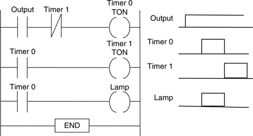
Consider a program (Figure 9.16) that could be used to flash a light on and off as long as there is some output occurring. Thus we might have both timer 0 and timer 1 set to 1 s. When the output occurs, timer 0 starts and switches on after 1 s. This closes the timer 0 contacts and starts timer 1. This switches on after 1 s and, in doing so, switches off timer 0. In so doing, it switches off itself. The lamp is on only when timer 0 is on, and so we have a program to flash the lamp on and off as long as there is an output.
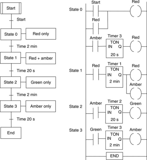
As an illustration of programming involving timers, consider the sequencing of traffic lights to give the sequence red only, red plus amber, green, and amber, then repeat. A simple system might just have the sequence triggered by time, with each of the possible states occurring in sequence for a fixed amount of time. Figure 9.17 shows the sequential function chart and a possible ladder program to give the sequence.
As another illustration of the use of a timer, consider Figure 9.18, which is a program to initially switch on motor 1 and its signal lamp 1, then after a time set by the timer to switch off motor 1 and signal lamp 1 and switch on motor 2 and signal lamp 2. When there is an input, the timer starts. Until the timer has timed out, the closed timer contacts remain closed and so motor 1 and lamp 1 are on; the open timer contacts remain open and so motor 2 and lamp 2 are off. When the timer has timed out, the closed timer contacts open and switch off motor 1 and lamp 1; the open timer contacts close and switch on motor 2 and lamp 2.
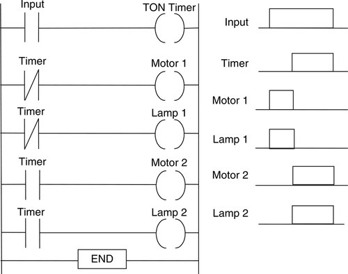
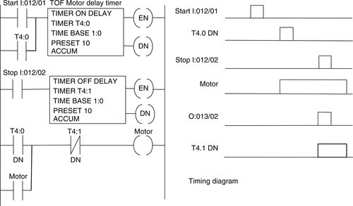
Figure 9.19 shows an example of where a TON timer and a TOF timer are both used to control a motor. The first rung starts with a start switch that is latched by the TON timer so that the input to it remains on, even when the start switch is no longer activated. After the delay time of the TON timer the motor is started. The motor is stopped by input to the Stop input, but the motor continues running for a time delay set by the TOF timer before finally stopping.
Summary
Timers are often considered to behave like relays with coils, which, when energized, result in the closing or opening of contacts after some preset time. However, some manufacturers treat a timer as a delay block, which, when inserted in a rung, delays signals in that rung from reaching the output. A number of forms of timers can be found with PLCs: on-delay TON, off-delay TOF, and pulse TP. With small PLCs there is likely to be just one form: the on-delay timer. With an on-delay timer, after the timer is switched on, the contacts close after a preset time. With an off-delay timer, contacts do not open until the elapse of the preset time after the timer is switched on. A retentive timer (RTO) lets the timer start and stop without resetting the accumulated time value.
Problems
Problems 1 through 21 have four answer options: A, B, C, or D. Choose the correct answer from the answer options. Problems 1 through 3 refer to Figure 9.20, which shows a ladder diagram with an on-delay timer, an input (In 1), and an output (Out 1).
1. Decide whether each of these statements is true (T) or false (F). When there is an input to In 1 in Figure 9.20:
(ii) There is an output from Out 1.
A. (i) T (ii) T
B. (i) T (ii) F
C. (i) F (ii) T
D. (i) F (ii) F
2. Decide whether each of these statements is true (T) or false (F). The timer in Figure 9.20 starts when:
(ii) The input ceases.
A. (i) T (ii) T
B. (i) T (ii) F
C. (i) F (ii) T
D. (i) F (ii) F
3. Decide whether each of these statements is true (T) or false (F). When there is an input to In 1 in Figure 9.20, the output is switched:
(i) On for the time for which the timer was preset.
(ii) Off for the time for which the timer was preset.
A. (i) T (ii) T
B. (i) T (ii) F
C. (i) F (ii) T
D. (i) F (ii) F
Problems 4 through 6 refer to Figure 9.21, which shows two alternative versions of a ladder diagram with two inputs (In 1 and In 2), two outputs (Out 1 and Out 2), and an on-delay timer.
4. Decide whether each of these statements is true (T) or false (F). When there is just an input to In 1 in Figure 9.21:
(ii) There is an output from Out 2.
A. (i) T (ii) T
B. (i) T (ii) F
C. (i) F (ii) T
D. (i) F (ii) F
5. Decide whether each of these statements is true (T) or false (F). When there is just an input to In 2 in Figure 9.21:
(ii) There is an output from Out 2.
A. (i) T (ii) T
B. (i) T (ii) F
C. (i) F (ii) T
D. (i) F (ii) F
6. Decide whether each of these statements is true (T) or false (F). When there is an input to In 1 and no input to In 2 in Figure 9.21, there is an output from Out 2 that:
(ii) Ceases after the timer preset time.
A. (i) T (ii) T
B. (i) T (ii) F
C. (i) F (ii) T
D. (i) F (ii) F
7. The program instruction list for a Mitsubishi PLC is LD X400, OUT T450, K 6, LD T450, OUT Y430. An input to X400 gives:
A. An output that is on for 6 s then off for 6 s.
B. An output that lasts for 6 s.
C. An output that starts after 6 s.
D. An output that is off for 6 s, then on for 6 s.
8. The program instruction list for a Telemecanique PLC is L I0,0, = T0, L T0, = O0,0. When there is an input to I0,0 there is:
A. An output that is on for 6 s then off for 6 s.
B. An output that lasts for 6 s.
C. An output that starts after 6 s.
D. An output that is off for 6 s, then on for 6 s.
Problems 9 and 10 refer to the program instruction list for a Mitsubishi PLC: LD X400, OR Y430, ANI T450, OUT Y430, LD X401, OR M100, AND Y430, OUT T450, K 10, OUT M100.
9. Decide whether each of these statements is true (T) or false (F). When there is a momentary input to X400:
(i) The output from Y430 starts.
(ii) The output from Y430 ceases after 10 s.
A. (i) T (ii) T
B. (i) T (ii) F
C. (i) F (ii) T
D. (i) F (ii) F
10. Decide whether each of these statements is true (T) or false (F). The output from Y430:
(i) Starts when there is a momentary input to X401.
(ii) Ceases 10 s after the input to X401.
A. (i) T (ii) T
B. (i) T (ii) F
C. (i) F (ii) T
D. (i) F (ii) F
Problems 11 and 12 refer to Figure 9.22, which shows a system with an input (In 1), an on-delay timer, and an output (Out 1). The timer is set for a time of 6 s. The graph shows how the signal to the input varies with time.
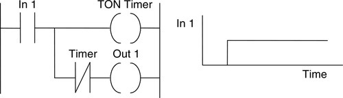
11. Decide whether each of these statements is true (T) or false (F). The output from Out 1 in Figure 9.22:
(i) Starts when the input starts.
(ii) Ceases 6 s after the start of the input.
A. (i) T (ii) T
B. (i) T (ii) F
C. (i) F (ii) T
D. (i) F (ii) F
12. Decide whether each of these statements is true (T) or false (F). The timer contacts in Figure 9.22:
(i) Remain closed for 6 s after the start of the input.
(ii) Open 6 s after the input starts.
A. (i) T (ii) T
B. (i) T (ii) F
C. (i) F (ii) T
D. (i) F (ii) F
Problems 13 through 15 refer to Figure 9.23, which shows a ladder program for a Toshiba PLC involving internal relays, denoted by the letter R, and a TON timer with a preset of 20 s.
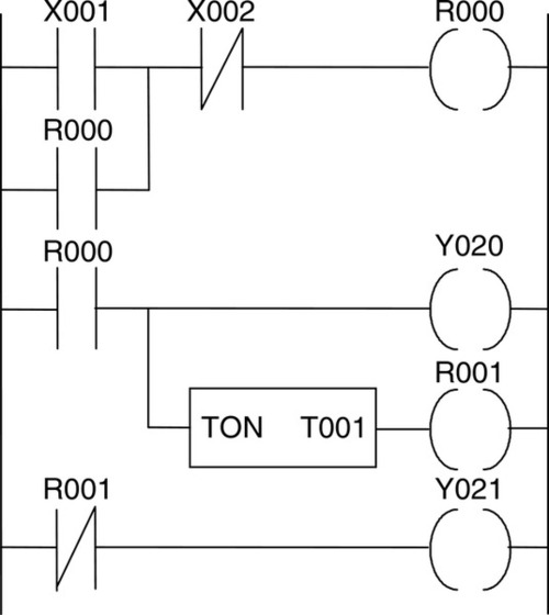
13. Decide whether each of these statements is true (T) or false (F). The internal relay R000 in Figure 9.23:
(i) Is used to latch the input X001.
(ii) Is used to start the timer T001.
A. (i) T (ii) T
B. (i) T (ii) F
C. (i) F (ii) T
D. (i) F (ii) F
14. Decide whether each of these statements is true (T) or false (F). With no input to X002 in Figure 9.23, the output Y020 is:
(i) Energized when there is an input to X001.
(ii) Ceases when there is no input to X001.
A. (i) T (ii) T
B. (i) T (ii) F
C. (i) F (ii) T
D. (i) F (ii) F
15. Decide whether each of these statements is true (T) or false (F). With no input to X002 in Figure 9.23:
(i) The output Y021 is switched on 20 s after the input X001.
(ii) The output Y020 is switched off 20 s after the input X001.
A. (i) T (ii) T
B. (i) T (ii) F
C. (i) F (ii) T
D. (i) F (ii) F
Problems 16 through 19 refer to Figure 9.24, which shows an Allen-Bradley program, and Figure 9.25, which shows a number of time charts for a particular signal input to I:012/01.

16. For the input shown in Figure 9.24, which is the output from O:013/01 in Figure 9.25?
17. For the input shown in Figure 9.24, which is the output from O:013/02 in Figure 9.25?
18. For the input shown in Figure 9.24, which is the output from O:013/03 in Figure 9.25?
19. For the input shown in Figure 9.24, which is the output from O:013/04 in Figure 9.25?
20. Decide whether each of these statements is true (T) or false (F). For the ladder program in Figure 9.26, with the timer set to 5 s, when there is an input to In 1:
(i) Out 1 is immediately activated.
(ii) Out 2 is activated after 5 s.
A. (i) T (ii) T
B. (i) T (ii) F
C. (i) F (ii) T
D. (i) F (ii) F
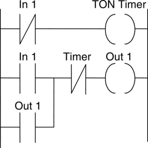
21. Decide whether each of these statements is true (T) or false (F). For the ladder program in Figure 9.27, with both timers set to 10 s, when there is an input to In 1:

(i) Out 1 is activated 20 s after the input occurs.
(ii) Out 1 is activated for a time of 20 s.
A. (i) T (ii) T
B. (i) T (ii) F
C. (i) F (ii) T
D. (i) F (ii) F
22. Devise ladder programs for systems that will carry out the following tasks:
(a) Switch on an output 5 s after receiving an input and keep it on for the duration of that input.
(b) Switch on an output for the duration of the input and then keep it on for a further 5 s.
(c) Switch on an output for 5 s after the start of an input signal.
(d) Start a machine if switch B is closed within 0.5 s of switch A being closed; otherwise the machine is not switched on.
Lookup Tasks
23. Look up the timers available for a particular range of PLCs.