
2 Formalized Approach for the Design of Real-Time Distributed Computer Systems
Ming Zhang, Bernard Zeigler and Xiaolin Hu
CONTENTS
2.2 Formal Approaches to the Design of Real-Time Distributed Computer Systems
2.3 DEVS as a Model-Based Design Formalization Tool
2.3.1 Model-Based System Design
2.3.3 DEVS as a Formalized Aid to System Design
2.4 DEVS-Based Formal Design Approaches for Real-Time Distributed Computing Systems
2.4.1 Design Aid for Real-Time Distributed VE
2.4.2 Design Aid and Verification for Real-Time Distributed Systems
2.4.3 DEVS Approach to the Design of Distributed Real-Time Cooperative Robotic Systems
2.1 Introduction
Real-time distributed computer systems combine virtual environment (VE)– based systems, real-time peer-to-peer (P2P)–based systems, quality-of-service (QoS)–aware distributed computer systems, and hybrid systems (the systems that incorporate both real-time and non-real-time behaviors). Efficient system design for such systems requires a sound framework that can facilitate effective design modeling and simulation (M&S) as well as support for flexible testing of design alternatives. Traditional approaches to system design do not use formal system specification languages or formalisms and are based on accumulated domain knowledge. Thus, system design, in many cases, is separated from system implementation, system testing, and system validation. With the rapid advances of distributed real-time computer systems, the complexity of such systems is increasingly challenging traditional nonformalized design approaches. Therefore, formal design methods have been widely used for system design in recent years, and such efforts have been verified by many researchers as suitable for large-scale and complex systems. Among different formal approaches, it is worth noting that model-based system design has proved to be one of the most efficient methods to address the key concerns in complex system design [1–4]. Indeed, the model-based design approach uses a formal language to describe system design models, and such design models are then simulated to predict the performance of the system in real-world scenarios. In particular, the model-based formal design using Discrete Event System Specification (DEVS) [5–7] differentiates it from most other approaches because of its use of a unique integrative framework that can address most of the issues faced in complex system design, and in particular, distributed real-time computer systems.
The DEVS formalism has become one of the most important components of M&S theory. It provides a conceptual framework and an associated computational approach for solving methodological problems in M&S communities. This computational approach is based on the mathematical theory of systems including the hierarchy of system specifications and specification morphisms. It manipulates a framework of elements to determine their logical relationships. As a formal system specification language, DEVS formalism and its associated M&S environment offers a very useful toolset for helping with complex system design and verification. Therefore, DEVS can be applied for precisely modeling the system components and their interactions and is therefore ideal for the design and evaluation of real-time dynamic software or embedded systems. Moreover, the recent advance of distributed DEVS opens up new potential for more efficient system design for real-time distributed systems including QoS-aware systems.
System design is a broad topic that has been addressed by many researchers [8,9]. Most recently, the advance of M&S techniques has greatly advanced system design by providing a more effective and reliable tool for designing large-scale and complex real-time distributed computer systems. In this chapter, we analyze and demonstrate how DEVS as a formalized approach can aid system design in a very flexible and efficient manner. We hold that DEVS, real-time DEVS (RT-DEVS), and distributed DEVS will continue to be among the most powerful tools for aiding complex system design, and in particular, real-time distributed computer systems including VE- and P2P-based systems.
The main contributions of this chapter are to
Demonstrate how DEVS can be used as a fundamental system design tool for distributed real-time computer systems.
Demonstrate how DEVS is used for design validation for complex real-time computer systems, such as distributed VEs, distributed real-time P2P systems, and distributed simulation systems.
Demonstrate how DEVS can be used as a fundamental technology for building a more advanced framework to support design of distributed real-time systems, such as cooperative robotic systems.
The rest of this chapter is organized as follows: Section 2.2 introduces existing formal approaches for design of real-time distributed computer systems. Section 2.3 focuses on a DEVS-based formal design approach including a brief review of model-based system design, as well as DEVS foundational theories and how it works as a sound tool to aid system design. Section 2.4 discusses DEVS-based formal design approaches for real-time distributed computing systems with several case studies. Finally, Section 2.5 concludes this chapter.
2.2 Formal Approaches to the Design of Real-Time Distributed Computer Systems
With the rapid advances of real-time distributed computer systems, the need for more efficient system design is called on to reduce the design cost and design life cycle. Moreover, the traditional design approaches cannot meet the requirement of today’s large-scale and complex real-time distributed computer systems because traditional nonformalized design approaches are error-prone, costly, and difficult to validate. Therefore, formalized system design approaches have been widely used in many areas for more efficient design of real-time distributed computer systems.
As a matter of fact, formalized system design has been proposed and clarified by some earlier researchers that can be traced back as far as the 1990s. For instance, Yau et al. [8] presented a research paper in 1990 that foresaw the best approaches for designing distributed computer systems. Their work classified the design approaches into three categories: dataflow oriented, communication oriented, and object oriented. A dataflow-oriented design approach basically uses structured analysis/ structured design [9,10] as the fundamental design method, which is based on the functional decomposition of the system. Therefore, the concurrency related issues are not directly handled in the design phase, which results in inefficient design for distributed real-time-based computer systems.
To overcome this problem, communication-oriented design methods are developed. However, because of the focus on concurrency naturally the functional aspect of the system is a secondary concern, which results in limitation of the communication-oriented approach to the design of communication intensive applications with simple data structures and computations within the system. Based on this classification, STATEMATE [11], various types of Petri nets [12, 13 and 14], SREM [15], and Raddle [16] are representatives of communication-oriented design approaches for distributed computer systems. Among these approaches, Petri net–based methods are well known in terms of behavior modeling and considered by many authors to be the best in this category. The key idea of a Petri net is to use “places,” “transition,” and a number of tokens to represent a system model. As such, the dynamic behavior of the system’s concurrent processes can be specified in terms of communication and synchronization among processes.
It is worth mentioning that some Petri net–based approaches have been aware of the limitation of the pure communication-oriented classic Petri net method, and, therefore, some “object” based architectural features were added to the Petri net concept. For example, a Net-based and Object-based Architectural Model (NOAM) for architectural modeling and prototyping of real-time distributed computer systems has been proposed [17]. NOAM supports progressive system decomposition and refinement to construct a hierarchically structured system architectural model that is modular, scalable, and executable. However, to understand and build a NOAM-based system model is a nontrivial task.
In contrast, an object-orient design approach can overcome the shortcomings of both dataflow-oriented and communication-oriented approaches. Most of today’s real-time distributed computer systems are built upon object-oriented concepts and programming languages; therefore, the object-oriented system design approach naturally fits the modern concept of system designs. Basically, object-oriented design can take full advantage of an object-oriented methodology to use a formal design specification language and tools in one unified domain. This approach can address both structural decomposition and communication in a distributed computer system. Indeed, many of today’s formal design tools are based on an object-oriented philosophy. However, there are major concerns with respect to synchronization and parallelism support as well as effective modeling tools (that can take full advantage of object-oriented methodology).
Timed automata as a formalism also shows its capability for modeling distributed real-time systems [18]. It employs timed automata for modeling a communication protocol with a main focus on verification of desired/undesired states in time- critical distributed applications. Other work [19] studied a formal design approach for middleware for distributed real-time embedded (DRE) systems. Considering the growing complexity of the middleware-based architecture, this work relied on timed automata to meet the need for detailed modeling of low-level middleware mechanisms. Meanwhile, evaluation of such models through model checking tools can greatly reduce the error at an earlier design phase. This work proposed a model-driven approach for the design of middleware-based DRE systems in which timed automata play the key role in formal system specification and model verification. Indeed, the use of timed automata has been a well-known key ingredient for designing real-time distributed computer systems. Application of timed automata for designing real-time distributed computer systems has been increasingly extended to new areas, including design of QoS-aware distributed real-time systems. As an example, recent work [20] used timed automata in a model-based approach for modeling and verification of both system behavior and QoS requirements in a distributed wireless network environment. In this research, timed automata were used for behavior modeling and model verification.
Unified Modeling Language (UML), as an object-oriented formal method, has also been widely adopted for designing computer systems including real-time distributed systems. The feasibility of using real-time UML as a formal design tool for distributed real-time computer systems has been discussed in Selic [21]. UML holds promise in the real-time domain, not only because it incorporates most of the basic modeling abstractions that the domain relies on but also because the flexibility of its stereotype mechanism allows these general abstractions to be specialized to the desired degree of accuracy. Other work by Gomaa and Menascé [22] investigated the component interaction patterns of a large-scale distributed system using UML as a formal specification language for performance modeling and system design. Both the synchronous and asynchronous communication mechanisms were studied by UML-based modeling. Moreover, a domain-specific formal semantic definition for a subset of the UML 2.0 component model was introduced, and an integrated sequence of design steps was then discussed [23]. Using UML for QoS-aware real-time distributed systems has also been investigated by many researchers. For instance, Bordbar et al. [24] discuss the design of a distributed system by using UML as the formal language for the specification. This work uses UML to model the computational viewpoint of the system with a focus on the description of QoS within that viewpoint. The resulting UML model can then serve as a template via which specific distributed system designs can be constructed.
Also known as an object-oriented formal system specification language, DEVS is playing an increasingly important role in aiding the design of complex real-time computer systems including real-time embedded systems, distributed real-time P2P systems, distributed VEs, and many more. The key difference between DEVS and aforementioned other object-oriented formal design approaches (such as those based on Petri nets and timed automata) lies in
The system design models can be directly simulated in one integrative environment that includes model specifications, simulators, and “experimental frames” (under which models are evaluated using appropriate simulators).
Because of their composability, the design model components are reusable through a model repository due to the separation of models from their simulators.
The model and simulator structure are natively hierarchical, which makes it easy to map them onto today’s complex computer systems.
To compare DEVS with aforementioned other well-known formal system design methods, we study how they are fundamentally different. For instance, in the approach using Petri nets, the real-time system design can be formalized and represented using a Petri net graph, through which the system behavior can be abstractly visualized and tested. The malfunctioning or undesired system behavior can thus be identified and analyzed. However, while complex hierarchical systems actually represent the majority of today’s real-time distributed computer systems, it is not straightforward to model such systems with Petri nets. How an individual system component affects the overall system design outcome is difficult to analyze. Moreover, how to obtain an optimal design from multiple design alternatives is also beyond the basic capability of a Petri net–based approach. In comparison, these issues are addressed fundamentally in a DEVS-based approach. Furthermore, another significant advantage of a DEVS-based approach is that the simulation models can be integrated with a real-time distributed computer system to form a virtual simulation environment. This environment then can combine both the system’s component models and real system components. This unique feature is not present in other formal methods, and it will be further demonstrated in Section 2.4.3. In the following sections, after the fundamental DEVS theories are introduced, we will demonstrate how DEVS can effectively aid system design in many different scenarios.
2.3 DEVS as a Model-Based Design Formalization Tool
As we have introduced, DEVS separates system models from their simulators, thus it natively supports a formal and model-based system design approach. In this section, we will discuss some background of DEVS as an effective model-based system design tool. To set the stage for the discussion of DEVS, we review model-based system design.
2.3.1 Model-Based System Design
With the rapid advance of today’s computer systems, a formalized system design process has been assuming an increasingly important role, in particular, for the design of distributed real-time computer systems. Traditionally, the design of such systems is independent from their implementation, test, and design validation. Thus, the overall design practice is time-consuming and error-prone. Model-based design is one of the modern approaches for complex system design. It is based on design models that attempt to capture the key system design parameters, and generally it requires the use of formal system specification languages, such as timed automata and DEVS. For instance, Schulz and Rozenblit [1] proposed a novel system codesign method using a formal specification language, such as DEVS, for aiding the design of embedded systems. Hu and Zeigler [2] proposed a model-based design framework for dynamic distributed real-time systems that introduces the concept of “model continuity,” which it leverages extensively. Indeed, embedded systems and distributed real-time systems are not the only areas in which a model-based formal design approach have been applied. The design of today’s VEs is also affected by the concept of a model-based approach, and the feasibility and effectiveness of using a model-based approach for designing VE systems have been investigated. For example, VR-WISE (a Virtual Reality modeling framework) has been employed as a tool for behavior specification and development [3]. It is actually a model-based design method, which makes the design of VEs more intuitive. One of the key advantages of VR-WISE is that it requires less virtual reality background and can be used by a broader audience [3]. Similarly, a simulation-based design methodology using composable models has been presented [4] that uses a tightly integrated design environment for the development of both the form and behavior of the system components.
Indeed, a model-based design approach opens a new direction toward solving complex distributed real-time computer systems. The application areas have been expanded to VEs, real-time P2P networks, and QoS-aware distributed systems, just to name a few. Compared to traditional approaches, model-based design involves not only building accurate design models but also simulating the design model in predefined experimental frames (EFs), through which design defects can be easily captured in the early design phases. Moreover, the optimal system design can be easily discovered by simulating models of design alternatives. Meanwhile, model validation becomes easy because of the use of a formal specification language.
2.3.2 DEVS and RT-DEVS
DEVS [5] is a mathematical formalism originally developed for specifying discrete event systems. DEVS is a well-known theoretical approach to M&S and has attracted many researchers for reliable and efficient system M&S. The key idea of DEVS is to use “atomic” models to express individual component’s behavior and to use “coupled” models to represent the interactions between the components in a system. The DEVS modeling framework fundamentally supports the reusability of individual models and also provides an efficient methodology for hierarchical model construction, which in turn can provide maximum flexibility for system M&S. As a pioneering formal M&S methodology, DEVS provides a concrete simulation theoretical foundation, which promotes fully object-oriented M&S techniques for solving today’s complex M&S problems.
As such, the standard and basic DEVS formalism consists of two formalisms, one for atomic models (AMs) and one for coupled models. The atomic DEVS is expressed as follows:
X: set of external input events,
S: set of sequential states,
Y: set of outputs,
δint: S → S: internal transition function,
δext: Q*Xb → S: external transition function, : Q X S
where
Q = {(s, e) | s ∈ S, 0 ≤ e ≤ ta(s)}
λ: S → Y b: output function,
ta: time advance function.
As a matter of fact, the AM is a building block for a more complex coupled model, which defines a new model constructed by connecting basic model components. Two major activities involved in defining a coupled model are specifying its component models and defining the couplings that create the desired communication networks. Therefore, a DEVS-coupled model is defined as follows:
where
X: set of external input events;
Y: a set of outputs;
D: a set of components names;
for each i in D,
Mi is a component model
Ii is the set of influences for i
for each j in Ii,
Zi,j is the i-to-j output translation function.
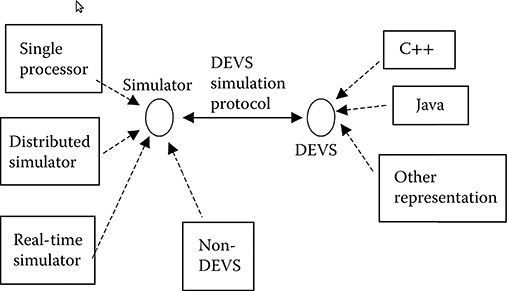
FIGURE 2.1 Discrete Event System Specification (DEVS) modeling and simulation framework. (From Zhang, M., Toward a Flexible and Reconfigurable Distributed Simulation: A New Approach to Distributed DEVS, PhD dissertation, Electrical and Computer Engineering Department, University of Arizona, Spring 2007. With permission.)
The DEVS M&S framework is very different from traditional module and function-based ones. It provides a very flexible and scalable M&S foundation by separating models and simulators. Figure 2.1 shows how DEVS model components interact with DEVS and non-DEVS simulators through the DEVS simulation protocol. We can also see that DEVS models interact with each other through DEVS simulators. The separation of models from simulators is a key aspect in DEVS, which is critical for scalable simulation and middleware-supported distributed simulation such as those using CORBA (Common Object Request Broker Architecture), HLA (high-level architecture), and MPI (Message Passing Interface).
The advantages of such a framework are obvious because model development is in fact not affected by underlying computational resources for executing the model. Therefore, models maintain their reusability and can be stored or retrieved from a model repository. The same model system can be executed in different ways using different DEVS simulation protocols. In such a setting, commonly used middleware technologies for parallel and distributed computing could be easily applied on separately developed DEVS models. Therefore, within the DEVS framework, model components can be easily migrated from single processor to multiprocessor and vice versa.
If we have a closer look at the DEVS-based modeling framework, we find that it is based on a hierarchical model construction technique as shown in Figure 2.2. For example, a coupled model is obtained by adding a coupling specification to a set of AMs. This coupled model can then be used as a component in a larger system with new components. A hierarchical coupled model can be constructed level by level by adding a set of model components (either atomic or coupled) as well as coupling information among these components. Consequently, a reusable model repository for developers is created. The DEVS-based modeling framework also supports a model component as a “black box,” where the internals of the model are hidden and only the behavior of it is exposed through its input/output ports.
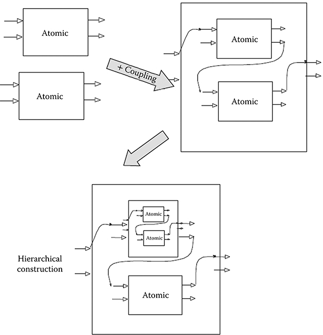
FIGURE 2.2 Coupled modules formed via coupling and their use as components. (From Zhang, M., Toward a Flexible and Reconfigurable Distributed Simulation: A New Approach to Distributed DEVS, PhD dissertation, Electrical and Computer Engineering Department, University of Arizona, Spring 2007. With permission.)
One interesting aspect of DEVS formalism is that a coupled DEVS model can be expressed as an equivalent basic model (or AM) and so DEVS models adhere to closure under coupling. Such an equivalent basic model derived from a coupled model can then be employed in a larger coupled model. Therefore, DEVS formalism provides a robust composition framework that supports closure under coupling and hierarchical construction.
RT-DEVS extends the aforementioned basic DEVS for real-time M&S applications. It differentiates from basic DEVS in that an activity set A and its associated mapping function ψ are added to the existing atomic DEVS to provide the real-time interaction capabilities for DEVS models in their environments. Thus, different model components in a real-time system can be encapsulated uniformly by this new formalism. Indeed, RT-DEVS formalism aims to solve the discrete event-based system problems because of the real-time requirement and is able to specify real-time distributed systems as DEVS models. The RT-DEVS formalism is defined by Hong and Kim [26], and an atomic RT-DEVS model can be expressed as follows:
X: set of external input events,
S: set of sequential states,
Y: set of outputs,
δint: S → S: internal transition function,
δext: Q*Xb → S: external transition function
where
Q = {(s, e) | s ∈ S, 0 ≤ e ≤ ta(s)}
Xb is a set of bags over elements in X,
λ: S → Yb: output function,
Yb is a set of bags over elements in Y,
ta: time advance function advances in real time)
A: set of activities with the constraints,
Ψ: S → A: an activity mapping function.
As a real-time extension of standard DEVS, RT-DEVS establishes the basis for using DEVS for system design when real-time concerns are key to a successful design. As a matter of fact, RT-DEVS has been adopted by many researchers as a fundamental method to investigate the hard-to-predict behavior of complex real-time distributed systems. Compared to other real-time formal specification languages, RT-DEVS extends all the advantages of standard DEVS, which makes the system design practices more efficient and reliable.
2.3.3 DEVS as a Formalized Aid to System Design
As discussed earlier, in recent years, many formal languages have been used to aid in system design, including UML [27], timed automata [28], Petri nets, [29] and statecharts [30]. However, to a large extent these formal languages have not been very suitable for the design of large-scale and complex systems because of the lack of effective model-driven engines (simulators), reusable model repositories, flexible model composition, etc.
DEVS [5] distinguished itself from these formalized system design approaches in that it can provide a more efficient system design modeling framework in which design alternatives can be easily constructed and simulated, as shown in Figure 2.3. Indeed, DEVS model-based design has been used by many researchers for solving complex system design problems. The key differences between DEVS and other formal approaches is that DEVS supports reusable hierarchical model development, and the DEVS design model can be simulated in one unified framework to quickly discover system design problems. In other words, DEVS can make it much easier to identify design problems, validate system design, and discover optimal system design.
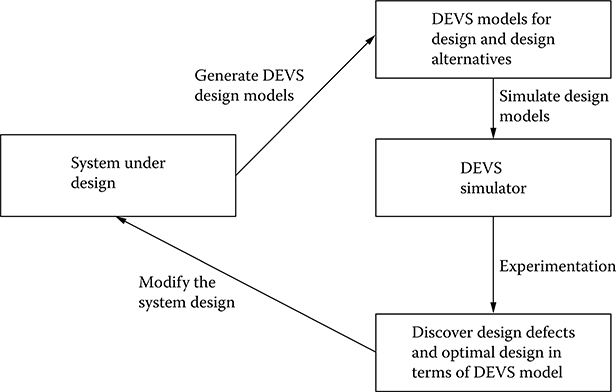
FIGURE 2.3 Discrete Event System Specification (DEVS) model-based approach for system design.
2.4 Devs-Based Formal Design Approaches for Real-Time Distributed Computing Systems
In this section, we will present how DEVS and RT-DEVS are used for aiding the design of real-time distributed computer systems. Several different types of distributed systems are involved, and we will see that the DEVS approach is not affected by particular system types. As such, it has great potential to be applied to any of today’s distributed real-time systems when other formal approaches are limited in their functionality.
2.4.1 Design Aid for Real-Time Distributed VE
Employing a VE is one of the leading computer techniques that has many application areas. Compared to other computer techniques, it can essentially provide a very attractive and user-friendly human–computer interaction platform by which the end users can play with the computer systems in a “like-real” fashion. Indeed, VE has been widely used in training, gaming, E-learning, and many other related areas [31–33]. It is worth mentioning that modern VE design is a complex process considering the many different components and their interactions in the system. Moreover, the design of modern VE systems involves many different novel computer techniques including object-oriented design, object-oriented programming languages, scripting languages, HTML- and XML-based web technology, and three-dimensional (3D) graphic rendering, just to name a few. In particular, the techniques for real-time 3D graphic rendering and distributing VE components in real time are playing important roles in today’s VE applications. Therefore, how to effectively apply the 3D technique into a distributed real-time computing environment brings a lot of challenges that are not faced in traditional VE approaches.
Indeed, designing an effective real-time distributed VE is a complex practice that involves using many different system design approaches. Compared to common software components, the interconnected and interacting virtual objects in a VE system must be precisely defined in terms of both visual effects and the behavior specifications. The real-time performance in a distributed computing environment, in fact, increases the complexity for specifying and implementing the visual object–based virtual world. This holds particularly true for traditional design techniques for VE, as they do not separate the design of visual objects and their behaviors, and moreover, they make little use of formalized methods as integrative design approaches. The problems brought about by nonformalized VE design are significant and include among many others: nonreusability of components, difficulty in behavior validation, and time-consuming implementation. Therefore, nonformalized VE design is not suitable for designing a large-scale and/or a complex VE system, in particular when it is distributed and will operate in real time. Instead, an integrative design platform to address the usability, performance, load balancing, etc. is required. Meanwhile, requirement specifications can also be an issue in the nonformalized VE design. Note that although substantial research is available on using formalized design practices for VE design [34–36], this work mainly focuses on the behavior design of the visual components/objects.
Traditionally, VE system design separates visual objects design from their behavior implementation. Visual objects design is directly manipulated by some visual modeling tools such as 3ds Max [37], AC3D [38], etc. However, the design of the behavior and implementation for a visual object is distinctly more difficult than the design of the visual object appearance because of the complexity of the behaviors of visual objects and their interactions. Furthermore, the real-time performance of the visual objects in a distributed environment is relatively difficult to predict in the design phase, which increases the necessity of a formalized design approach. Indeed, many formalized designs have been investigated by researchers to achieve a more efficient VE system design. These formalized design approaches use system specification languages to ease the design. For example, state-transition diagrams [34], FlowNet [35], HyNet [36], Tufts [39], Petri nets [29], and statecharts [30] have all been used for this purpose.
The drawbacks of these formal methods for the design of a complex VE system were introduced in Section 2.3.3 and have been gradually recognized in recent years. For example, FlowNet uses a graphical notation to specify the behavior of components, and when the specified VE system becomes large and complex, the resulting “FlowNet” is very difficult to understand and manage. Moreover, there exists no mapping of the specification created by these formalisms to the implemented visual objects, which makes design validation and optimization difficult to achieve. As we have discussed earlier, the DEVS-based M&S framework is a model-based system approach that is able to provide an integrated platform for aiding VE design. In the following paragraph, we discuss a practical example of using DEVS as an efficient tool for aiding the design of a web-based 3D VE system. We will see how a DEVS-based system design model can be easily realized in a simulation software environment, and how design validation and design optimization can be achieved through simulating a DEVS design model.
In recent research [32,33], a DEVS model-based approach for aiding the design of a 3D VE system, a virtual hospital, was discussed. This “virtual hospital” is a web-based distributed E-learning VE involving the design and implementation of many visual objects (such as “patient,” “x-ray scanner,” “touch sensor,” etc.) and system components (such as web components, database, user interface, etc.). The visual objects in the system are specified and designed using an X3D tool, while the interactions between these visual objects are defined and implemented using a scripting language. The behavior validation of the visual objects and the visual objects optimization are two key aspects in the design of this real-time distributed VE system. The authors used DEVS as the basic formalized tool to model the key visual objects and their interactions to validate their behavior specification and to find an optimal design. In fact, the behavior validation was conducted by running the DEVS model under a specified EF. This use of DEVS allows for the validation visual components’ behaviors quickly at an earlier stage of the system design. Thus, for example, some redundant or inefficient visual components can be removed in the final system implementation without losing any necessary system’s functionalities.
As shown in Figure 2.4, the key visual objects are realized in a DEVS integrated software framework, which is able to show models and their interaction using DEVS formalism. Here, the behavior of individual visual objects is defined using DEVS AM formalism, while the interaction of these individual visual object models are described by DEVS-coupled model specifications, or more specifically, the interactions are modeled by constructing messaging channels through individual input and output ports of the model.
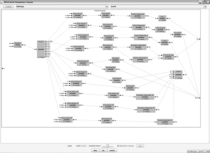
FIGURE 2.4 DEVSJAVA representation of a virtual hospital. (From Boukerche, A. et al., Concurrency & Computation: Practice & Experience, 21, 1422, 2009. With permission.)
As stated previously, each DEVS model component has strictly defined “states,” input and output “event” ports, as well as how the model responds to internal and external events. As an example, the “Touch Sensor” visual object is described as an atomic DEVS as follows [24]:
X={“In”}
Y={“Out”}
S={“passive”, “Touched”}
δint{“passive”, “Touched”} = {“passive”};
δext{“In”,{“passive”, 0 < e < infinite}} = {“Touched”};
λ{“Touched”} = {“Out”};
ta(“passive”) = infinite;
ta(“Touched”) = 0;
All other individual AMs are described similarly as the above “touch sensor” model. In terms of the behavior validation of each individual visual object, the representing DEVS model is tested under DEVSJAVA with different injected initial states. For instance, the “patient” visual object is modeled as an atomic DEVS “patient” model, and simulating this DEVS model can validate whether the behavior of the “patient” component defined in X3D is correct or not. Through testing and validating all these individual visual object DEVS models, any design error (in terms of visual objects’ behavior) can be discovered and eradicated easily. As a next step, the design inefficiency can also be identified by simulating a modeled subsystem of the virtual hospital. As an example, the authors examined the image animation of the “CT Scanner PC” component by simulating a corresponding DEVS design model (a coupled DEVS model in DEVS representation). As shown in Figures 2.5 and 2.6, a sequential operation steps of system components and their driving scripts (X3D Script) were presented, in which “X3D Scripts” take the data from “Scalar Interpolator” to generate the image file used in “PC Screen” (a visual component in the VE system being designed). Through mapping such operations to the DEVS model and then simulating them, it is discovered that the two “X3D Script” can be replaced by a new one as a better design. This is achieved by simulating the representing DEVS models to find a more efficient design alternative. Here, we can see that DEVS works smoothly as a guiding tool for design optimization. It is worth mentioning that DEVS models are easy to build, and simulation of DEVS models can help predict the performance of the designed VE system. Therefore, DEVS can not only be used as a design validation tool but also as a guiding tool for design optimization.

FIGURE 2.5 Image animation of CT scanner PC in the original X3D design. (From Boukerche, A. et al., Concurrency & Computation: Practice & Experience, 21, 1422, 2009. With permission.)
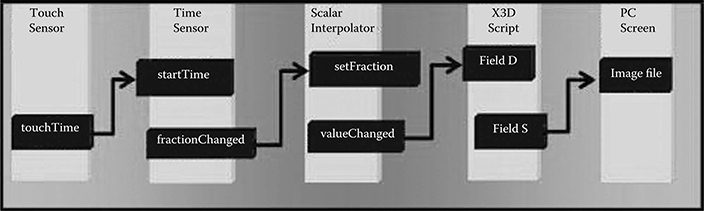
FIGURE 2.6 Image animation of CT scanner PC in the improved X3D design. (From Boukerche, A. et al., Concurrency & Computation: Practice & Experience, 21, 1422, 2009. With permission.)
2.4.2 Design Aid and Verification for Real-Time Distributed Systems
Indeed, VE-based systems can benefit from DEVS in terms of design validation and optimization. Real-time distributed computer systems, including real-time distributed simulation systems and QoS-aware distributed real-time computing systems, can also take advantage of using DEVS as the fundamental system design aiding tool. Indeed, the capability of precisely defining system components and their interaction makes DEVS a unique approach for effectively designing real-time distributed computer systems.
Real-time-based formal system specification languages have been widely studied, including UML-RT [27], timed automata [28], and others. For instance, UML-RT is quite suitable for the high-level formal description of a system (software, hardware, and the embedded system level), whereas timed automata can be used to precisely model the components of a system. As an extension of standard DEVS, RT-DEVS opens a wide area of specifying real-time computer systems, including distributed real-time systems and QoS-aware distributed systems. Compared to UML-RT and timed automata, RT-DEVS inherits the basic DEVS methodology and can also provide specification of real-time parameters, which can greatly help the design of a real-time distributed system in a unified platform (for example, the DEVSJAVA software platform).
As a well-known distributed simulation standard, HLA [40] has been widely adopted in the simulation community. Real-time interface (RTI) is the core in a HLA-based distributed simulation system. Therefore, the study of HLA-RTI has been attracting many researchers for a better RTI design. As a matter of fact, a real-time RTI (RT-RTI) system generally requires the participating simulation components to be deterministic, which exactly suits the DEVS formalism-based approach because DEVS and RT-DEVS are ideal for expressing the deterministic model behaviors to satisfy the requirements of designing a RT-RTI system. There exists very limited research that uses DEVS to aid a novel HLA-RTI design. In the following example, we will show how RT-DEVS is used to predict the key system design factors that can affect the overall performance of a RT-RTI system.
Other work [41] proposed a novel HLA-RTI design and used DEVS to validate their proposed real-time HLA/RTI [42] system design. RT-DEVS was used to specify the key RTI components, and the key performance parameters were captured by simulating the corresponding DEVS RTI models. As shown in Figure 2.7, the RTI design was realized as a DEVSJAVA simulation model, which represented the proposed new RTI design. The individual AMs were specified by RT-DEVS formalism. The overall real-time HLA/RTI system was modeled basically in three layers: task generation and task director (the “taskGen” and “director” models), HLA/RTI services (the six key HLA/RTI services are modeled as “DDM,” “DM,” “FM,” “OM,” “ObjM,” and “TM,” respectively), and the thread pools (five regular pools and one bigger pool). Thus, the dynamic behaviors of a designed HLA/RTI system can then be simulated by DEVSJAVA simulators.
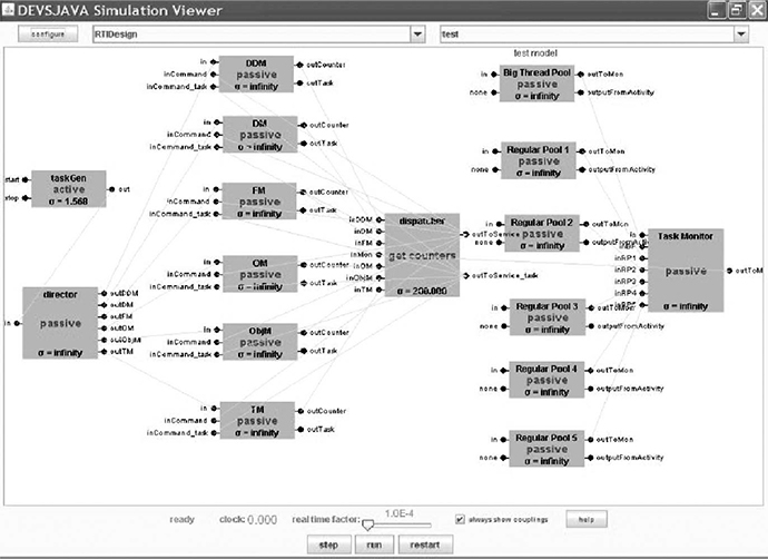
FIGURE 2.7 Real-time interface (RTI) design models in DEVSJAVA. (From Boukerche, A. et al., Simulation, 84, 231, 2008. With permission.)
For instance, the “service queue” AM is described with RT-DEVS as [41]
X={“input tasks”, “output counter”, “output task”} Y={“counter”, “task”}
S={“passive”, “outCounter”, “outTask”}
δint{“passive”, “outCounter”, “outTask”}={“passive”}
δext{“output counter”,{“passive”,0<e<infinite}} ={“outCounter”};
δext{“output task”,{“passive”, 0<e<infinite}}={“outTask”};
λ{“outCounter”}={“counter”}; λ{“outTask”}={“task”};
ta(“outCounter”)=0 ; ta(“outTask”)=0 ; ta(“passive”)=infinite
A={}
Ψ={}
and “Thread Pool” is described with RT-DEVS [41] as follows:
X={“input tasks”}
Y={“message”}
S={“passive”, “busy”}
δint{“passive”, “busy”}={“passive”}
δext{“input tasks”,{“passive”, 0<e<infinite}}={“busy”};
λ{“busy”}={“message”};
ta(“busy”)=constant value ; ta(“passive”)=infinite
A={“create and run task thread”}
Ψ{“busy”}={“create and run task thread”}.
As shown in the above RT-DEVS formalism, each model component (AM) has strictly defined “states,” input and output “events,” as well as how the model responds to internal and external events (transition functions). Different from standard DEVS, the real-time activity of the model is also defined using an activity set and an activity mapping function. Therefore, the overall system behaviors can be modeled and simulated in an integrated framework. Given that the key aspect of RT-RTI is its real-time performance (or, say, “task satisfactory rate”), the performance of a proposed novel RT-RTI core system must be evaluated and validated. In this research, the authors effectively used RT-DEVS as the design validation tool.
Figure 2.8 shows simulation on the DEVSJAVA platform of both the RT-DEVS models of the original RT-RTI and proposed novel RT-RTI designs. Indeed, the DEVSJAVA models in Figure 2.7 captured the key RT-RTI components and their real-time interactions so that the key performance parameters can be obtained. Consequently, the simulation results can be compared to the experimental results obtained from the executions in a physical RT-RTI environment. In particular, the key concern here is how dynamic thread pool management in the new RT-RTI design can benefit the performance of the overall RT-RTI system in terms of the tasks that are served to meet their deadlines. The experimental results, obtained from both the real RT-RTI execution and the DEVS model simulation, validated that the proposed novel RT-RTI design outperformed the original RTI system in terms of providing a better task serving rate in a real-time distributed simulation scenario. The DEVS simulation result, shown in Figure 2.8, provides a solid and consistent result that supports the proposed new RT-RTI design. In this example, we saw that the DEVS component-based design approach is able to discover, predict, and validate the key design concerns for a real-time distributed simulation system.
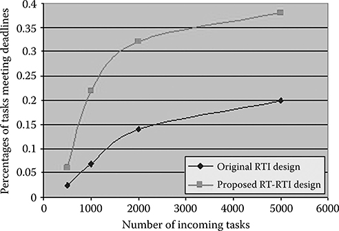
FIGURE 2.8 Discrete Event System Specification (DEVS) simulation result for real-time interface (RTI) design. (From Boukerche, A. et al., Simulation, 84, 231, 2008. With permission.)
In other work [43], RT-DEVS has been used to validate a design of a QoS-aware distributed real-time system. The design of such systems is a new area to explore with DEVS and the research created and implemented DEVS design models for both a tree-based (hierarchical) and a flat service management systems. These DEVS design models were then simulated in a real-time fashion, and the DEVS simulation results conform very well with the experimental results obtained in an actual P2P-based distributed cluster environment. Meanwhile, the “states” and “state transitions” of each component in the designed system were also validated by using a DEVS-based unit test method. It is worth mentioning that a QoS-aware system has many time-sensitive real-time parameters that must be considered during the design process, but how these parameters affect the overall real-time performance of the final designed system is generally very difficult to evaluate or predict. DEVS and RT-DEVS indeed provide a powerful system tool to facilitate the evaluation of such complex design processes in a quick and accurate way.
Another example demonstrates how RT-DEVS was used as a formalization technique toward aiding the algorithm design and validation of a P2P-based distributed system. In particular, a novel load-balancing algorithm in a P2P-based network was designed in which both dynamic QoS and service migration play key roles in terms of affecting the overall system performance [44]. The proposed load-balancing algorithm was based on a genetic algorithm [45], and the design of this algorithm was validated by a DEVS-based formal approach. The algorithm was modeled in a DEVSJAVA environment, which represents the key components and the behaviors of the algorithm in detail. Thus, the proposed algorithm can be simulated in terms of how it satisfies the user requirement in a dynamic distributed service-oriented system. The concept of DEVS “variable structure” was used to fulfill the requirement of modeling the variations of components in a dynamic system, which is actually one of the most important features for analyzing a service migration scheme in the proposed algorithm design.
The DEVSJAVA integrated environment provides the capability of visualizing the hierarchical system structure, which helps build the design models quickly. In terms of experimental evaluations, the proposed load-balancing algorithm (based on a genetic algorithm) was compared with two other systems: one only using task scheduling and one using no load-balancing algorithm. The proposed algorithm used a load-balancing manager that has dynamic QoS parameters implemented, and these parameters can be updated using a genetic algorithm. The three experimental distributed systems were also modeled in DEVSJAVA as shown in Figure 2.9, in which the computing services on hosted machines were modeled as “service nodes” and the multiple threads on one service were modeled as “node-i-thread-i” models. There is also a “task generation” model to generate tasks to the modeled system as well as a “MigrationManager” for task migrations. Two sets of experimental scenarios were created. In the first scenario, tasks were fed to the system using a fixed interval of 100 ms, whereas in the second scenario, the tasks were sent to the system using a different feeding rate so that the adaptability of the system could be evaluated. For both scenarios, experiments were conducted in both a practical P2P network and the DEVS model-based EF. As shown in Figures 2.10 and 2.11, the results obtained from DEVS models conforms well with the results captured in the practical P2P network. We can see that the DEVS simulations predicted higher task success rates when compared to the experiments in practice (conducted in real P2P-enabled computer networks) in both scenarios. This is because of the different experimental settings, and the key concern here is to validate the differences in the algorithms, not to exactly predict the performance of the algorithms in practice. Indeed, the experimental results imply that DEVS can provide accurate prediction of the performance of complex load-balancing algorithms for dynamic P2P-based distributed real-time systems. In the case where practical experiments are difficult to capture, DEVS and RT-DEVS can still provide effective prediction of the system performance using easy-to-build simulation-based models.
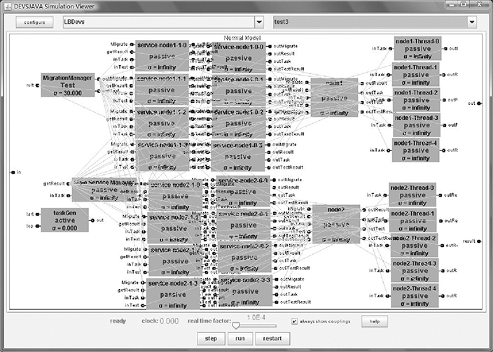
FIGURE 2.9 System design view in DEVSJAVA. (From Xie, H. et al., Concurrency & Computation: Practice & Experience. Vol. 22, P1223–1239, 2010. With permission.)

FIGURE 2.10 Simulation result obtained for the first scenario (a) in a real-world experiment; (b) in a Discrete Event System Specification (DEVS) simulation. (From Xie, H. et al., Concurrency & Computation: Practice & Experience. Vol. 22, P1223–1239, 2010. With permission.)
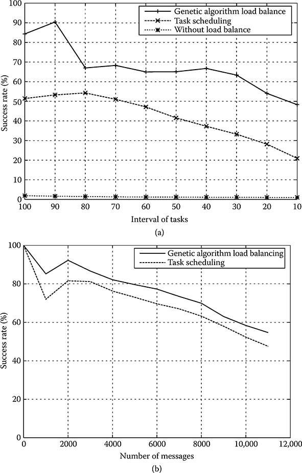
FIGURE 2.11 Simulation result obtained for the second scenario (a) in a real-world experiment; (b) in a Discrete Event System Specification (DEVS) simulation. (From Xie, H. et al., Concurrency & Computation: Practice & Experience. Vol. 22, P1223–1239, 2010. With permission.)
2.4.3 Devs Approach to the Design of Distributed Real-Time Cooperative Robotic Systems
In the previous discussion, we demonstrated some examples that use DEVS as a formal design validation tool to assist the design of complex real-time distributed systems. In this section, we will demonstrate how the DEVS formal approach can provide an integrative M&S environment to aid the design of distributed real-time cooperative robotic systems. In this subsection, we show how a physical robot can interact with a DEVS-based robot model in a simulation-based VE [46,47].
The DEVS approach presented in this section is based on an architecture proposed and implemented by one of the authors (Hu), which employs the following four steps for the design and testing of a cooperative robotic system [46]:
Centralized simulation to analyze the system under test within a model of the environment linked by abstract sensor/actuator interfaces on a single computer.
Distributed simulation, in which models are deployed to the real network that the system will be executed on and simulated by distributed real-time simulators.
Hardware-in-the-loop simulation, in which the environment model is simulated by a DEVS real-time simulator on one computer, whereas the control model under test is executed by a DEVS real-time execution engine on the real hardware.
Deployed execution, in which a real-time execution engine executes the control model that interacts with the physical environment through the earlier sensor/actuator interfaces that have been appropriately instantiated.
As the technology of robotic systems advances rapidly, systematic development methods and integrative development environments play increasingly important roles in handling the complexity of these systems. Compared to the conventional approach, the system architecture of Hu and Zeigler [46] supports robot-in-the-loop type of simulation, which can effectively overcome the difficulties of traditional approaches when the experimental environment confines the use of physical robots. One of the key ideas of this approach is to constitute an incremental study and measurement process for cooperative robotic systems combined with a simulation-based VE to support systematic analysis and measurement of large-scale cooperative robotic systems. Another highlight in this approach lies in the support of dynamic system reconfiguration in a real-time simulation of cooperative robotic systems. To enable this feature, “variable structure” DEVS [48] is used. This capability indeed makes dealing with the evolving cooperative robotic systems much easier. The concept of “experimental frame” is explored to form an integrative environment for studying the behaviors of large-scale cooperative robotic systems. In other words, the system architecture can be treated with a hybrid approach that allows real robots as well as virtual ones to be studied together in a simulation-based VE. This simulation-based VE was originally developed in the context of mobile robot applications; however, it can also be applied to other robotic applications such as object transportation and material handling. In the sequel, we demonstrate how physical robots can interact with the VE to form a cooperative real-time robotic system.
In general, robotic systems can be viewed as a particular form of real-time systems that monitor and respond to, or control, an external environment. This environment is connected to the computer system through sensors, actuators, and other input–output interfaces [6]. A robotic system from this point of view consists of sensors, actuators, and the decision-making unit. Thus, a cooperative robotic system is composed of a collection of robots that communicate with one another and interact with an environment. This view of robotic systems suggests a basic architecture for the simulation-based VE that we developed: an environment model and a collection of robot models, which include decision-making models, sensors, and actuators. The environment model represents the physical environment within which a robotic system will be operated. It forms a VE for the robots and may include virtual obstacles, virtual robots, or any other entities that are useful for simulation-based study. The robot model represents the control software that governs the decision making and communication of a robot. It also includes sensor and actuator interfaces to support interactions between the robot and its environment. In the approach by Hu, the “model continuity” methodology is used, which clearly separates the decision-making unit of a robot (which is modeled as a DEVS atomic or coupled model) from the sensors and actuators (which are modeled as DEVS abstractActivities). The decision-making model defines the control logic while the sensor/actuator abstractActivities represent the sensors or actuators, including their behaviors, interfaces, and properties of uncertainty and inaccuracy. DEVS-based model couplings are added between sensor/actuator abstract Activities and the environment model; therefore, messages can be passed between the decision-making model and the environment model through sensor/actuator abstractActivities.
It is worth noting that such separation between the decision-making model of a robot and its sensor/actuator interfaces can bring several advantages: First, it separates the decision making of a robot from hardware interaction. This makes it easier for the designer to focus on the decision-making model, which is the main design interest. Second, the existence of a sensor/actuator interface layer makes it possible for the decision-making model to interact with different types of sensors/actuators as long as the interface functions between them remain the same. Thus depending on different experimental and study objectives, a decision-making model can be equipped with different types of sensors and actuators. As a matter of fact, in this cooperative robotic system, models of sensors/actuators (modeled as abstractActivities, also referred to as virtual sensors/actuators hereafter) are developed to simulate the behavior of physical sensors/actuators. Meanwhile, physical sensor/actuator interfaces (implemented as RTActivities) are developed to drive the physical sensor/ actuators of a robot. A virtual sensor/actuator and its corresponding physical sensor/actuator interface share the same interface functions with the decision-making model. During simulation, a decision-making model uses virtual sensors/actuators to interact with a VE; during operation, the same decision-making model, which resides on a real robot, uses physical sensor/actuator interfaces to interact with a physical environment.
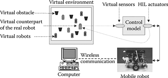
FIGURE 2.12 Robot-in-the-loop simulation. (From Hu, X., and Zeigler B. P., Integrated Computer-Aided Engineering, 12, 353, 2005. With permission.)
Figure 2.12 shows an example of the aforementioned cooperative robotic system, in which one physical mobile robot operates in a VE. In this example, the mobile robot uses its virtual sensors to get sensory input from the VE and uses its real motor interface to move the robot. As a result, the physical robot moves in a physical space based on the sensory input from a VE. Within this VE, the robot “sees” virtual obstacles that are simulated by computers and makes decisions based on those inputs. Meanwhile, virtual robots (robot models) can also be added into the environment so the physical robot can sense them and communicate/coordinate with them. This capability of robot-in-the-loop simulation brings simulation-based study one step closer to the physical world. Furthermore, for large-scale cooperative robotic systems that include hundreds of robots, it makes it possible to conduct system-wide tests and measurements without waiting for all physical robots to be available. In this latter case, the robots not yet physically available can be provided by the simulation-based VE.
Figure 2.13 illustrates how EFs, models/systems, and simulation methods can play together to carry out simulation-based measurement. This process includes three lines of development and integration: the “models/system” that will be tested and measured, the “EFs” that specify the measurement, and the “methods” that are employed to carry out the measurement. The process starts from the system specification that is formulated as DEVS-expressible formalisms. The system specification is further divided into two specifications: the design specification that guides the development of models/system and the measurement specification that guides the development of EFs. Three methods, corresponding to three stages of study, are used to carry out the measurement incrementally. These methods are conventional simulation, VE-based simulation, and real-time execution. Similarly, three types of EFs exist: EF for model-world study, EF for virtual-world study, and EF for physical-world study. Techniques are under development to derive EF development from the measurement specification in automated or semiautomated ways.
As a summary, the simulation-based VE supports a powerful hybrid approach that allows physical robots as well as virtual ones to be studied together. As the technology of robotic systems advances rapidly, systematic development methods and integrative development environments play an increasingly important role in handling the complexity of these systems. We can clearly see that DEVS is key to making it possible to build such a hybrid simulation framework, which can then aid the design of cooperation robotic systems more easily and effectively.
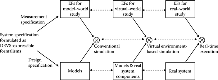
FIGURE 2.13 Experimental frames (EFs), models, and study methods. (From Hu, X., and Zeigler B. P., Integrated Computer-Aided Engineering, 12, 353, 2005. With permission.)
2.5 Summary
In this chapter, we demonstrated that DEVS and RT-DEVS can serve as an efficient system design framework for many of today’s complex real-time distributed systems. Compared to other formalized approaches, DEVS shows many advantages with its unique features, which include fast hierarchical model construction/reconstruction, model reusability, and ease of model validation. Furthermore, the flexible M&S tools and environments that DEVS enables can help in discovering optimal system design quickly as well as in validating existing designs.
Furthermore, we also expect that distributed DEVS can aid the design of distributed real-time systems in a more accurate and effective method. This is because distributed DEVS models can better represent physical systems. Thus, simulating distributed DEVS design models can provide a more accurate picture to identify the design defects and capture the key design parameters that must be effectively manipulated.
References
1. Schulz, S., J. W. Rozenblit, M. Mrva, and K. Buchenrieder. 1998. “Model-Based Codesign.” IEEE Computer 31 (8): 60–7.
2. Hu, X., and B. P. Zeigler. 2005. “Model Continuity in the Design of Dynamic Distributed Real-Time Systems.” IEEE Transactions on Systems, Man and Cybernetics—Part A: Systems and Humans 35 (6): 867–78.
3. Pellens, B., F. Kleinermann, O. D. Troyer, and W. Bille. 2006. “Model-Based Design of Virtual Environment Behavior.” In Proceedings of the 12th International Conference on Virtual Systems and Multimedia 2006, October 18–20, Xi’an, China, LNCS 4270, pp. 29–39.
4. Paredis, C. J. J., A. Diaz-Calderon, R. Sinha, and P. K. Khosla. 2001. “Composable Models for Simulation-Based Design.” Engineering with Computers 17: 112–28.
5. Zeigler, B. P., T. G. Kim, and H. Praehofer. 2000. Theory of Modeling and Simulation. 2nd ed. New York: Academic Press.
6. Shaw, S. C. 2001. Real-Time Systems and Software. New York: John Wiley & Sons.
7. Wainer, G. A., and P. J. Mosterman. 2010. Discrete-Event Modeling and Simulation: Theory and Applications. Boca Raton, FL: CRC Press.
8. Yau, Stephen S., Xiaoping, Jia, and Doo-Hwan, Bae. 1990. “Trends in Software Design for Distributed Computing Systems.” In Proceedings of Second IEEE Workshop on Future Trends of Distributed Computing Systems, Cairo, Egypt, September 30–October 2, 1990, pp. 154–60.
9. Sommerville, I. 1989. Software Engineering. 3rd ed. Wokingham, U.K.: Addison-Wesley Publishing Co.
10. Marco, D. 1918. Structured Analysis and System Specification. New York: Yourdon Press.
11. Harel, D., H. Lachover, A. Naamad, A. Pnueli, M. Politi, R. Sherman, A. Shtull-Trauring, and M. Trakhtenbrot. 1990. “STATEMATE: A Working Environment for the Development of Complex Reactive Systems.” IEEE Transactions on Software Engineering 16 (4): 406–14.
12. Yau, S. S., and M. U. Caglayan. 1983. “Distributed Software System Design Representation Using Modified Petri Nets.” IEEE Transactions on Software Engineering SE-9 (6): 733–45.
13. Ramamoorthy, C. V., Y. Yaw, and W. T. Tsai. 1988. “Synthesis Rules for Cyclic Interaction among Processes in Concurrent Systems.” In Proceedings of the 12th Annual International Computer Software & Applications Conference, Chicago, 1988, pp. 497–504.
14. Yau, S. S., and C.-R Chou. September 1988. “Control Flow Analysis of Distributed Computing System Software Using Structured Petri Net Model.” In Proceedings: Workshop on the Future Trends of Distributed Computing Systems in the 1990s, Hongkong, September 14–16, 1988, pp. 174–83.
15. Alford, M. 1985. “SREM at the Age of Eight: The Distributed Computing Design System.” IEEE Computer 18 (4): 36–45.
16. Evangelist, M., V. Y. Shen, I. R. Forman, and M. Graf. 1988. “Using Raddle to Design Distributed Systems.” In Proceedings of the 10th International Conference on Software Engineering, Singapore, April 11–15, 1988, pp. 102–11.
17. Yi Deng, Shengkai Lu, and Michael Evangelist. 1997. “A Formal Approach for Architectural Modeling and Prototyping of Distributed Real-Time Systems.” In Proceedings of the Thirtieth Annual Hawaii International Conference on System Sciences, Maui, Hawaii, January 7–10, 1997, pp. 481–90.
18. Jan, K., and H. Zdenek. “Verifying Real-Time Properties of Can Bus by Timed Automata.” http://dce.felk.cvut.cz/hanzalek/publications/Hanzalek04a.pdf., published 2004 online, accessed on July 2010.
19. Subramonian, V., C. Gill, C. Sanchez, and H. Sipma. “Composable Timed Automata Models for Real-Time Embedded Systems Middleware.” http://www.docin.com/p-87686529.html, published on 2005, accessed on July 2010.
20. Bordbar, B., R. Anane, and K. Okano. 2006 “A Timed Automata Approach to QoS Resolution.” International Journal of Simulation 7 (1): 46–54.
21. Selic, B. 1999. “Turning Clockwise: Using UML in the Real-Time Domain.” ACM Communications 42 (10): 46–54.
22. Gomaa, H., and D. A. Menascé. 2000. “Design and Performance Modeling of Component Interconnection Patterns for Distributed Software Architectures.” In Proceedings of the ACM WOSP 2000, Ottawa, ON, Canada, pp. 117–26.
23. Giese, H., M. Tichy, S. Burmester. W. Schafer, and S. Flake. “Towards the Compositional Verification of Real-Time UML Designs.” In Proceedings of the 9th European Software Engineering Conference, Helsinki, Finland, September 1–5, 2003, pp. 38–47.
24. Bordbar, B., J. Derrick, and G. Waters. 2002. “Using UML to Specify QoS Constraints in ODP.” Computer Networks 40: 279–304.
25. Zhang, M. Spring 2007. Toward a Flexible and Reconfigurable Distributed Simulation: A New Approach to Distributed DEVS. PhD dissertation, Electrical and Computer Engineering Department, University of Arizona.
26. Hong, J. S., and T. G. Kim. 1997. “Real-time Discrete Event System Specification Formalism for Seamless Real-Time Software Development.” Discrete Event Dynamic Systems: Theory and Applications 7: 355–75.
27. UML 2.0 Superstructure Specification. 2003 August. Available from OMG Adopted Specification.
28. Alur, R., and D. L. Dill. 1994. “A Theory of Timed Automata.” Theoretical Computer Science 126: 183–235.
29. van Bilion, W. R. 1988. “Extending Petri-Nets for Specifying Man-Machine Dialogue.” International Journal of Man-Machine Studies 28: 437–55.
30. Harel, D. 1987. “Statecharts: A Visual Formalism for Complex Systems.” Science of Computer Programming 8: 231–74.
31. Mosterman, P. J., J. O. Campbell, A. J. Brodersen, and J. R. Bourne. 1996. “Design and Implementation of an Electronics Laboratory Simulator.” IEEE Transactions on Education 39 (3): 309–13.
32. Hamidi, A., A. Boukerche, L. Ahmad, and M. Zhang. 2008. “Supporting Web-Based E-Learning Through Collaborative Virtual Environments for Radiotherapy Treatment: A Formal Design.” In Proceedings of the IEEE International Conference on Virtual Environments, Human-Computer Interfaces, and Measurement Systems, Istanbul, Turkey, July 14–16, pp. 51–6.
33. Boukerche, A., A. Hamidi, and M. Zhang. August 2009. “Design of a Virtual Environment Aided by a Model Based Formal Approach Using DEVS.” Concurrency & Computation: Practice & Experience 21 (11): 1422–36.
34. Hoare, C. A. R. 1978. “Communicating Sequential Processes.” Communications of the ACM 28 (8): 666–77.
35. Smith, S., and D. Duke. 1999. “Virtual Environments as Hybrid Systems.” In Proceedings of the Eurographics UK 17th Annual Conference, pp. 113–28.
36. Wieting, R. 1996. “Hybrid High-Level Nets.” In Proceedings of the 1996 Winter Simulation Conference, Coronado, CA, USA, December 8–11, 1996, pp. 848–55.
37. AutoDesk 3ds Max, http://usa.autodesk.com/adsk/servlet/index?siteID=123112&id=5659302.
38. AC3D, http://www.inivis.com/.
39. Jacob, R. J. K. 1996. “A Visual Language for Non-WIMP User Interfaces.” In Proceedings IEEE Symposium on Visual Languages, Boulder, Colorado, USA, September 3–6, 1996, pp. 231–38.
40. Dahmann, J. S., R. M. Fujimoto, and R. M. Weatherly. “The Department of Defense High Level Architecture.” In Proceedings of the 1997 Winter Simulation Conference, Atlanta, GA, USA, December 7–10, 1997.
41. Boukerche, A., M. Zhang, and A. Shadid. 2008. “DEVS Approach to Real Time RTI Design for Large-Scale Distributed Simulation Systems.” Simulation 84: 231.
42. IEEE Standard 1516-2000. 2000 September. “IEEE Standard for Modeling and Simulation (M&S) High Level Architecture (HLA)—Framework and Rules.”
43. Xie, H., A. Boukerche, M. Zhang, and B. P. Zeigler. 2008. “Design of a QoS-Aware Service Composition and Management System in Peer-to-Peer Network Aided by DEVS.” In Proceedings of IEEE International Symposium on Distributed Simulation and Real Time Application, Vancouver, BC, Canada, October 27–29, 2008.
44. Xie, H., A. Boukerche, and M. Zhang. 2010. “A Formalized Approach Formalization Designing a P2P-Based Dynamic Load Balancing Scheme.” Concurrency & Computation: Practice & Experience 22: 1223–39.
45. Melanie, M., 1996. An Introduction to Genetic Algorithms. Cambridge, MA: MIT Press.
46. Hu, X., and B. P. Zeigler. 2005. “A Simulation-Based Virtual Environment to Study Cooperative Robotic Systems.” Integrated Computer-Aided Engineering 12 (4): 353–67.
47. Hu, X. Fall 2003. “A Simulation-Based Software Development Methodology for Distributed Real-Time Systems.” PhD dissertation, Electrical and Computer Engineering Department, University of Arizona.
48. Hu, X., B. P. Zeigler, and S. Mittal. 2005. “Variable Structure in DEVS Component-Based Modeling and Simulation.” Simulation 81 (2): 91–102.