14
Introduction to LayOut
LayOut is a two-dimensional layout software. LayOut’s purpose is to allow you to take your 3D models from SketchUp and present them in 2D. This means giving you the ability to frame your 3D model on a page and add additional information via images or text. LayOut helps you present the ideas you have created with your SketchUp model to the rest of the world. 3D space is an amazing way to explore and plan, but when it comes time to convey information to others in a world where paper plans are the norm, a tool such as LayOut is the key to creating great-looking, easy-to-understand documents.
A copy of LayOut is installed alongside every single copy of SketchUp Pro. For this reason, it is always a little surprising to hear SketchUp users say that they have never used LayOut. This may make sense in some cases – that is, if a user is creating 3D assets for use in a video game, or is just using SketchUp to create geometry that is directly exported to a 3D printer. In most cases, however, professional workflows can require or be greatly enhanced by generating 2D documentation of models created in SketchUp, and with LayOut, generating those documents can be quick and easy, if you know what you are doing!
In this chapter, we will look at what LayOut is and the basics of how it works. Entire books have been written on creating LayOut workflows, so please see this as just a taste of what LayOut has to offer. The goal of this chapter is to give you an idea of what LayOut is and how it functions, rather than exhaustive training.
In this chapter, we will cover the following topics:
- Introducing LayOut
- Preparing a SketchUp model for LayOut
- Using LayOut with SketchUp models
- Adding detail to a LayOut document
- Generating output
Technical requirements
For this chapter, you will need LayOut and the Taking SketchUp Pro to the Next Level – Chapter 14.skp file, which is available at https://3dwarehouse.sketchup.com/model/414ae4a0-c3a8-41dd-aee6-c3ca154e7b86/Taking-SketchUp-Pro-to-the-Next-Level-Chapter-14.
Introducing LayOut
As mentioned in the introduction, many SketchUp users run SketchUp daily, have LayOut installed, and have at least seen the icon on their computer, but do not use it. Why is this? There are three reasons that I can think of:
- They need to use another program to generate their output. This makes sense for SketchUp designers that work in an office where output is standardized, and information passes back and forth throughout the firm and to other companies. Often, larger firms are required to have files generated from a specific program to satisfy the requirements of the companies they are working with or even the requirements of their government. In this case, it is understandable to have SketchUp as a piece of the grander workflow and create output in the software that is required.
- They use another program because it is the program they used before SketchUp. There are many SketchUp users that I have talked to who are not using LayOut because their firm has always created their drawings in AutoCAD, ArchiCAD, TurboCAD, and more. They will say that they already have templates created or they work with a drafter who prefers some other software. Frequently, these designers are already rocking the boat a little bit by choosing to create their models in SketchUp instead of another software, so I understand not wanting to attempt to push more change on their company.
- They don’t know or understand LayOut. This is the response I have heard the most. Users opened it once, clicked a few buttons but did not understand what they were looking at, and closed it back down. Sometimes, these users are generating output by taking screenshots of the SketchUp screen for output or using the export command to create a JPEG file, then taking that into some other software to generate output. They have created a clunky workflow where they pass inconsistent imagery around when they have a tool that will allow them to create high-quality, consistent output already installed on their computer. The only reason that they are not using LayOut is that they do not know that it is a better solution.
I will go on record right now and say that every SketchUp Pro user should develop at least a passing knowledge of LayOut. Regardless of which of the three of these groups you fall into, you can benefit from working with LayOut. It may be that you do not generate entire plan sets using LayOut, but the ability to position and organize your 3D models into good-looking 2D imagery can be helpful to almost any designer.
Despite its inclusion with SketchUp, many users resist diving in and learning how to use LayOut. I have seen some people with beautiful models asking how to best use the dimension tool and the export option in SketchUp to generate a “plan.” Others have complained that the dimension and text tools are too simple within SketchUp. The reason that it is not an easy process to generate a plan while inside SketchUp or why the text tools are so basic is that SketchUp was not intended to directly generate output. The text tools and dimension tools are there more as note-taking tools, giving you the ability to call something out for your reference. The image export options are there so you can get a quick snapshot of your model to share with a co-worker or show to a client to get quick feedback on a change you have made. When it comes to generating complete two-dimensional, detailed output that can be used to build or fabricate the subject of your model, you are looking for LayOut.
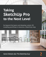
Take the following two figures as an example, both generated from the same model. Figure 14.1 shows the first one, which has been taken directly from SketchUp. Dimensions were added, and then the whole thing was exported as a 2D image:
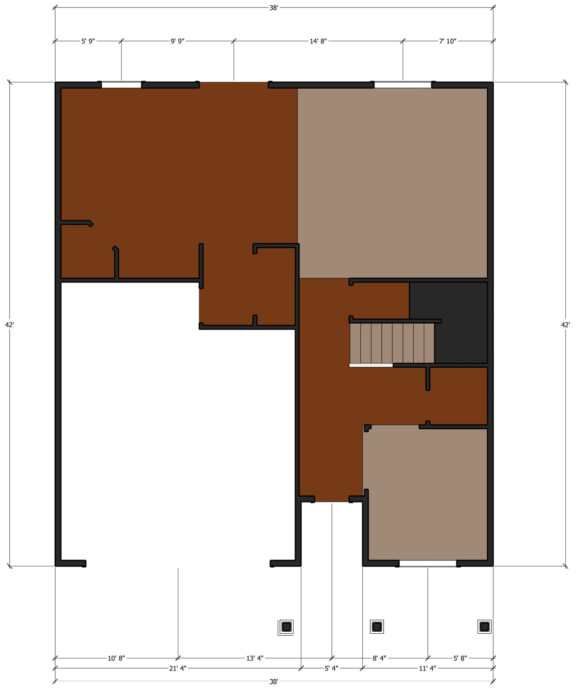
Figure 14.1 – Dimensioned floorplan exported directly from SketchUp
Not too bad, right? Well, consider that compared to a quick floorplan created in LayOut, like this:
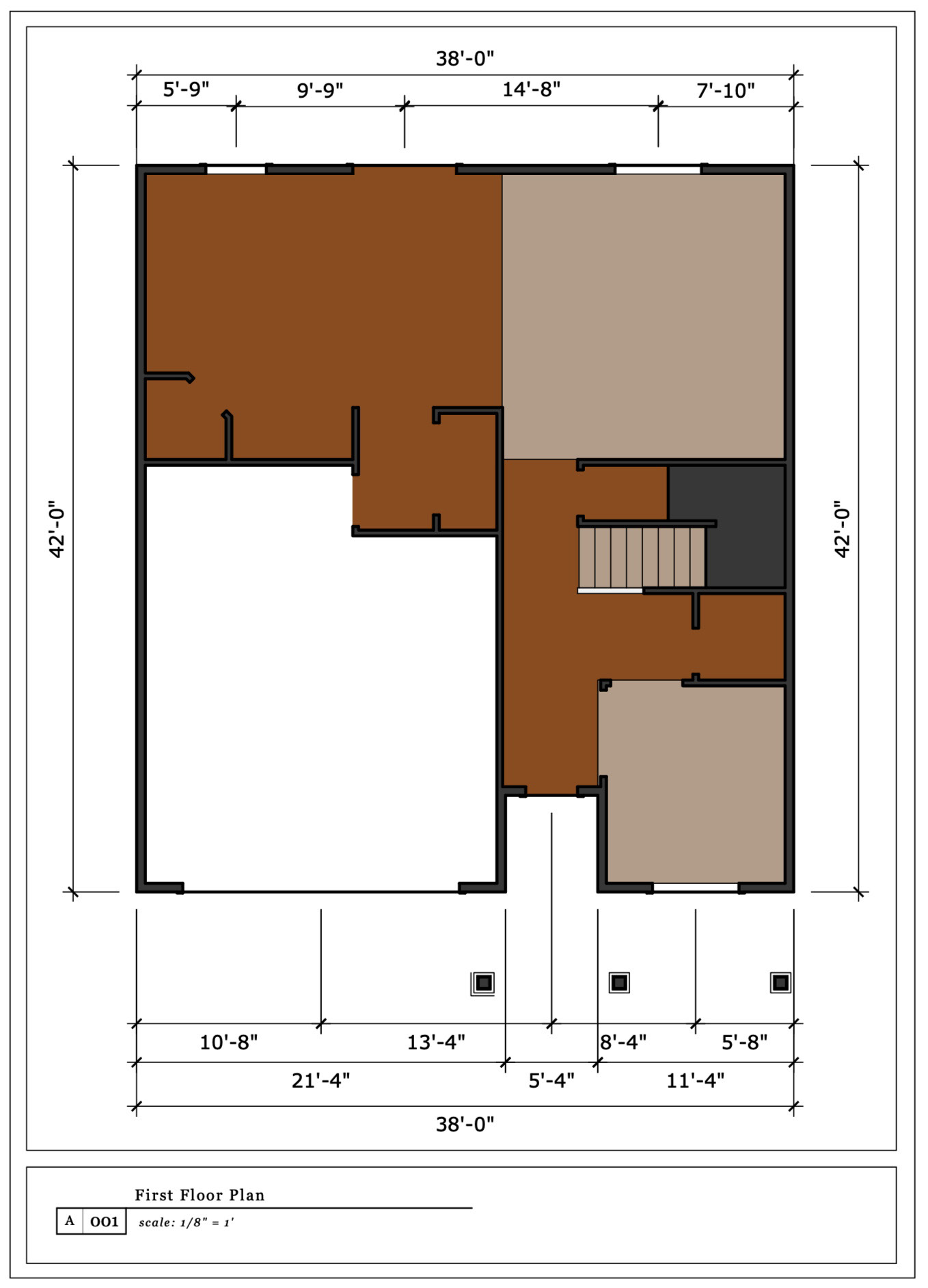
Figure 14.2 – Dimensioned floorplan created in LayOut
The biggest difference (besides the quality) was the amount of work that it took to generate. Once this model was imported into LayOut, the dimensions, text, and everything else were dropped onto the model image in half the time that it took to get the images drawn in the SketchUp model. This is not to say that the dimension tool in SketchUp is bad – it’s just that the tool in LayOut was created and intended for adding detail to 2D drawings. This means you can generate better-looking output with less work if you use LayOut.
None of this is to say that using LayOut is simple. One of the things that I hear most often is “It’s not like using SketchUp.” This is true. It is not like using SketchUp because it is not SketchUp. LayOut is its own software with its own workflows and tools. Some of them feel like something in SketchUp while others are different. If you can start learning LayOut by letting go of the idea that it is just like SketchUp, this will be a much easier process!
With that, let’s stop talking about using LayOut and start using it!
Preparing a SketchUp model for LayOut
While you could, in theory, start from scratch and just draw shapes right in LayOut, it was designed to work from an existing SketchUp model. While any SketchUp model can be inserted into a LayOut document, it will make generating documents much easier if you prepare your SketchUp model for LayOut. This does not have to be a complicated process and will look a little different for everyone, but we can run through a few things you can do in SketchUp that will save you time and energy once you get into LayOut.
Throughout this chapter, we will use the Taking SketchUp Pro to the Next Level – Chapter 14.skp SketchUp file to generate a LayOut document. Before we start looking at LayOut, let’s take a look at this file, which has been prepared to generate output, and see the sort of work you may want to do when getting a SketchUp file ready to generate documentation using LayOut.
Following Along
While you can simply read the descriptions, you may get more out of this section by opening the file in SketchUp and exploring the details we review here. If you do choose to do so, try not to make any changes, or save the file, as doing so may make it impossible to follow the step-by-step instructions later in this chapter.
Scenes
If there is one thing that you will want to set up in your SketchUp model to use in LayOut, it is scenes. As a general rule of thumb, using LayOut will be easiest if you have a scene created for every view you plan to use in LayOut. If you plan on creating a plan that includes four elevations and two floorplans, then you should have at least six scenes in your SketchUp model. If you plan to add two sections, then that is another two scenes. Let’s take a look at the scenes that exist in the Taking SketchUp Pro to the Next Level – Chapter 14.skp file:
Figure 14.3 – This file has 12 scenes
This model has 12 scenes saved. There is a Hero scene, which includes an isometric view of the entire model (likely for use on a cover page). It includes a scene for each of the four elevations and two sections. It also includes scenes for plan views of the first floor, second floor, and roof. Notice that there are two versions of the 1st and 2nd floorplans (clicking on them will show two different ways that you can present floorplans using SketchUp and LayOut).
While it is possible to create views of any SketchUp model from within LayOut, it is easiest to do so from pre-existing scenes. Using scenes will make it easier to make changes in SketchUp and update your LayOut documents with the changes. Creating scenes in SketchUp also allows you to take advantage of all the skills you have developed for moving through a model in 3D space. While you can use LayOut to move a model around to get to a specific view, it is much easier to do in SketchUp.
Tags
While tag visibility will be set by scenes (assuming you are using them), LayOut gives you access to tag visibility as well. You may not use this to turn entire floors on or off once you get into LayOut, but it is a nice option to have if certain things are getting in your way while you’re creating your drawings. Window casings, for example, may look good in your final drawings, but they may get in the way as you are adding dimensions. If they have their own tag, you can flip them off in LayOut, add your dimensions, then turn them back on before generating output.
Sections
Sections are a nice tool in SketchUp for working inside of a closed model. For LayOut, they are key to generating any drawing that is not outside your model. There are two scenes (Section A and Section B) that obviously use sections (click on them to see the view that is created). Sections are also used to generate floorplans. Click on any of the four floorplan scenes to see how horizontal section planes create a view down into the model.
As you explore the model, you will see that it has been cut using sections, but the section planes themselves are not visible! If you click Section Planes from the View menu, you can turn on all section planes and see where they lie. For each scene that was created using a section, one section plane was active, and the scene was saved with Section Planes turned off. This gives us a nice clean view inside the model without us having to see all of the section planes in the model.
Additionally, the sections in the floorplan scenes (all four of them) were used to generate a group that includes all of the geometry created from that section. The context menu’s Create Group from Slice command will create a group of line work composed of visible edges in the section. This may seem redundant since the section cut is already visible in the scene, but it does serve a purpose once you get into LayOut.
When adding dimensions in LayOut, you can pull dimensions from any of the normal snap points that you have access to in SketchUp. Since a section is only a representation of what it would look like if the geometry was split at the location of the slice and not an actual break in the geometry, there is no geometry there to connect dimensions to. Generating the slice of geometry will create edges throughout the section so that you can add dimensions to any points seen on the screen.
Creating a group of edges from a section is another example of a step that takes a few seconds in SketchUp but can make detailing in LayOut much easier.
Parallel Projection or Perspective
Something else that is generally saved in your scenes is the camera type. Most views that are used for generating printed output are created using the camera set to Parallel Projection. If you click through the scenes in this model, you will see that most of them are using this camera type. There are certain view types where you may want to use a perspective view. In this model, the Hero scene, as well as the alternative floorplans, include cameras set to Perspective. These different camera types will give you options for when you want to show depth in your drawings and when you want to show a flat isometric view of your model. While it is possible to change camera types from inside LayOut, it is easier to see and preview from SketchUp.
Styles
Styles, once again, will be saved in your scenes. From LayOut, you can change to any style saved in the SketchUp file. LayOut does not, however, have the ability to create new styles or edit existing styles. For this reason, it is important to save any styles you plan to use in your output into your model before you head off to LayOut.
These are the top points that are worth thinking about as you finish your SketchUp model and prepare to generate documentation. It is worth spending a little time just poking around the model in SketchUp to see how it is organized before proceeding to the next section, where we will import this file into LayOut.
Using LayOut with SketchUp models
The primary function of LayOut is to import SketchUp files and display them in 2D. I say primary because it is possible to use LayOut to do other things as well. There are drawing tools, so you could use LayOut to create some basic 2D drawings from scratch. There are also tools to add supplementary information (text, symbols, and dimensions) to complement the 2D versions of your models. You can also use LayOut to import other files (text, spreadsheets, or files exported from CAD) to your layouts. All these other capabilities, however, serve to add to that primary process of importing SketchUp files and readying them for output on a printed or digital page.
To that end, the first thing we will look at is how to import and place a SketchUp model into a LayOut document:
- Open LayOut.
Much like SketchUp, the first thing you will see when you start LayOut is a welcome window:
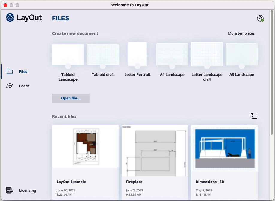
Figure 14.4 – LayOut welcome window, as seen on macOS
From this screen, you can choose a blank template to create a new file, open an existing file, or quickly open one of your most recently used files. For this walkthrough, we will create a brand-new document by choosing an existing template.
- Select More templates from the top-right corner of the welcome window.
This will display a page of existing LayOut templates for you to choose from. Notice that the top of the page has three tabs that you can click through:
- Paper will display templates that are standard paper sizes (from A3 up through tabloid size sheets) with or without a grid displayed on them.
- Storyboard includes a few templates of different aspect ratios that can be used for generating storyboards.
- Titleblock contains the most options, with templates of different page sizes that include title blocks of different kinds (Contemporary, Modern, Rounded, Simple, Simple Serif, and Traditional). These title blocks include a combination of text that can be manually edited and special text that will fill itself in when a SketchUp model is added to the page called auto-text. This text is controlled at a higher level, allowing you to change all instances of the auto-text with a single command.
Picking Favorites
Notice that, just like SketchUp templates, each LayOut template has a white circle below it. Clicking this circle will add a heart symbol, indicating that this is the default for new files. Once selected, that template will be used anytime you start a new LayOut document.
- In the Rounded section of Titleblock, choose the Tabloid Landscape template:
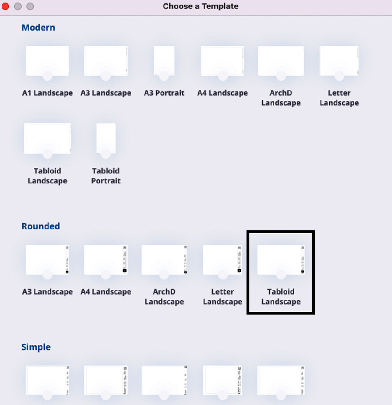
Figure 14.5 – The Tabloid Landscape sidebar is at the bottom of the template list
Exploring Templates
This example will explore LayOut using a specific template. The steps of this walkthrough will assume that you have selected the template listed in Step 3. However, I recommend that after you go through this walkthrough, you come back and explore the other stock templates. There are many options, and you may discover a template that you prefer over the one we are using in this example.
This will open LayOut, display the empty template, and give you access to the toolbars and panels that you will use to create your document (more on the UI elements in the Adding detail to a LayOut document section of this chapter).
Now that we have created a layout document, let’s create a good-looking cover page with our SketchUp model on it.
- In the Pages panel, click on 1: Cover Page.
This will make the cover page of the template active. Now, we just need to add our model to the page.
- Select Insert… from the File menu.
- Navigate to where you have saved the Taking SketchUp Pro to the Next Level – Chapter 14.skp file. Select the file and click on the Open button.
This will drop a SketchUp model viewport into the middle of the page:
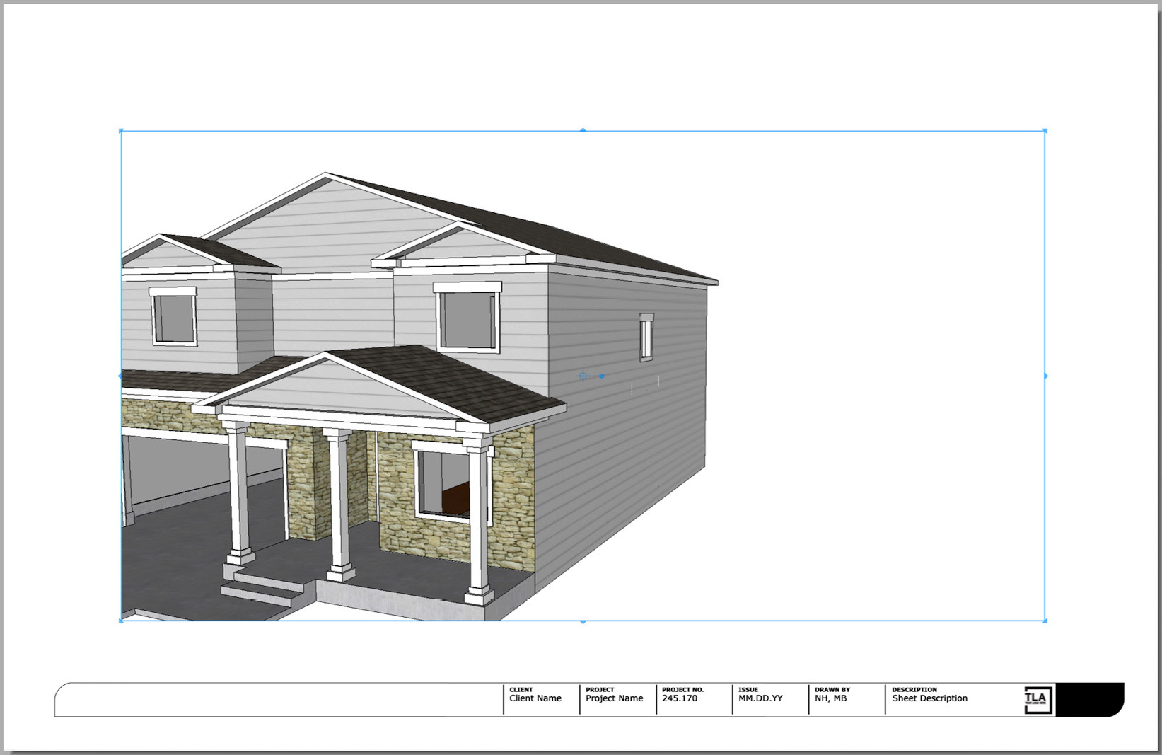
Figure 14.6 – Imported SketchUp model in LayOut
It is nice to see our model in LayOut, but it is currently not taking advantage of the size of the page. Let’s stretch out the viewport so that it fills the empty page in the middle of the title block.
LayOut Terminology
A document created in LayOut is called a LayOut file and has the .layout extension. A single LayOut file can have multiple pages (a page is a representation of a real-world page of paper that your world in LayOut will be printed on). Each page can have multiple viewports on them (a viewport is a container that allows you to view a SketchUp model). Each viewport can be connected to a different SketchUp model (or different views of the same model).
- Click on the Select arrow in the toolbar at the top of the LayOut window, then click on Model Viewport.
- Click and drag the top-left corner of the model window up to the top-left corner of the page.
- Click and drag the bottom-right corner of the model window down to the bottom-right corner of the page.
There is not a “perfect” place to drag the corners, but we want the image of the model to fill the page. In the end, you should have something that looks like this:
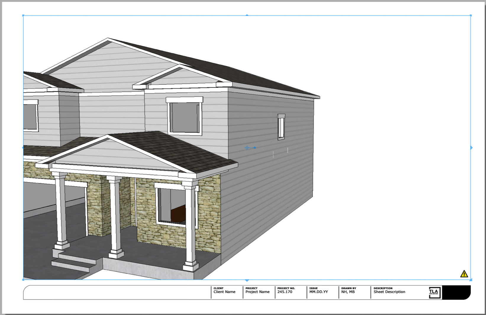
Figure 14.7 – Resized viewport makes for a bigger model
That Exclamation Point in a Yellow Triangle
Depending on your auto-render settings (more on this later in this section), you may get a little yellow triangle with an exclamation point in the bottom-right corner of your viewport as you edit your model. This icon shows up any time you do something that may make a change to how the content of a viewport should be shown. This is an indicator to you that the viewport needs to be re-rendered. If you are seeing this either before or after resizing the viewport, simply right-click on the viewport and choose Render Model.
The model is looking good, but it feels a little off center. Let’s drag the model (not the viewport) over to the right a little bit so that the end of the driveway is not spilling out of view. To do this, we need to edit the 3D view of the model in the viewport.
- Double-click on the model viewport.
You will notice that the appearance of the mode changes (the edges look different and the axes show up). When you are in the 3D view, you can navigate the same way you can in SketchUp; the view you end up on will be the one that LayOut will use in the viewport. This can be done using the scroll wheel of a three-button mouse (scroll to zoom in and out, click to orbit, Shift-click to pan) or you can right-click on the model and choose a specific tool from the Camera Tools menu (Orbit, Pan, Zoom, Zoom Window, Look Around, or Walk).
- Use your mouse or Camera Tools to change the view of the model.
While you can get to any view of the model using these commands, we need to get to a single view (for tutorial purposes). Let’s get back to the initial view we saw when we imported the model but zoom out so that the entire model fits in the viewport.
- Right-click on the model and choose Scenes from the context menu. Then, click Hero.
- Now, right-click on the model and choose Zoom Extents.
- To exit the 3D view of the model, click anywhere outside of the model viewport.
With that, your LayOut model should look like this:
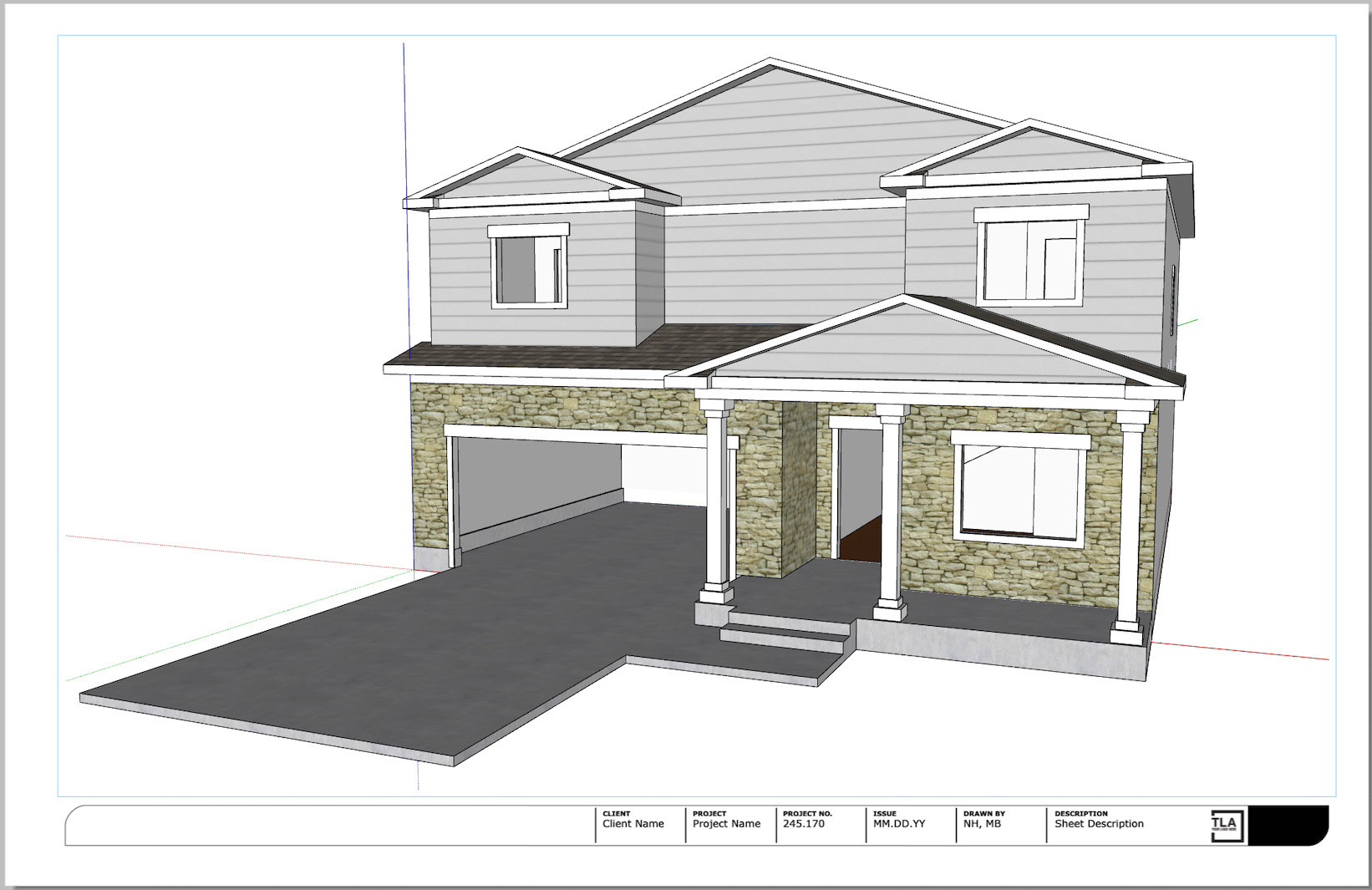
Figure 14.8 – Zoom Extents shows us the whole model
It should be noted that, while this first page contains only a single SketchUp model viewport, you can add multiple viewports linked to multiple SketchUp files if that is what you need. Whether you end up with a single SketchUp model viewport on a page or multiple, it is good to understand the link between these viewports and the files that populate them.
SketchUp file linking
Every SketchUp model viewport is linked to the .skp file that created it. If, at any point, you have changed the SketchUp file displayed in a viewport or if you want to change the file being referenced, you will need to modify the file references. These references can be found in the Document Setup window:
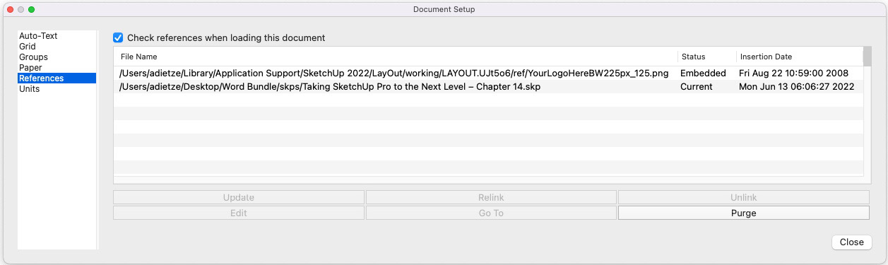
Figure 14.9 – The References tab of the Document Setup window
The Document Setup window can be accessed through the File menu (click File and then Document Setup…) and contains more than just references to external files. There are settings here for Auto-Text, Grid, Groups, Paper, and Units as well. While I will refer to some of these options later in this chapter, right now, I want to focus on how References works.
The References tab of the window will display a list of all external files (SketchUp files and other file formats) displayed in the current LayOut file. The list at the top will display a file path to the original file, as well as the status of the file and the date that it was inserted. The checkbox at the top of the window will cause LayOut to check referenced files every time this LayOut file is opened. If a file is ever missing or has changed from the version that was previously loaded, LayOut will color code the filename (blue for files that have been updated and red for missing files).
Here is a list of the six buttons below the list of references files:
- Update will become available if an updated file is selected from the list. Clicking this button will update the files in the model, displaying changes that have been made since the file was previously loaded.
- Relink will allow you to swap out the selected file for another. This is something that you may want to do if you have moved a linked file or want to change a file that is currently in your document for another.
- Unlink can be clicked to remove the active connection between a SketchUp model and its representation inside of LayOut. Normally, when you insert a SketchUp file into a LayOut document, LayOut maintains a connection between the files and allows you to keep the document up to date with the most recent information in the SketchUp files. If you choose to unlink the files, then the version of the SketchUp file in the LayOut document becomes detached from the original file and changes will not be shown.
- Edit will allow you to open the selected file in an external editor. For SketchUp files, this will launch SketchUp. For other files, LayOut will defer to your system’s default editor for the selected file type.
- Go To will display the file at its location in Explorer (on Windows) or Finder (on macOS).
- Purge will remove any files in the list that are not currently being used in your document. This can happen if you are editing a document and you remove a viewport. This will get rid of the content visually on the screen, but the link to the file will still exist. Clicking the Purge button will remove any reference to the file.
Understanding the status of linked files is key to updating your LayOut document while changes are being made to the SketchUp model. If a change is made to a SketchUp model, you will need to select it from the list and click the Update button. This will let LayOut know that you want to import and use the more recent version of the file. Once that is done, you will need to select the viewport from your document and then right-click to choose the Update Model Reference option. This will tell LayOut to update the displayed model to the newer version.
The process of maintaining SketchUp models is a key part of using LayOut. While we cannot look at every single aspect of file maintenance in this one chapter, we can look at a few more options when it comes to working with a SketchUp model in LayOut.
The SketchUp Model panel
The main portion of any LayOut document is the SketchUp model. SketchUp models are displayed in model viewports, which have a lot of options as to what information is displayed in the document. All of this information is controlled using the SketchUp Model panel:
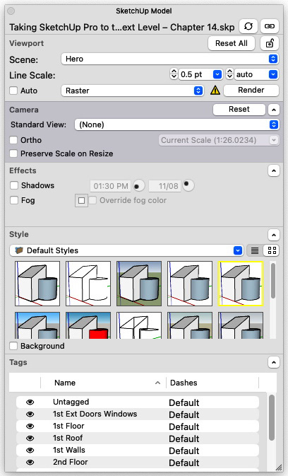
Figure 14.10 – The SketchUp Model panel
The SketchUp Model panel is a part of the Default Tray area on Windows and can be toggled on from the Window menu on macOS. This panel includes all of the information for a selected SketchUp model viewport. This panel is broken into five sections:
- The Viewport section is the top section of the panel and cannot be minimized. This section displays information such as the scene being displayed, line scaling information, and rendering options.
- The Camera section displays the current view. If the Ortho box is checked, it will allow you to set a scale for the viewport.
- The Effects section allows you to toggle the Shadow and Fog settings on and off.
- The Style section allows you to choose the style used to render the model in the viewport.
- The Tags section allows you to toggle specific tags on and off.
While it would be amazing to run through all of these sections in depth, for this overview, we are only going to take a look at the Viewport section and get an understanding of the rendering options. Make sure that the SketchUp Model panel is open and follow along:
- Use the Select tool to select the SketchUp model viewport.
The properties of the currently selected viewport will be displayed in the SketchUp Model panel.
- Make sure that the Auto box is not checked.
Auto will cause the viewport to redraw itself any time a change is made. In theory, this sounds like a good idea. However, since redrawing can be a time and resource-intensive process, it is better to manually tell LayOut when to re-render viewports. Any time I work with a SketchUp model viewport, I turn Auto off and manually render viewports by clicking the Render button to the right whenever I decide it is a good time to do so.
Name-Changing Render Button
The Render button will change its name based on the state of the selected viewport. If the selected viewport has changes that need to be re-rendered, then the button will be labeled Render. If the selected viewport is all up to date, then the button will read Rendered.
Notice that the rendering style (the bottom field in the Viewport section) is currently set to Raster. When set to Raster, edges can show up as kind of jagged or choppy:
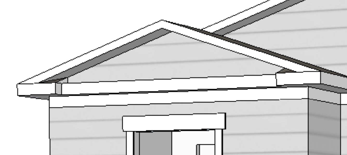
Figure 14.11 – Raster rendering style
This is because everything in a raster rendering is represented by a single pixel that is a single color. This may not be the prettiest way to display something like a drawing of your 3D model, but it is very quick to display.
Notice that the edges of the vector rendering are smooth, but we have lost the detail of the materials:
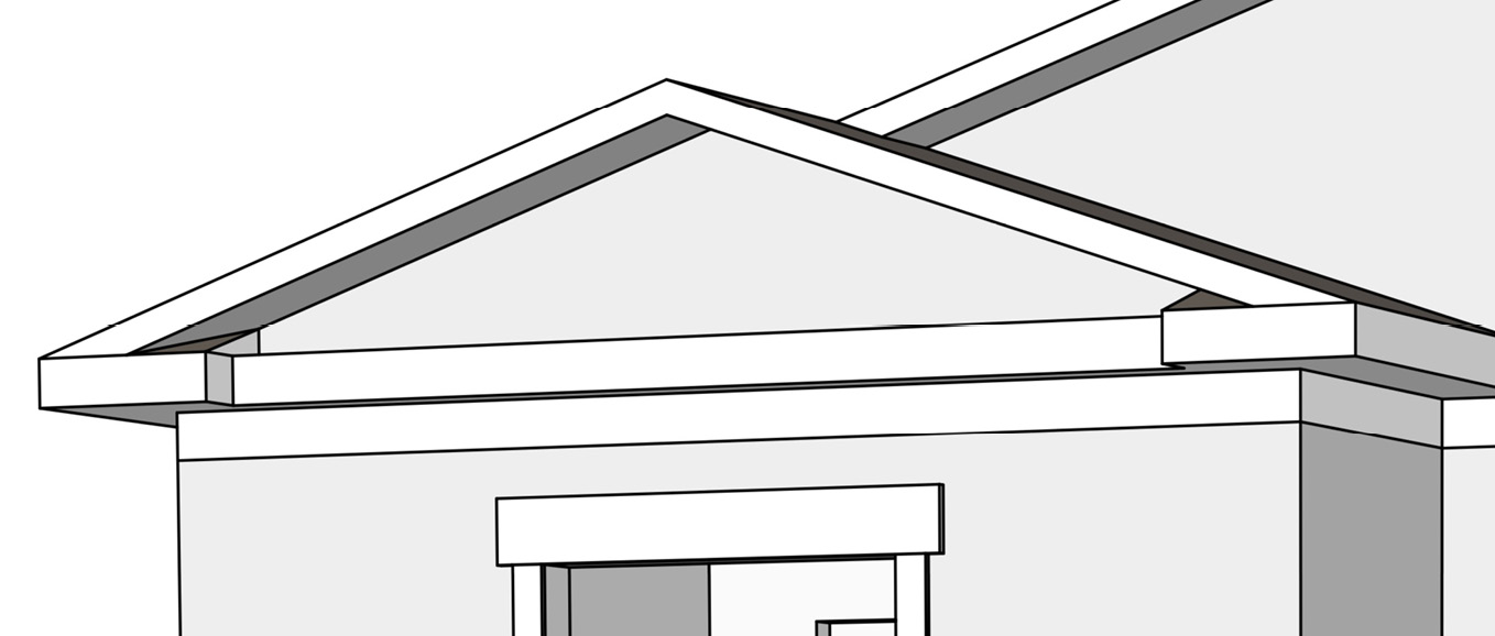
Figure 14.12 – Vector rendering style
Vector is a much better-looking rendering style for lines, but it does take longer to render. You also probably realized that we lost the materials from SketchUp and now everything is a single color. This rendering style can be a nice option if we want to skip over the details and just display line work.
This will display the lines from a Vector render over the top of the faces from the Raster render:
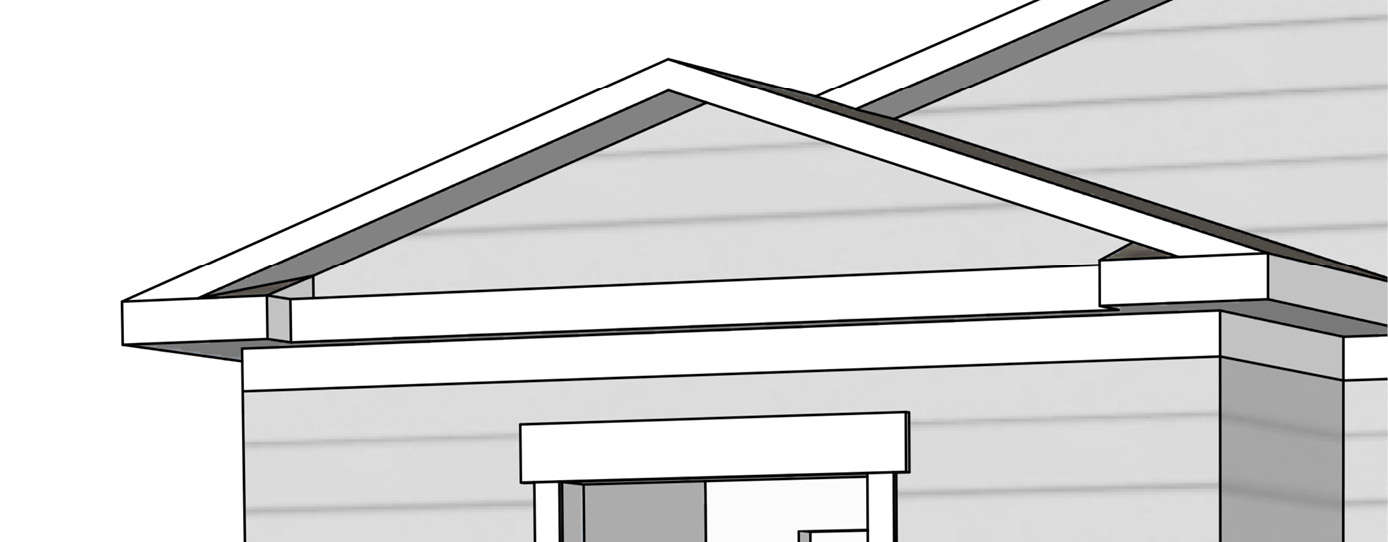
Figure 14.13 – Hybrid rendering style
This is the best of both worlds – smooth edges and detailed materials.
So, why give the option of rendering styles? Why not just always display Hybrid? By switching between styles, you have control over what is displayed in your output and how much time is spent rendering viewports! Many users will do all of their work while in the Raster rendering style because it is quicker. As you change what is displayed or update as changes are made, a Raster viewport will render quickly. Once the editing is done and it is time to generate output, the viewports can be switched to a Vector or Hybrid style. This can take a little bit of time to draw the edges but will make for a cleaner-looking output of the final documents.
It is important to know the different rendering options, but even more important is remembering to click that Render button as you make changes to your viewport.
Now that we have a basic understanding of how to work with a SketchUp model, let’s run through the rest of what LayOut has to offer.
Adding detail to a LayOut document
Placing a 2D version of a SketchUp model onto a page is great, but the real benefit of what can be done with LayOut is in the detailed information you can quickly add to your drawings. These details may be added using the tools and panels in LayOut and include things such as dimensions, text, labels, callouts, or even 2D entourage. The majority of this chapter will cover the process of adding additional information to our LayOut document. Before that, though, let’s take a quick run through the UI.
LayOut’s UI is different from SketchUp (which makes sense as it serves a different purpose) but similar enough that you should not have too hard a time navigating the commands. Just like SketchUp, there is a toolbar that houses all of the commands and can be customized (unlike SketchUp, there is only one toolbar, and it is locked into place). Just like SketchUp, there are a series of panels that display information and allow you to organize your model. These show up in a customizable tab bar on Windows and as floating, stackable panels on macOS.
While we will not have the time in this chapter to run through examples of every command in LayOut, we can provide an overview so that you have an idea of where commands are located and what each one does.
Toolbar
As mentioned previously, there is a single toolbar in LayOut and it is at the top of the LayOut window, as shown here:
Figure 14.14 – The default toolbar as seen on macOS
This toolbar can be customized the same way that toolbars are customized in SketchUp (through the View menu) and contains commands that can also be accessed through the menus.
As we explore LayOut’s UI further, you will see that the commands differ quite a bit from what SketchUp offers. The thing to remember with LayOut is that the commands are intended to allow you to position imagery and data on a page and add annotations. If you keep LayOut’s core purpose in mind as you learn more about it, then the commands and UI will make a lot of sense.
Menus
The menus in LayOut house the commands in LayOut. Some of the menus are intuitive as they parallel SketchUp’s menus, but a few might be confusing as they house commands that do not have an equivalent. Let’s look at what resides in each menu:
- File: This menu contains standard file commands for opening, saving, and closing documents, as well as commands for saving templates and scrapbooks (collections of 2D drawing elements that can be dropped onto a document). Most importantly, the command to insert a file (as we did in the example in the Using LayOut with SketchUp models section) and Document Setup… (which brings up the settings for your document) can be found in the File menu.
- Edit: Standard edit commands are found here (Undo, Redo, Cut, Copy, and Paste), as well as options to duplicate, change layers of selected items, group, and explode. The Edit menu is also home to masking commands.
- View: Just like in SketchUp, this menu contains commands that allow you to look around your document. All the zooming commands are here, along with Pan. The View menu also contains commands for toggling the UI on and off, as well as a command that shows a grid on your document.
- Text: This menu is pretty self-explanatory. All of the commands that allow you to change how on-screen text looks are housed here. Additionally, the command to create auto-text sits in this menu.
- Arrange: Unlike SketchUp, which has you placing items in 3D, LayOut is focused on 2D layouts, which means that items will lay on top of one another. Commands to control the order of these items are found in this menu. Commands to align or space selected items can also be found in this menu.
- Tools: All of the drawing and annotation commands are housed in the tools menu, as well as the commands that allow you to edit or manipulate them. If you want to add something to your document that is not connected to an external file, it is added with commands from the text file.
- Pages: This menu contains all of the commands that are used to organize and navigate the pages that make up a LayOut document.
- Window: All of the panels used in LayOut can be toggled on or off through this menu. The Colors and Fonts windows can also be accessed here.
- Help: Standard help commands and information are available through this command.
Preferences
The Preferences window contains all of the LayOut settings that are not saved with the document. This is a very important window and is one of the few commands that changes based on your operating system. If you are on Windows, it is in the Edit menu, while macOS users will find it in the LayOut menu.
While many of the commands you will use are found in the menus (and in the toolbar), the most commonly used bits of the UI are its panels. These panels not only contain information about the elements that make up a LayOut document but also allow you to manipulate and modify the elements.
Panels
Very similar to SketchUp, LayOut has a stack of panels that display information about selected items and allow you to set item properties:
- Shape Style: This panel allows you to set the appearance of any items in LayOut. This includes any lines or shapes drawn with the tools. You can even use this panel to add borders to SketchUp model windows!
- Scaled Drawing: This panel allows you to create a new viewport in which you can draw at a specified scale. Normal items that are drawn in LayOut (using the tools) are created at a one-to-one scale. When you create a Scaled Drawing viewport, you can specify the scale of that viewport and draw it using real-life dimensions.
- Pattern Fill: If you create geometry using the tools and want to fill them with something other than a solid color (which can be achieved using the Shape Style panel), the Pattern Fill panel will allow you to pick a pre-made pattern to use as a fill instead.
- SketchUp Model: This panel allows you to set the properties and appearance of a selected SketchUp model viewport.
- Dimension Style: This panel gives you all the attributes of selected dimensions.
- Pages: This panel allows you to create, reorder, remove, and navigate the pages that make up your LayOut document.
- Layers: Layers are groups of items (anything from model viewports to dimensions to single lines drawn using the Line tool) that are placed in the order that they should be drawn. The Layers panel allows you to create, reorder, and remove layers in the document.
- Scrapbooks: Scrapbooks allow you to create reusable 2D drawing elements. The Scrapbooks panel allows you to navigate a library of pre-drawn elements that you can drag and drop onto any document.
- Instructor: This panel gives you information about the current tool. This is a great panel to have open as you learn LayOut as it actively changes the information displayed to what you need based on the activity you are currently performing.
This was a quick overview of the tools and panels. While it is great to know what commands are and where they are, learning how to use them is even better. Let’s use the UI we just learned about to add another page to our document and add some annotations.
Using LayOut’s tools and panels
Now, we will spend some time learning how to use the tools and panels to do some basic editing of our LayOut document. First, let’s take a look at something simple: editing text.
Editing the project title
Let’s start by changing the project title in the title block of our document:
- Using the Select tool, double-click on Project Name on the right-hand side of the title block.
- Notice that as soon as you double-click, the words change from Project Name to <ProjectName>. Any time you see words or numbers inside angle brackets, it is an indicator that auto-text is being used.
- Click the File menu and then choose Document Setup…. Click on the Auto-Text option on the left.
This will list all of the auto-text options in the document. Notice the <ProjectName> text that we have in the title block. To the right of the auto-text is the value that will be displayed. Currently, the text being displayed is PROJECT NAME.
- Select the <ProjectName> auto-text from the list.
Notice that the information about the auto-text populates the bottom portion of the window. From here, you can replace the existing text.
- Replace the existing text with Example House, then click the Close button.
When we return to the LayOut document, the <ProjectName> auto-text will still be highlighted.
- Click outside of the selected text to close it.
Notice that the text that replaces the auto-text is Example House. This is great because we can use this auto-text in place of using a final project name. Then, as the project matures, if the owner names change, or the address changes, we can update the project name in one place and all instances will be updated.
Next, let’s let see what it takes to add more pages to our document.
Adding pages to a LayOut document
To add more pages, we will start by copying the SketchUp model viewport from the cover page onto our first inside page:
- Select the SketchUp model viewport and then click the Edit menu and choose Copy.
- In the Pages panel, click on 2: Inside Page.
- Click the Edit menu and choose Paste.
This will place an exact copy of the model from the cover page on our first inside page. This is a good start but not what we want. First off, we will have to resize the viewport just slightly.
- Use the Select tool to drag the corners of the viewport so that they fill the page.
Now, let’s change the view of the model on this page to a plan view of the first floor.
Changing the model viewport
We have a new page with a new model viewport, but we need to change the view of the model that we are seeing. Follow these steps:
- Select the SketchUp model viewport.
- In the SketchUp Model panel, change Scene to 1st Floorplan (traditional), then click the Render button.
As shown in the following screenshot, this does not look right:
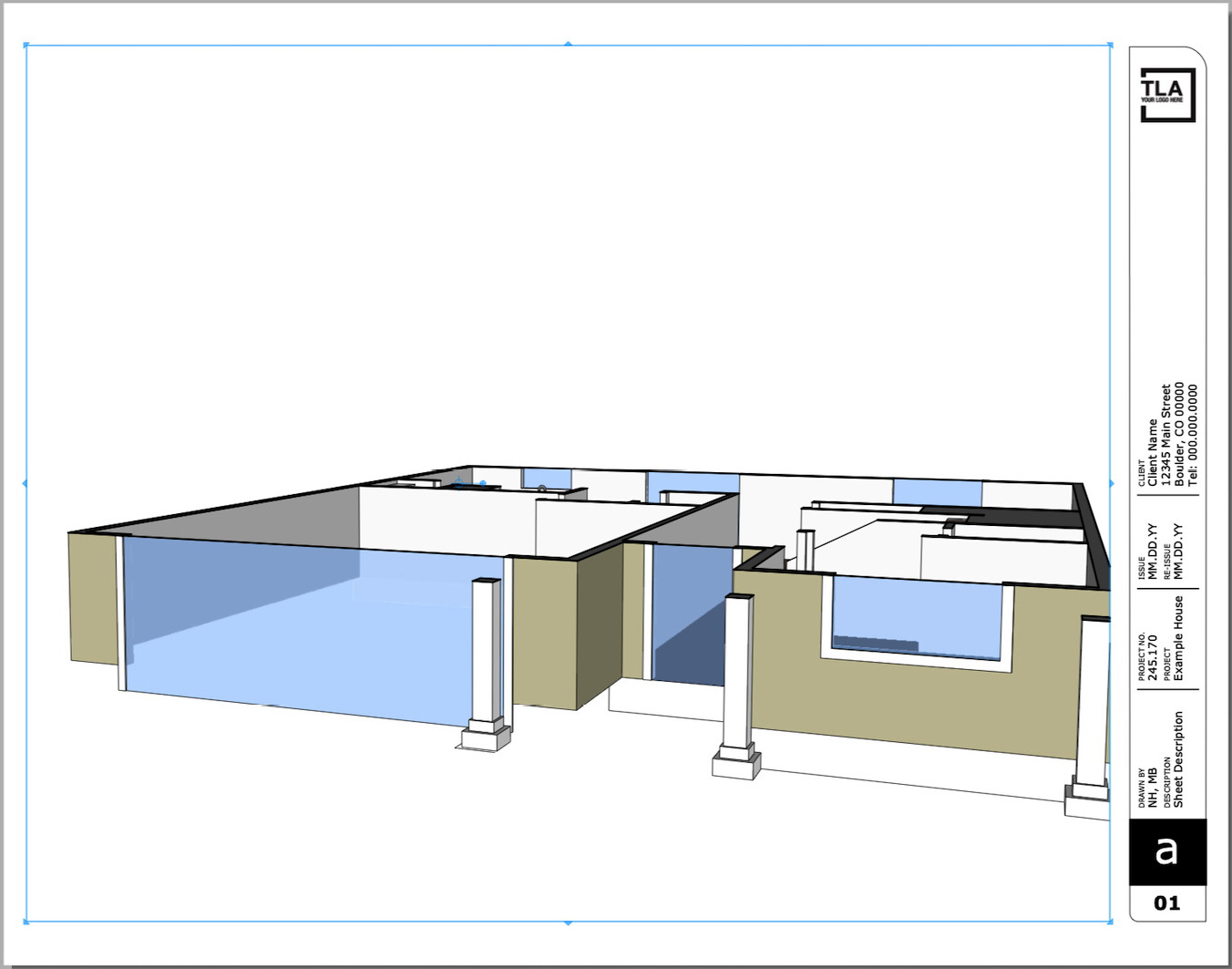
Figure 14.15 – Changing the scene causes issues with our SketchUp model viewport
The problem we are seeing is because we changed our camera setup in the copied SketchUp model viewport. When we double-clicked into the viewport and changed the view of the model, we told the camera not to be where the scene said it should be. Right now, the camera is in that same user-defined location, despite having changed scenes. Fortunately, the fix is very easy.
- Click the Reset All button in the SketchUp Model panel, then click Render.
This puts the camera back where the scene says it should be, and re-rendering the viewport gives us the view from above that we would expect in a floorplan.
Now that we have the view we want, let’s set a scale for this drawing.
- With the viewport selected, expand the Camera section of the SketchUp Model panel.
- Click the Scale dropdown (to the right of the Ortho: checkbox) and choose 1/8” = 1-0’ (1:96).
- Make sure that both the Ortho: and Preserve Scale on Resize boxes are checked, then click the Render button.
You should have a page that looks like this:
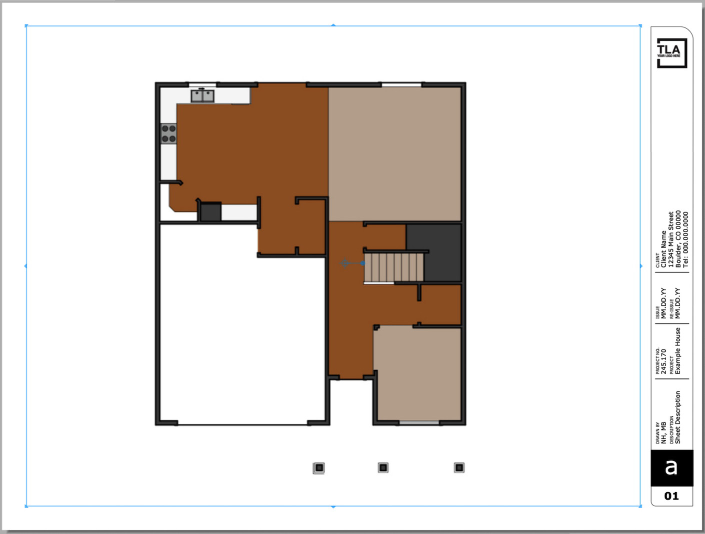
Figure 14.16 – Scaled floorplan
The drawing is smaller on the page, but if we had to manually measure anything from a printed version, we could be assured that it would be the proper scaled measurement.
Let’s keep going!
Editing the page description
Now, let’s change the page description on the title block, add a few dimensions, and add a title and scale callout to the drawing. First, we will look at editing the Sheet Description text:
- Use Select to click on the words Sheet Description.
Before we change anything, notice that the text highlights with a light blue box. Look at the Layers panel while this text is selected. Notice that the Unique Elements layer has a little light blue box next to it. This is an indicator that the selected element is on this layer.
Next, let’s add some dimensions to this drawing.
Adding dimensions
I will walk you through creating the first string of dimensions across the top of the page, then let you get through the rest of the dimensions on your own (I know you can do it). The first thing we are going to do before we draw a single dimension is create a layer to put them on (this will make them easier to edit or remove if needed). Follow these steps:
- In the Layers panel, click the + button.
- Type Annotations, then press the Enter key.
- Drag this new layer to the top of the list of layers.
We now have a layer where we can place all of our annotations (dimensions, text, callouts, and so on). Make sure that this layer is active (the active layer has the little pencil icon next to its name) as we add annotations to the drawing.
- Start the Dimensions tool either by choosing the commands from the Tools menu or clicking on the button on the toolbar.
To simplify this first example, I will refer to the points on the back wall according to the following diagram:
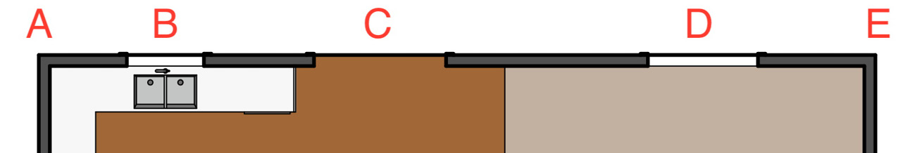
Figure 14.17 – Points we will be dimensioning
- Click on point A, then again on point E (inferencing should give you a small green dot at either point).
The first two clicks will pick the points to dimension between. The third and final clicks will allow you to place the dimension line.
- Click again a little way above the back wall (make sure there is enough space to place another dimension line between this dimension and the wall) so that you get something like this:
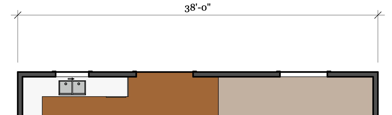
Figure 14.18 – Overall dimension on the back wall
This looks good so far! Let’s add another row of dimensions along the back wall from the ends of the wall to the center of the door and windows.
- Click point A, and then point B (referencing the midpoint of the window opening).
- Click again to place the dimension line halfway up from the wall to the existing dimension.
This will give you the start for the second string of dimensions:
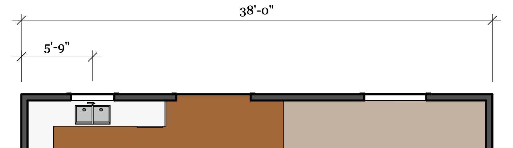
Figure 14.19 – Dimensions to the center of the first window
Now, let’s add another dimension (from the center of the first window to the center of the backdoor). To keep this string of dimensions aligned, we are going to draw this dimension backward.
Drawing the dimension backward (from the “next point back to the previous point”) makes it much easier to pick the third point and have the new dimension align perfectly with the previous dimension.
- Use this method to draw a dimension from the center of the door to the next window and from the window to the end of the wall.
When you finish, you should have a string of dimensions that looks like this:
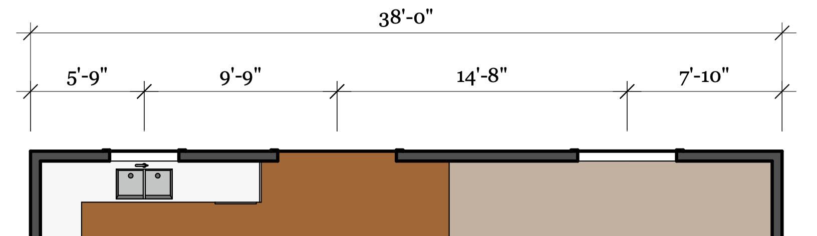
Figure 14.20 – Final dimensions along the back wall
When you finish, you should have a set of dimensions that looks like this:
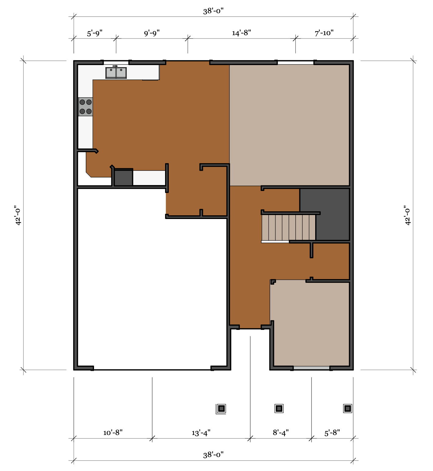
Figure 14.21 – Final exterior dimensions
Our floor plan is looking great! Let’s add one more touch so that we can call this floor good!
Adding door and window callouts
Let’s add a few callouts for the doors and windows on this floor. We will add labels for each door type in a circle and windows in hexagons. We will start with the front door:
- Select the Circle tool from the main toolbar.
Before we draw the circle, let’s make sure that it is going to be drawn the way we want. We will set the properties of the circle using the Shape Style panel.
- Open the Shape Style panel.
- Make sure that the Fill and Stroke buttons are turned on and that Pattern is turned off. The Fill color should be white, and Stroke should be set to black. If this is not the case, click on the color swatch and choose the proper color from the colors window.
- Now, draw a circle, just like you would draw one in SketchUp, just above the front door.
Assuming you followed every step, you should have something that looks like this:
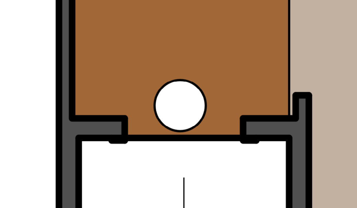
Figure 14.22 – A simple circle above the door
Next, we need to add some text to this callout.
- Choose the Text tool and double-click on the center of the circle. Then, type A and press the Enter key.
Double-clicking when you are using the Text tool sets the point where you want to start typing. You can also use the tool to drag out a text window that you will fill with text. In this case, we set the start point and then typed a letter starting at that point. Based on your current settings, this text may be too big or too small for the circle we created (most likely too big). Let’s change the font size and get it centered with the circle.
- Use the Select tool to highlight the text we just created.
- Click on the Window menu and choose Text Style if you are using Layout on a Windows computer, or Show Font if you are working on a Mac.
- Use the Font window to increase or decrease the size of the font so that it will fit into the circle, then close the window.
Now, we just need to get the text aligned with our circle. We could use Select to highlight the text and then drag it so that it mostly lines up with the circle, but there is a quicker and more accurate way.
- Use the Select tool and the Shift key to multi-select both the circle and the text.
- In the Arrange menu, click on Align, and then Vertically.
- Again, in the Arrange menu, click Align, and then Horizontally.
This will center the circle and the text vertically and horizontally. The last step here is to move it so that both items together are centered over the door they are calling out. Let’s make sure that they stay connected by putting them into a group.
- With the text and circle still selected, right-click on them and choose Make Group.
- Now, use the Select tool to drag the callout so that it is above the center of the door. Note that you can use the left and right arrow keys on your keyboard to fine-tune the placement.
This works perfectly for this door, but we are going to need a callout on every door on the first floor! We will do this by copying the current group and placing a copy at each door.
- Use the Select command with the copy modifier (Control on Windows or Option on macOS) to select the callout group and start to drag it away from the front door to the next doorway.
There are eight total doors on this floor. Use the Select tool with the copy modifier to place the callout group at each of these locations:
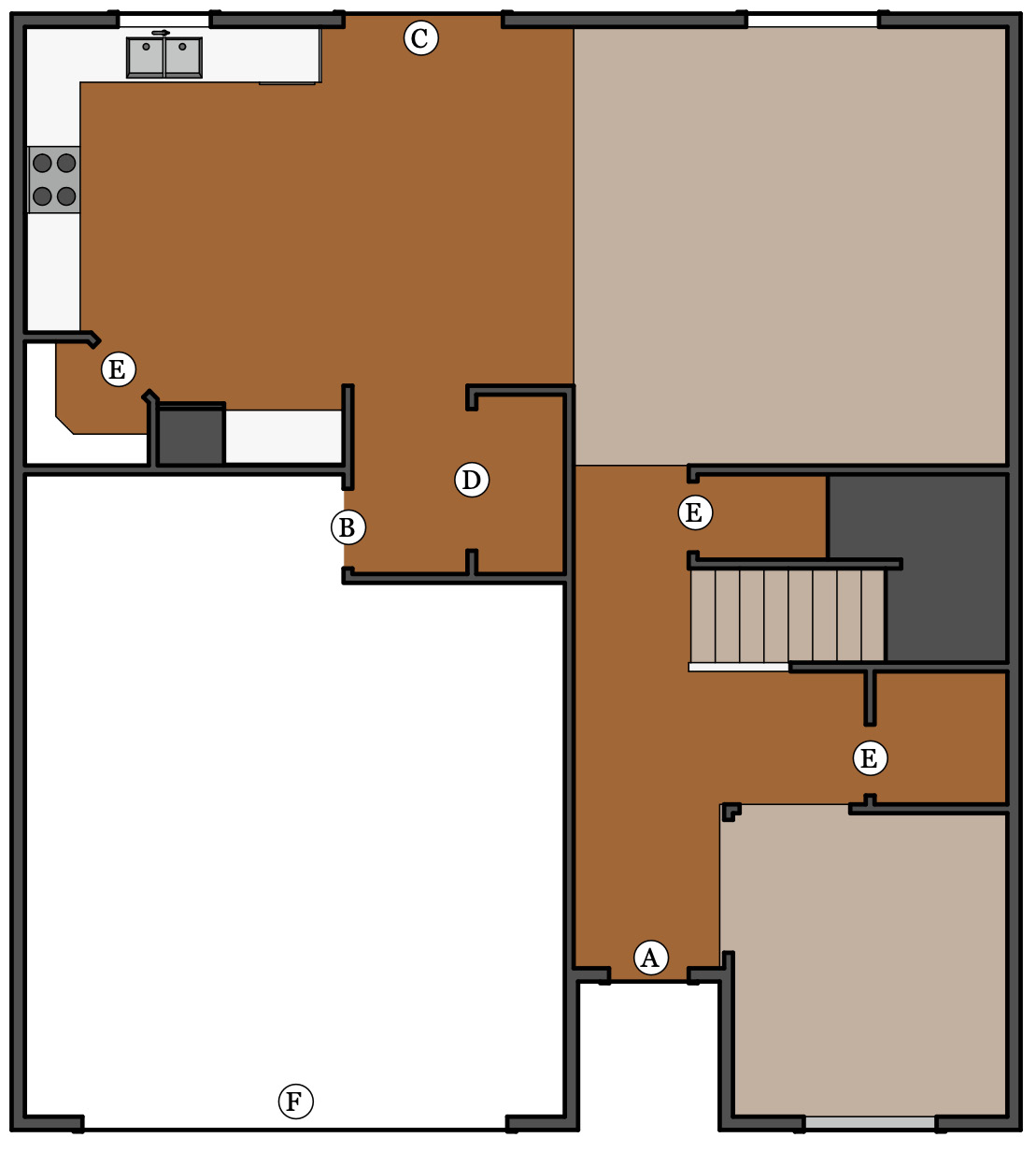
Figure 14.23 – Door callout locations
Once you have placed all the callouts, you need to change the text in the circles based on the door. Use Figure 14.23 to place unique callouts for each door size.
- Use Select to double-click on a callout group. Double-click again to enter the text box. Then, type the letter for that door.
- Click outside of the group two times (one to close the text box and a second time to close the group) to finish.
There are only three windows on this floor, so we will need a second callout for windows. For this one, let’s use a hexagon symbol with a number callout.
- Use the Polygon tool and the Text tool to create and place a new group next to each of the windows, as shown here:
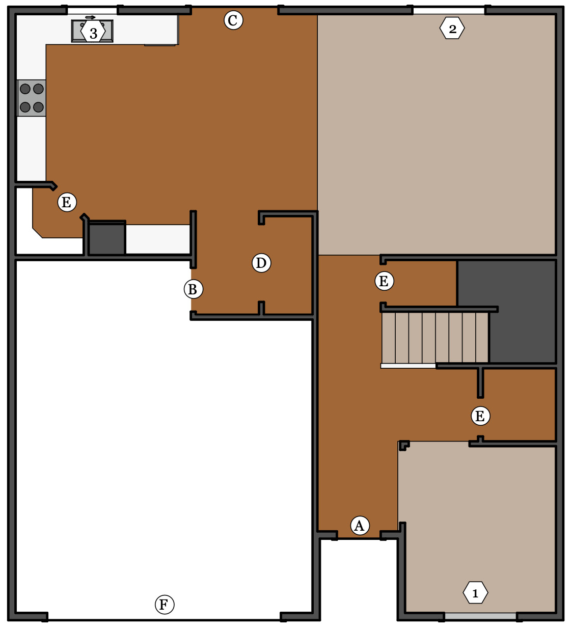
Figure 14.24 – Three window callouts
LayOut’s Polygon Tool
Between using the Circle tool in LayOut and using the Polygon tool in SketchUp, you will probably figure out how to use this tool with little issue. I did want to point out that to increase or decrease the number of sides, you can tap the Up or Down arrow keys as you are drawing the shape. Also, holding down the Shift key will make it easier to keep the shape on the axis.
This page is looking pretty close to done, but we need to add a title to our drawing.
Adding a page title
Now, let’s drop a title for this drawing onto the page along with a scale callout:
- Expand the Scrapbook panel.
- From the dropdown at the top, choose TB-Traditional and then Drawing References.
What we want to do here is drag a copy of the drawing title at the bottom of the panel onto our page. The one we are looking for looks like this:
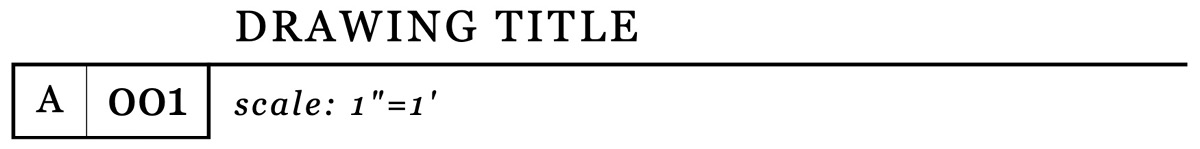
Figure 14.25 – The drawing title from the scrapbook panel
- Click and drag the drawing title from the bottom of the Scrapbook panel to the page, right below our dimensioned drawing.
When you drop an item from a scrapbook, you are simply placing LayOut items into your drawing. In this case, this is a group that contains lines, rectangles, and text. We can edit any of these items by double-clicking on them. Let’s customize the information in the new group to show the appropriate drawing title and scale.
- Use the Select tool to double-click on the group.
- Double-click on the DRAWING TITLE text.
- Replace the text with First Floor Plan and then click outside of the text box.
- Double-click on the scale: 1”=1’ text.
- Change 1” to 1/8”.
- Click outside of the text box twice.
You should now have a drawing title that looks like this:
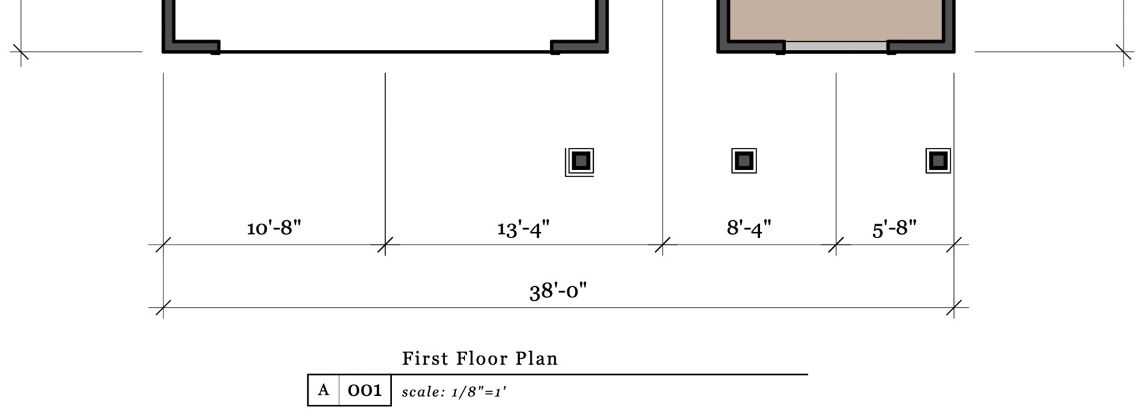
Figure 14.26 – Edited drawing title
Our plan is coming together at this point! Let’s use this page to create a second floorplan.
Creating a second floorplan
While we could start a new page from scratch, as we did with the first floorplan, it is often easier to duplicate pages than make changes where appropriate to save time.
Before we get into duplicating the page we have been working on, let’s make sure we give it an appropriate name. If you look in the Pages panel, you will see that we have two pages. The one we are currently working on (the one that is currently selected) is named Inside Page. This name came from the template and is different from the Cover Page. Let’s change the name real quick:
- In the Pages panel, click on the Inside Page text and replace it with 1st Floor Plan. Then, press Enter.
Next, let’s make a duplicate of this page, rename it, and then start editing it to represent the second floor.
- With 1st Floor Plan still selected, click the Duplicate button (this is the button between the + and – buttons at the top of the Pages panel that shows the two pages):
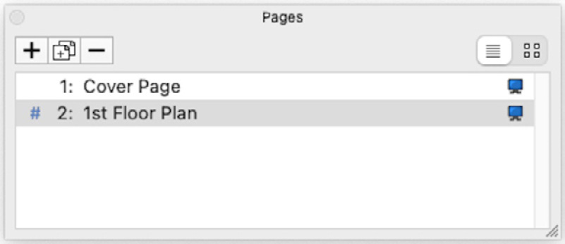
Figure 14.27 – The Pages panel
Now, when we look at 2nd Floor Plan, it will look just like the 1st Floor Plan page. Let’s make some changes! First, let’s change which scene is being shown in the viewport.
- Use Select to highlight the SketchUp Model viewport.
- In the SketchUp Model panel, change 1st Floorplan (traditional) to 2nd Floorplan (traditional). Then, click the Render button.
The model looks good – it is in the same location and the scale is the same, but the annotations are a bit of a mess. Since these were all placed based on the geometry of another floor, let’s go ahead and wipe most of these annotations out so that we can start from scratch. I say most of the annotations, because it may make sense to keep one door callout and one window callout rather than recreate them on the new page.
- In the Layers panel, click the little lock icon to the right of every layer except for Annotations.
- Use the Eraser tool to remove the dimensions and door and window callouts (saving one of each callout if you like).
- Unlock all of the layers and edit the drawing title so that it reads Second Floor Plan.
- Finally, let’s change the title bar on the side of the page so that it reads Second Floor.
With that, you should have a new page that looks something like this:
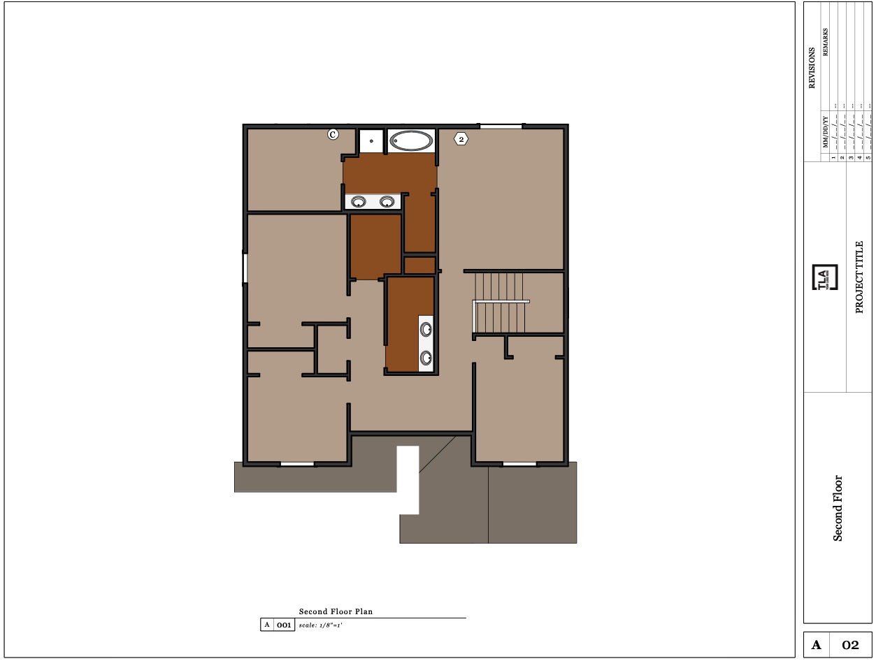
Figure 14.28 – Second floor plan page
At this point, you are ready to add new annotations and additional information specific to the second floor.
There are so many more things we could do to turn this example into a full set of plans. We could add tables referencing the door and window callouts. We could add notes from text files with information about the design or site. We could pull in an entourage from the scrapbooks. The point is that this chapter was just an introduction to what LayOut can do. If you want to keep using SketchUp, try adding more pages to the document (you can create elevation and section pages) or create a brand-new LayOut document using your own SketchUp file.
Now that we have a general idea of how we would go about creating a set of drawings from LayOut, let’s spend just a little bit of time learning about where we can take these drawings.
Generating output
It sure feels good to get a nice drawing put together from a SketchUp model, but now, we need to get these pages out into the real world! There are three options when it comes to generating output from LayOut – printed drawings, digital drawings, and file exports. Let’s explore why we may want any one of these types of output and touch briefly on how to generate them.
Generating printed drawings
For years and years, hard copy drawings have been a staple of almost every fabrication or building industry. In the world of building design and fabrication, these started as hand-drawn images that were eventually replaced by computer-generated 2D imagery. As much as we all talk about “going paperless,” the fact is that many workflows end with someone somewhere printing out a stack of paper that represents the process that needs to be performed to transform a 3D model into reality. If you find yourself needing that stack of paper, LayOut has you covered.
Once you have finished creating your document in LayOut, printing is as simple as clicking File, and then Print…. Depending on your operating system and system setup, you will be prompted to choose the printer you want to send your drawings to. LayOut uses your computer setup to find a valid printer, so make sure that you are connected to a printer before trying to output your document.
If you are not connected to a printer or plan to use a third-party printing service, you may want to generate digital drawings.
Generating digital drawings
In addition to being perfect for sending to your neighborhood print shop to generate large format hard copies, digital drawings are great for sending to co-workers, clients, or other stakeholders of your project. Digital documents are also a nice way to generate output when you are going through design iterations and will be creating multiple versions of the output. Plus, since you do not need to wait for pages to be physically printed, digital output tends to be much faster to create.
Regardless of the reason for needing digital plans, you will likely want to generate a PDF file. A PDF file is pretty well accepted as the standard for digital drawings and can be opened and viewed on most devices. Additionally, once generated, there is a slew of ways to edit, annotate, or even lock your files before sharing them with others. How you generate a PDF will depend on your operating system.
Creating a PFD in Windows
To export a PDF file of your document, choose Export from the File menu, and then select PDF… From there, you can specify the file location from the Export PDF window and choose Save. There are no options in this dialog because the PDF is generated using the settings that were used to create your document. Things such as page size are taken from the template you used to start your LayOut document.
Creating a PDF file in macOS
There are two ways to generate a PDF in LayOut for macOS. The easiest is to use the Print dialog. When you choose the Print… command from the File menu, you can click the PDF dropdown at the bottom of the window. This will give you options for exporting a PDF file, and even creating and emailing the file directly from the Print dialog.
While it is great to be able to generate a PDF file that almost anyone can view, there may be cases in which you are working with someone who needs a file that they can use in their design software. This is where exporting a file comes into play.
Generating file exports
Exported files are different from the PDF file we just walked through. This process is all about generating a DWG or DXF file for use in another drawing or design software. Where PDF files can be viewed by a large group of people on most devices, DWG and DXF files can be imported and used as reference or linework in software that’s specific to most design industries. Like exporting a PDF, the process of exporting a DWG/DXF file is different, depending on your operating system, and includes more options than a PDF export.
Exporting a DWG/DXF file in Windows
Exporting a DWG/DXF file from LayOut for Windows is as simple as choosing Export from the File menu, then clicking DWG/DXF.... In the dialog that appears, specify the location and name of the file you wish to export. As soon as you click the Save button, you will be prompted with the DWG/DXF Export options window:
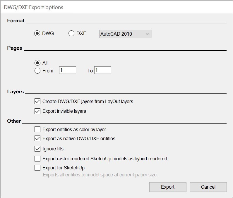
Figure 14.29 – The DWG/DXF Export options window on Windows
Use this window to specify the exact file format and drawing options you need for the file you are exporting. These options may change based on how the file will be used once created.
Exporting a DWG/DXF in macOS
To export a DWG/DXF file while in LayOut for macOS, click the Export option in the File menu. In the dialog, specify the location and filename and choose DWG/DXF from the Format field at the bottom of the window. Clicking the Save button will immediately export the file. If you want to modify the settings that will be used to generate the file, click the Options… button to bring up the DWG/DXF Export options window:
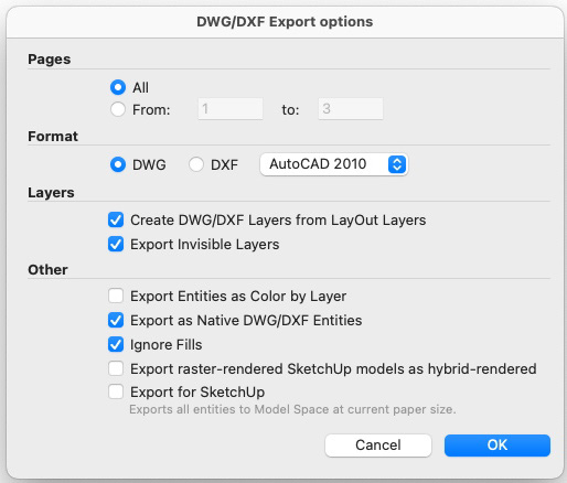
Figure 14.30 – The DWG/DXF Export options window on macOS
Use this window to specify the exact file format and drawing options you need for the file you are exporting. These options may change based on how the file will be used once created.
With that, we have covered the basics of exporting printed or digital drawings and files.
Summary
LayOut is a great resource and a wonderful tool for generating documentation from your SketchUp models. This chapter was a very high-level overview of its capabilities and intended to introduce you to what is possible. I highly recommend looking into additional training on LayOut if you plan to use LayOut in a production setting. It is a great tool but does require more instruction than I was able to present here, in this chapter.
In this chapter, you learned how you should think about setting up your SketchUp file for use in LayOut, how to import and add annotations to a SketchUp model, and finally what you need to do to generate output.
In the next and final chapter, Chapter 15, Leveraging the SketchUp Ecosystem, you will learn how to best leverage all of the tools that are included with your SketchUp subscription and the other resources that are available to you right now.