
2
Organizing Your 3D Model
Hopefully, the last chapter prompted you to rethink how you might use the SketchUp commands when you create a 3D model. With this chapter, I am hoping you will rethink how you structure your 3D models.
Generally, it is very apparent when someone with experience creates a 3D model versus someone just starting off. A well-organized model demonstrates a modeler’s experience and ability to think through their model as they go. A model that is put together in a structured manner is not just easier to look through, but easier to work with, as well! Whether this model will be passed to a co-worker or collaborator at some point in the future, or it is you who will be coming back to make revisions six months after your final save, if a model is well laid out, it will save time and energy!
In this chapter, we will construct a model of a dining table complete with place setting and chairs. Each piece will be added to the model in an organized manner, making it quick and easy to return and make changes as needed. This will serve as a template for how your models should be put together in the future.
In this chapter, we will cover these main topics:
- Mastering Groups and Components
- Getting more out of tags
- Understanding the Outliner
- Using scenes for more than appearances
- Removing model excess
- Using visibility commands
Technical requirements
This chapter will assume that you are using the newest version of SketchUp Pro. You will also need to download the model Taking SketchUp Pro to the Next Level – Chapter 2.skp from 3D Warehouse:
Mastering Groups and Components
By this point, we have already reviewed how important it is to use Groups and Components to separate geometry. I would say that one of the very worst things a SketchUp user can do when they create a 3D model is to ignore Groups while modeling. I have downloaded many models from 3D Warehouse only to find that they are monolithic blobs of geometry, nearly impossible to edit or manipulate due to all the geometry being merged. Using Groups to separate the “pieces” of your model is not an intermediate or advanced process, but simply how you should be doing things from the start.
Starting with Groups
Before diving into when and where to use Groups and Components, let’s touch on a single command that may help you organize every model you work on from this point forward: Make Group.
I know, you have used the Make Group command in the past and it’s not a “new” command, but I would like to suggest you think about using it in a new way. To simplify your modeling process and to help you keep things organized, use Make Group before you start modeling.
Try this:
- Open a brand new SketchUp model.
- Right-click on the blank screen.
- Click on Make Group.
At this point, it may seem as if nothing has happened, but you are currently looking at an empty Group. Anything you draw at this point will be a part of this new Group.
See how the Group indicator appeared around your new rectangle as soon as it was drawn? Creating a Group before you start drawing ensures that this geometry will not only be separate from edges and faces drawn in the future but will allow you to quickly place this Group into the proper tag or convert it into a Component as needed.
Make Group can be used any time you create geometry in SketchUp, not just when you are starting a new model. Let’s add another Group to this Group.
- Use Push/Pull to pull this rectangle up into a box.
- Use Select to click outside of the Group.
Closing a Group
Selecting outside of a Group will close the Group. If you don’t want to change commands to Select to close a Group, you can right-click in the empty space inside the Group boundary and select Close Group from the context menu.
- Right-click anywhere other than the box you just created and choose Make Group.
- Draw a circle on the side of the box in the previous Group and use Push/Pull to pull it out into a cylinder.
- Close this new Group.
You now have geometry in two separate Groups. Using Make Group at the beginning of the modeling process means that you don’t have to mess with any selection acrobatics to highlight the edges and surfaces you want in each Group if you had done so after the geometry was created.
You probably noticed that when you right-clicked, you had the option of choosing Make Component… as well. So why did we use Make Group in the previous example? This was one of those times where we used the simplified command for the sake of instruction (Make Component… brings up a dialog that I did not want to cover, at this point, so Make Group was used). If you know that you want to create a Component, then do so from the start! If you are not sure when to use Groups or Components, then read on!
Groups versus Components
Groups and Components are collectively referred to as Objects in SketchUp and both serve the basic functionality of separating geometry from other geometry. Additionally, Components have some extra functionality that makes them special (sorry, Groups, but it’s true). In addition to being a container for geometry, Components also have additional functionality:
- Component copies are connected; change one, you change them all.
- Components have the ability to store additional user-defined information or ICF file data.
- Components can be used to create Dynamic Components used to add additional behavior or data.
This list contains all the reasons you should consider using a Component when you create an Object. Generally, my thought process on when to use a Component looks something like this:
- Will this Object repeat through my model?
If yes, use a Component.
- Do I need to report upon and information of this Object (things such as material, length, price, and so on)?
If yes, use a Component.
- Am I making a Dynamic Component?
If yes, use a Component.
If you answered no to all of these questions, you are probably safe to make a Group. The good news is, if you decide later on that you want a Component, you are only one right-click away from converting your Group into a new Component.
It should be noted that there are those who make everything a Component. While there is an argument to be made for this, as copies of Components will end up creating a smaller overall file size than the same number of Groups in a file, one of the nice parts about using a Group is that it involves just a single click or shortcut key and you are done. Creating a Component will always require that you fill out information in a dialog.
Naming Components
Skipping the Component information and just clicking the Create button is tempting, but we are in a chapter on keeping our work organized, so let’s commit to a simple rule: All Components get a descriptive name. No exceptions! For that matter, it is not a bad idea to name Groups, either.
I tend to lean toward my own simplified set of rules for Component creation. In this setup, every “thing” is a Component. Any time I want to keep a set of Components together, they go into Groups.
Nesting Groups and Components
Nesting is simply the act of putting a Group or Component inside of another. This is a great way to keep your model organized. Any time you create a set of Objects, placing them inside of another container will make your model much easier to work with and make the process of copying or editing geometry much easier.
As we discuss nesting, we should address the previous question in this new context: when nesting, should you use Groups or Components? Once again, a lot of this comes down to personal preference, but I will offer a simple suggestion: if this collection of Objects needs to be reported upon or if it will be copied and you want the copies to be the same, use Components. Here is a visual example of combining.
Let’s get hands-on with an example:
- Open the model Taking SketchUp Pro to the Next Level – Chapter 2.skp.
- Open the Component window.
The Component Browser
Another benefit of modeling with Components is that they show up in the Component Browser window. From here, you can simply drag and drop Components saved in the file into your modeling window. Unlike Groups, Components can exist in your model without being on the screen. This is another way to keep your model organized.
- Drag the Salt Shaker Component onto the table.
- Drag the Pepper Shaker Component onto the table, next to the Salt Shaker Component.
Right now, you have two Components sitting on a third (the table). At this point, you could say you are done with the model and move on, but let’s say you want to ensure that the two shakers stay next to each other. To do that, we will put them into a Group.
- Select both the Salt Shaker and Pepper Shaker Components.
- Right-click and choose Make Group from the context menu:
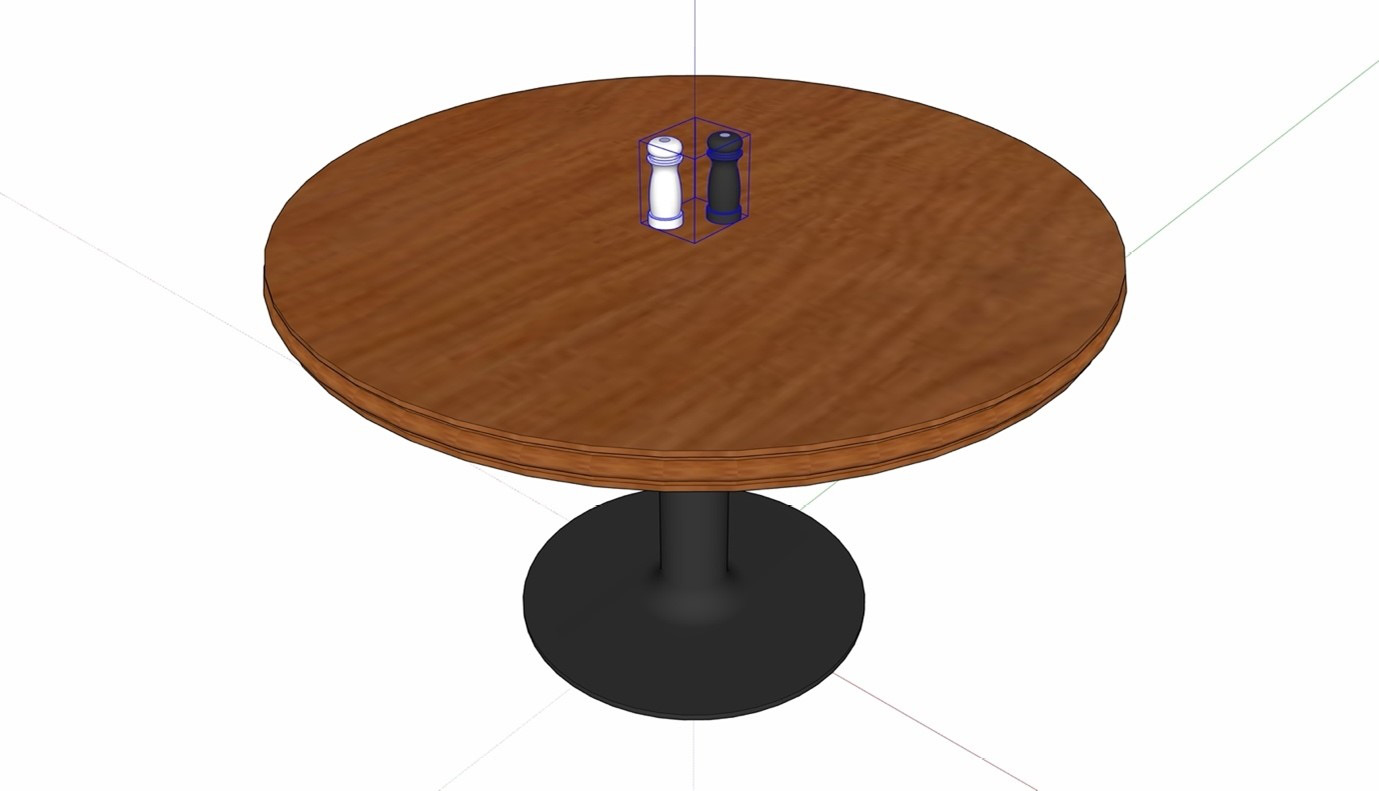
Figure 2.1 – These two Components are now held together in a single Group
In this case, it makes sense to use a Group to keep these Components together since that is the only function of the container.
There are of course exceptions to every rule, and this one is no different. There are cases where you may want to place Components into other Components.
- Arrange the Fork, Knife, Spoon, and Plate Components on the tabletop.
- Select all five Components and right-click.
- Choose Make Component… from the context menu.
- Name this Component Place Setting, then click Create:
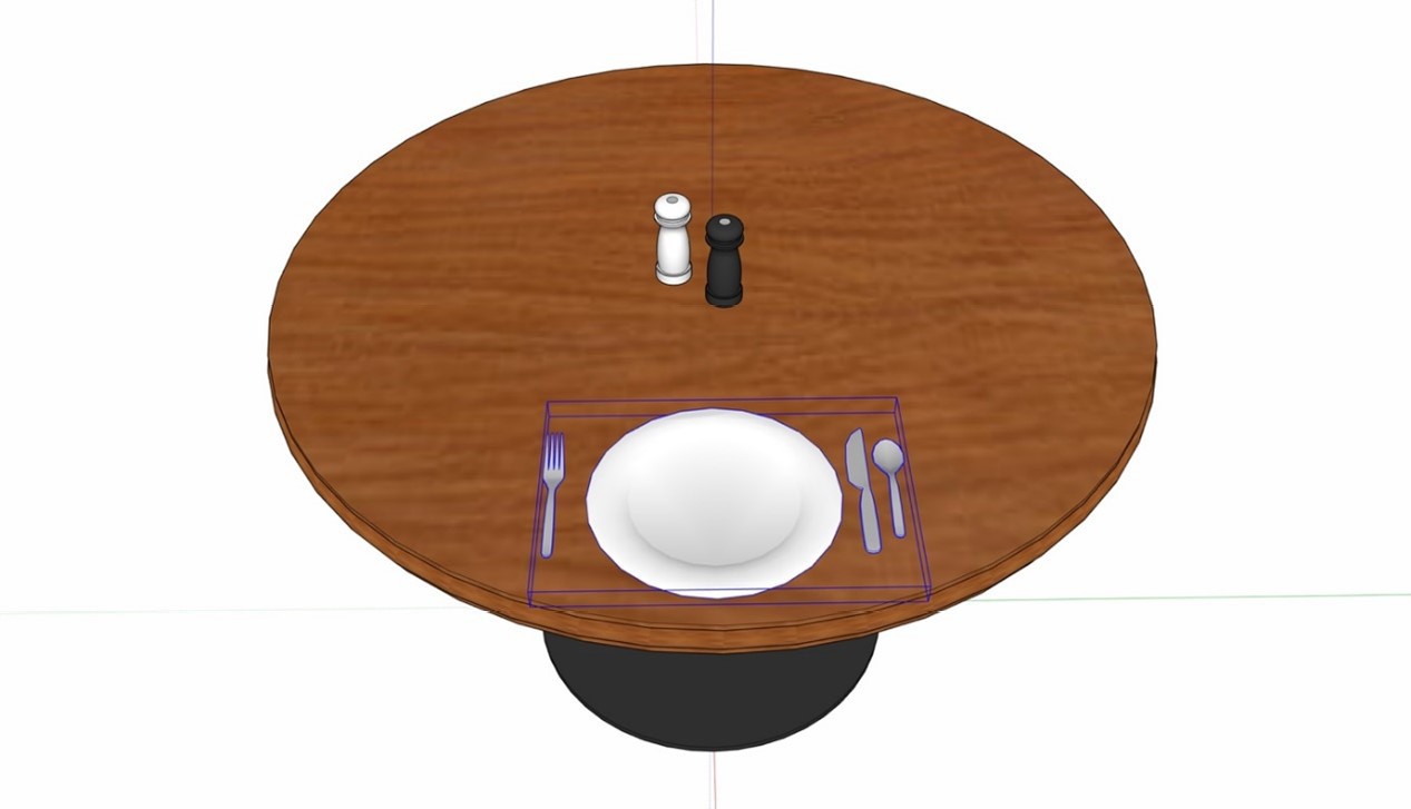
Figure 2.2 – Table for one
Now, why did we make this a Component rather than a Group? In this case, we want to make a few copies of the Place Setting around the table.
- Use the Rotate command to make a radial array of the four Place Settings Components around the table.
Great! Now our table is set, but as often happens when designing in the real world, the requirements for this model have changed. Let’s say the client has requested that you add a salad fork to the Place Setting. Since we made the Place Setting a Component, we can add the salad fork to all four instances of Place Setting easily!
- Double-click on one of the Place Setting Components to open the Component.
- Drag the Salad Fork Component next to Fork.
- Close the Place Setting Component.
Notice that all four settings get updated. This is using the power of Components along with nesting to simplify the process of working on your model and keeping it nice and organized, as shown here:
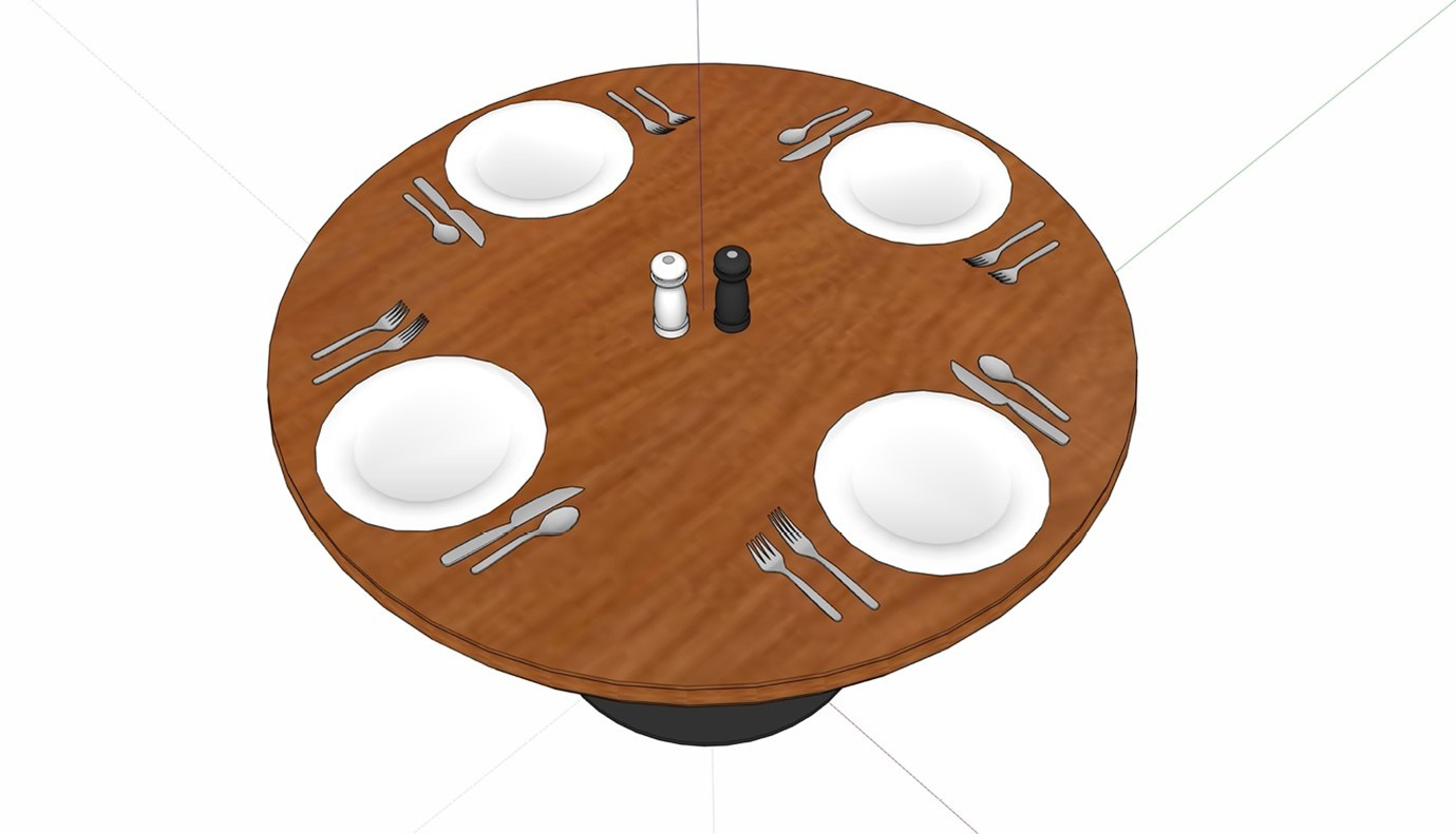
Figure 2.3 – A perfect table for four
Let’s finish this table up with some chairs.
- Drag a Chair Component from the Components window and place it in front of one Place Setting, then use Rotate to make an array four chairs in total around the table.
- Select everything (the table, chairs, shakers and place settings) and place them into a new Component called Four Top.
- Now make a copy of that Component along the red axis.
- Select both Components and copy them along the green axis.
- Now select all four Components and make a Group of them.
Naming Groups
While Groups will not prompt you for any information, you can give them names. Select any Group and enter a name for it in the Instance field in Entity Info.
With this, we have created a small seating section of a dining room:
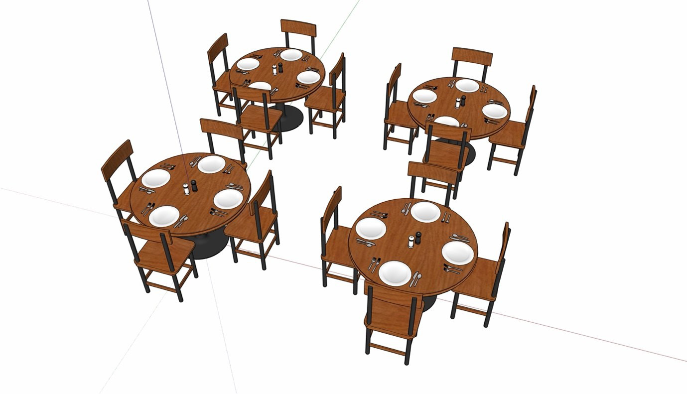
Figure 2.4 – Components in Groups in Components with Groups
If we needed to move all of these tables together, it would be as simple as selecting and editing the Component!
Remember, creating Groups and Components not only make your future job of working in this model easier by keeping things organized, but the use of Components mean you only need to edit a single instance in order to change everything. Now that we have everything organized, let’s talk about controlling the visibility of our model.
Getting more out of tags
The next level of organization you should be thinking about is using tags. Tags allow you to control the visibility of a set of Objects with a single click. One of the things that many beginners struggle with in SketchUp is limiting what is on the screen at any given time. Being able to control what you see on the screen ensures you can focus on what you are working on. Tags make it simple to control what you see and how you see it, making it easier to work with your model.
More Than Just Visibility
While, for many, the primary use of tags is to toggle visibility, tags can also be used to set line styles. Remember, if you use tags for this purpose, every edge to which you assign the tag will receive the given line style.
Let’s organize our table with some tags:
- Let’s create some new tags. Open the Tags window and click the plus icon at the top to create the following tags:
- Settings
- Condiments
- Tables
- Chairs
At this point, your Tags window should look like this:
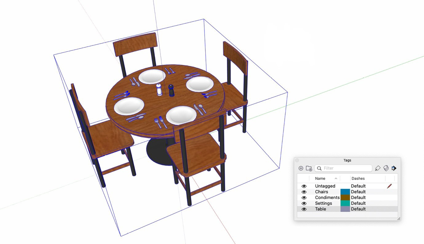
Figure 2.5 – The Tags window with tags ready to be applied
Now that you have the needed tags created, let’s assign them to the proper Objects.
- Double click the Four Top Component, choose the Tag command, then highlight the Condiments tag in the Tags window.
- Click on the Group that contains the Salt Shaker and Pepper Shaper Components.
- Next, highlight the Settings tag in the Tags window and click on all four Place Settings.
- Assign the Chairs tag to the chairs.
- Finally, assign the Table tag to the Table Component.
At this point, everything has its own tag and visibility control. Turn the Table tag on and off and you will see all the Table Components disappear. This is, again, the power of Components. Since the entire Object, which you named Four Top in the previous section, is a Component (and not a Group), you only have to apply tags to one instance and all copies inherit the tag assignments.
Only Tag Objects
Tags are great for organizing your model but be sure to only apply tags to Groups and Components. Raw geometry (all of those edges and faces) should stay untagged. Applying tags to raw geometry can create a mess of a model.
Having these tags is a great help, but if we want to turn off all the parts of our model, we need to click each tag individually. How can we make that easier? Just like Objects, tags can be nested as well. Let’s grab all the tags we just created and put them into another tag. In this case, we will create a tag folder to hold the tags we created.
- Use Shift to select all four tags.
- Click the Tag Folder button at the top of the Tags window.
- Name the new tag folder Four Top.
Now you can toggle visibility of the entire tag folder, or navigate into the folder to toggle individual tags as needed.
Downloaded Tags
Tags are saved as a part of all SKP files. This means if you import a file into your model, you are importing its tags, as well. Importing a piece of furniture or entourage from 3D Warehouse is a huge time-saver, but make sure you keep an eye on the tags that they add to your model. Get more information on working with 3D Warehouse models in Chapter 12, Using 3D Warehouse and Extension Warehouse.
Taking the time to create and assign tags to your model as you go will help to keep your model organized and make it so much easier to work with. This is true not just for you, but for others who may need to use your model as well. One of the hallmarks of a usable SketchUp model is clearly named, properly applied tags. Now let’s dive into one of the most powerful tools at your disposal for model organization, the Outliner.
Understanding the Outliner
One of the most overlooked tools in SketchUp is the Outliner window. Many users rarely, if ever, open it, much less use it in their regular modeling sessions. In case you are one of those who have not spent time with the Outliner, it is basically a list showing every Object in your model along with the full nesting hierarchy. Not only is it a display of all the pieces that make up your model; it’s also a way for you to select and toggle the visibility of everything!
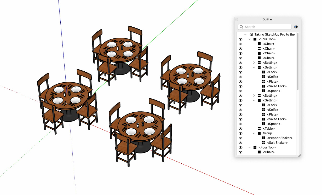
Figure 2.6 – The Outliner shows every Component and Group in the entire model
We have done a good job of creating Groups and Components and assigning tags to them, so our simple dining room is easy to work with so far, but the Outliner will let you see the state of your model as well as giving you access to items that are not individually tagged. For example, let’s say you want to turn that Salad Fork Component off. Let’s do that using the Outliner:
- Click the arrow to the left of one of the Four Top Components to expand it.
You will see each of the Place Settings Components, the Table Component, the Chair Components, and a Group that contains the Salt Shaker and Pepper Shaker Components.
- Expand one of the Place Setting Components.
- Click on the Salad Fork Component.
When you select anything in the Outliner, you are selecting that item (and in the case of nested Components, all instances of that Component) in your model. This has already saved you numerous double-clicks and orbits to get to a view of the item you want to work with. Let’s go further!
- Right-click on the selected Salad Fork Component in the Outliner.
At this point, while still in the Outliner, you have access to all of the commands you would see in the modeling window had you right-clicked on the actual Object. From here you can erase, open, or hide the Component. Let’s see what happens when you hide the Salad Fork.
- Select Hide from the context menu.
It’s gone! Well, it’s not gone, just hidden. Hide is a great way to temporarily take Objects off your model screen, but can be tricky to use because once an Object is hidden, you cannot interact with it. This causes a headache for many users because they will “lose” items in their model by hiding them and never getting them back. With the Outliner, you can see everything, even hidden items.
Notice that the Salad Fork Component is still in the Outliner, but the eye icon to its left is toggled off (and the text is light gray). This makes it very easy to right-click and select Unhide. Unlike tags, visibility in the Outliner allows you to control individual Objects and not everything as a collection. This gives you a lot more control of what you are seeing in your model.
- Right-click and select Unhide for the Salad Fork Component.
The Outliner can be used for so much more than just toggling visibility. For example, notice that the Group that contains our shaker Components is named Group. Another thing that will make your model easier for future users of this file (including future you) is giving everything a name. When Groups are created, they simply get the name Group (not having to enter information makes Groups quick and easy to use). Let’s change the name of this Group using the Outliner.
- Select the Group.
- Click again on the name field.
- Type Shakers and press Enter.
Entering Objects through the Outliner
Double-clicking on an Object in the Outliner will open that Object in the modeling window. This makes it very easy to open Groups or Components for editing without having to burrow down into your nesting hierarchy.
This chapter only scratched the surface of what you can do with the Outliner. If it is not a tool that you currently use, I would highly recommend that you start keeping an eye on it or consider using it as your model get more complicated. Not only will it help you to navigate a complicated model, but it will also help remind you to keep things organized! Speaking of organization, let’s hop into the Scenes window and see how we can use scenes to make it easier to work with our SketchUp model.
Using scenes for more than appearances
Most users depend on scenes to position the camera, or to prepare a view to be used for output from LayOut. While this is a primary function of scenes, there are other ways that you can use scenes to help you model. For this next example, let’s make a few scenes that will allow us to quickly change what is visible in your model:
- Open the Scenes window if it is not already open.
- Click the Show Details button to show all the options for scenes.
In this portion of the window, you can do some basic functions including naming the scene or specifying that scene should be in an animation, and it also includes all of the properties that will be saved with the scene. By default, all the listed properties will be saved with the scene and restored when a scene is activated. By choosing to turn on only some of the properties, we can create scenes that help during the modeling process.
For example, let’s create a scene that hides all of the Place Setting and Shaker Objects on the table. This is something that you may want to do to optimize your file as you model. Remember, the number of things on the screen at any given time will affect how SketchUp performs. Making a scene with detailed items turned off that you can quickly switch to lets you speed up SketchUp when needed.
- Turn off all checkboxes except for Visible Tags.
- Verify that all tags are currently visible, then click the Add Scene icon (the plus at the upper left of the Scenes window).
Since we created this scene with everything visible, this is our “all on” scene. Enter the name All On and press Enter.
- Now turn off the Settings and Condiments tags.
- Click the Add Scene icon again and rename the new scene to Empty Tables.
You now have two scenes that you can use to display or hide all the stuff on the table. Click back and forth between the two scenes and see how easy it is to make the change to what’s visible in your model. Clicking the All On scene will show everything in the model:
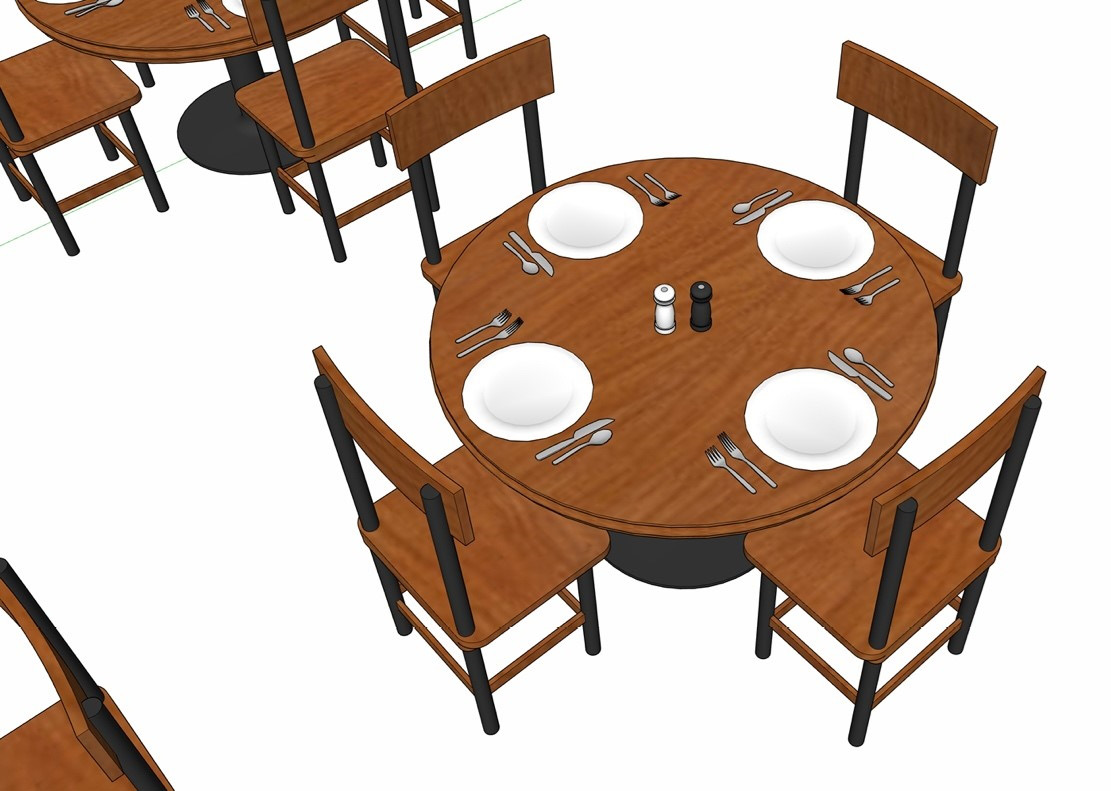
Figure 2.7 – All On scene
If at any point you want to see just the tables and chairs, you can hide everything on top of the tables by clicking the Empty Tables scene:
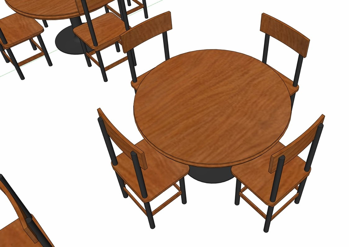
Figure 2.8 – Empty Tables scene
Note that you can orbit around the model and still switch these scenes. Since there is no connection between the camera location and the scenes, you can jump between them without having to worry about your point of view changing.
So, we know that we can use scenes to move the camera and create views for modeling or output, and we can also tie scenes to tag visibility, but let’s try making a scene with another property. We will now create a couple of scenes that change how the Objects appear on screen:
- Click the Add Scene icon.
- With this new scene highlighted in the Scenes window, turn Visible Tags off and turn on the Style and Fog property and the Shadow Settings property.
- Click on the Update Scene(s) icon (just left of the Add Scene icon). Click Update.
- Name this scene Standard Style.
- In the Style window, choose the Monochrome style.
- In the Shadow Settings window, turn shadows on.
- Click the Add Scene icon.
- Name this scene Mono Shadow.
You now have four scenes that allow you to control what is visible and how it looks. At this point there are four states you can create by combining these four scenes:
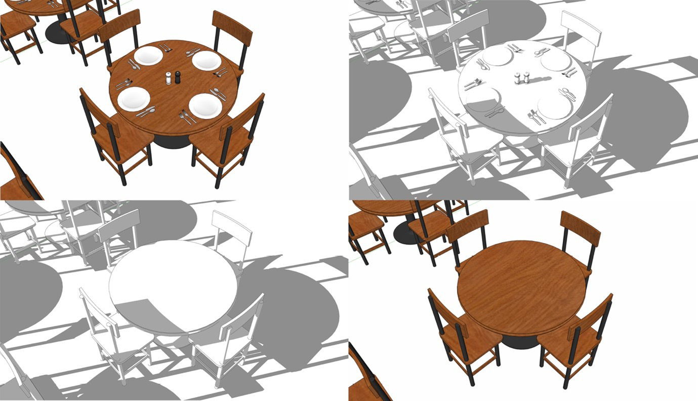
Figure 2.9 – Four scenes create four possible views of your model
We are using our scenes as controls to quickly toggle properties of our model. Those of you reading this book who are good at math may be looking at this thinking, “I have four scenes that allow me to view my model four ways, so how is this an advantage of creating four scenes?”
That is a great point. The real advantage happens when we add another control using scenes. Let’s make a couple of scenes that allow us to toggle off the chairs:
- Click the Add Scene icon.
- With this new scene highlighted in the Scenes window, turn the Style and Fog and Shadow Settings properties off and turn on the Hidden Objects property.
- Click on the Update Scene(s) icon (just to the left of the Add Scene icon). Click Update.
- Name this scene With Chairs.
- In the Outliner, open the Four Top Component and toggle visibility off for the four Chair Components.
- Click the Add Scene icon.
- Name this scene No Chairs.
You now have a set of controls to turn the chairs on and off. When you combine this control with the previous setup, you can now create twice as many views of your model:

Figure 2.10 – Six Scenes create eight possible views of your model
See how the ways to view your model grows? And we are only using a few properties! With more variations of the properties (such as multiple scenes with different tags visible, or more style scenes), you can create dozens of views with just a few scenes.
Remember, scenes do not have to be binary. When using the default scenes (with all properties enabled) you create scenes that force everything when they are enabled. By choosing to only enable some of the properties in a scene, you can create view controls that can be used together!
You have now learned a lot about organizing and controlling the view of your model, which is an essential skill for creating an optimum SketchUp file. Another important ability of a great modeler is to get rid of the excess.
Removing model excess
Many new SketchUp users have started playing around with a model, making it bigger and bigger, trying out commands and just seeing what they can make, when the model starts to slow down. This can become apparent when saving or opening the model (long load times) or when orbiting the model (jerky or lagging movement through the model). While hardware can impact this (a brand-new desktop computer with 64 GB of RAM will handle a larger model than a 10-year-old laptop with a quarter of the RAM), a model that is free from excess data will behave much better than a model with extra, unneeded data.
Up to here, we have talked about keeping your geometry organized with Objects, controlling visibility with tags, using scenes to create quick toggles to change how your model appears on the screen, and finding Objects in your nesting structure with the Outliner. These are great ways to create and organize your model; they do not, however, help you to prevent your models from becoming bloated and hard to work with.
While steps have been taken in recent releases to minimize file size and speed up the modeling process, a simple fact remains: an organized, optimized model will perform better than a messy, bloated one. Using what was just covered will help to keep your model organized, but this section will look at how to optimize your model.
Something that is very important to remember is that a SketchUp file (.skp) is made up of more than just what is on your screen. An .skp file includes the geometry and colors that you see on the screen, and so much more! Every file you create includes the following:
- Geometry (faces and edges, hidden or visible)
- Materials (including imported imagery)
- Group and Component information
- Tags and scenes
- Styles
- Model info (such as units, text default, and the author)
- Geolocation information
- And all the other stuff you may add during modeling (guides, sections, dimensions, text, and so on)
In this section, we will look at how to clean up a model if it has gotten out of hand. We will start, however, by thinking about creating models with the least amount of geometry necessary.
Optimizing geometry
While we have established that there is a lot of data that goes into a SketchUp file, let’s start with what you can see. Whenever a SketchUp file is saved, it contains all of the geometry you have drawn on the screen. Less geometry in your model yields a smaller file size, which will open and save quicker and allow you to orbit around without slowing down.
Remember, SketchUp needs to remember what and where every piece of geometry is, so only including what you need in your model will make for better modeling performance. While that seems obvious (“I’m not going to model things that I don’t want in my model!”), there are things that people do that causes their models to bloat with unnecessary geometry. Take a look at the two models here:
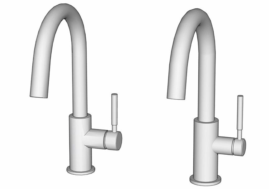
Figure 2.11 – These seem the same, but one has three times as much geometry as the other
In this example, the model on the right has a third of the number of edges and planes as the one on the left side. Despite this, they look the same! If we toggle on Hidden Geometry, you can really see the excess geometry:
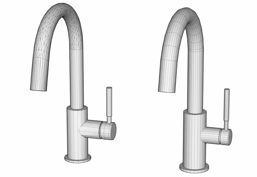
Figure 2.12 – Hidden Geometry reveals the excess geometry
In this example, we are looking at a few thousand extra edges or faces, but if this was continued through an entire model, it could add up to hundreds of thousands of extra pieces of geometry.
Model Statistics
To see what makes up your model, check out the Model Statistics tab in the Model Info window. It will allow you to see everything in your file and may help troubleshoot those that perform less satisfactorily.
One of the best parts of SketchUp can lead to the downfall of the indifferent modeler. SketchUp allows you to control how many edges are used in your curves and circles. Many new modelers assume, “The more, the better!” and crank circles up to the max (999 sides). The problem that this causes, of course, is unneeded geometry. How much geometry should you have in a model? That all depends on what the model is being used for.
Let’s take another look at the example from above. With something like a faucet, like many items you may model, it will probably be presented in one of three ways:
- It will be seen as a small detail in 2D output (construction drawing).
- It will sit in the background of the scene (design render or vignette).
- It will be the hero of a render (product image).
Each of these uses requires the faucet at a different level of detail. This means that there are actually three different answers to the question, “How much geometry is the right amount?”
Here are three models that could be used in each of the preceding examples, along with statistics for each model. Hidden Geometry has been toggled to visible to illustrate the differences between models. The first one would be perfect for dropping into something like a construction drawing or 2D construction detail:
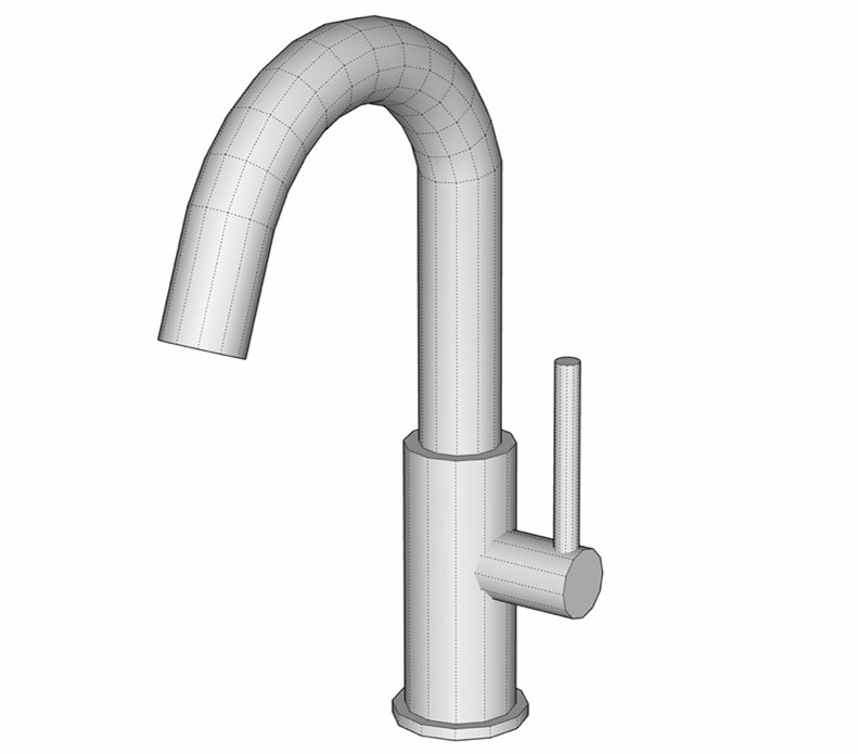
Figure 2.13 – Low-detail model perfect for a construction drawing (213 faces and 492 edges)
This next version of the faucet would be great for something like a design render showing the whole kitchen, or even a counter with a sink. There is enough detail here that it could be used in a render and stand up to fairly close scrutiny as part of a larger scene:
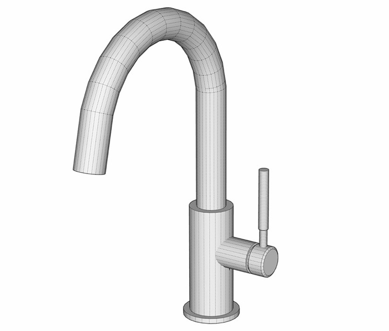
Figure 2.14 – Medium-detail model good for a general purpose (559 faces and 1,323 edges)
This model was purpose built for a product render. There is a lot of detail and a complex mesh creating the curve of the faucet that would not be noticed in most applications, making the extra geometry it brings to your model excessive and unneeded, unless the purpose of your model is to show off this faucet:
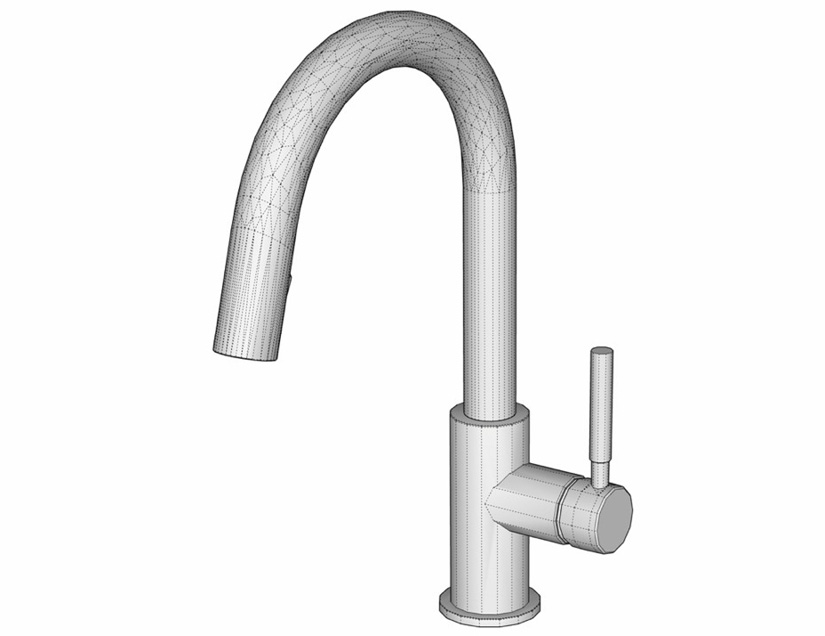
Figure 2.15 – High-detail model ideal for a hero render (2,190 faces and 3,831 edges)
Being conscious of how a piece of a model will be used and modeling appropriately for that specific use is something that sets a SketchUp ninja apart from the novices.
Optimizing materials
Much like geometry, image data imported into SketchUp can cause a file to become much larger than it really needs to be. Look at the two images in the model here:
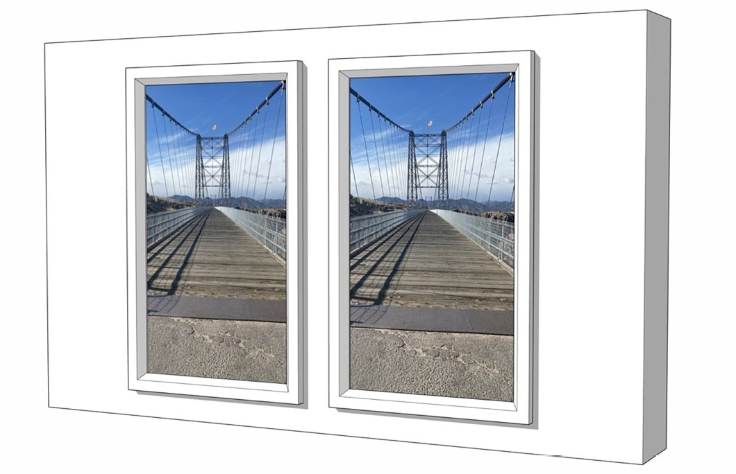
Figure 2.16 – (left) A 4k image that has a file size of 16.8 MB; (right) the same image in SketchUp but only 627 KB
To understand why these files are so different but look so similar in SketchUp, you need to understand how SketchUp uses imagery. When you import an image into SketchUp, it brings the entire image into the .skp file and saves it there. However, SketchUp downsamples the file to 1,024 pixels when it displays it in your model.
Maximum Texture Size
To have your imported images look as detailed as possible, make sure to turn on Use maximum texture size in the OpenGL tab of the SketchUp Preferences window.
This means that importing a huge image into SketchUp causes your model to be much larger without making it look any better. To keep your model optimized, you may want to consider downsizing images before importing them into the model. You do not have to import to exactly 1,024 pixels, as SketchUp will resize to the exact size as needed but resizing an image to approximately the size that will be used will help to keep your model compact.
Something else to note is how much performance was immediately impacted. The smaller image imported into SketchUp quickly and was easy to move around the model. When the larger image was imported, however, it jumped and lagged as it was moved around.
Another thing that creators of oversized model files do is import images of solid colors. Check out this example:
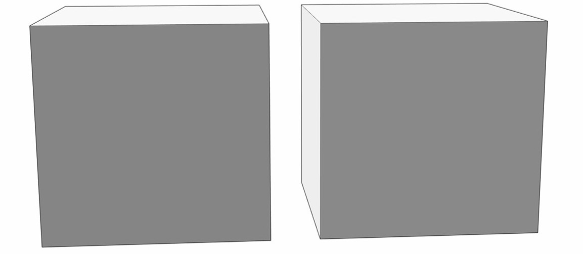
Figure 2.17 – (left) The cube has an imported image; (right) the cube has a color
In this example, the square on the left is an imported image adding 53 KB to the model, while the image on the right is a color added using a color from the color wheel in the Color window. This color adds virtually no additional data to the file. If this is done through your model, you can end up with a bloated, slow model with no improvement to the look of the model. On top of that, it takes time to import color swatch files into SketchUp while color samples are just a click away.
Extra Components, styles, and materials
Any time you import or create a Component, it is saved as a part of your model, even if you delete it from your screen. Any style you “try out” as you build your model is saved in your model. Every material you use, if it is picked from a library or imported, even if you don’t apply it to anything, is also saved.
This data is a part of your model even if you are not using it in your model. This extra data, especially unused Components, can lead to files that are several times larger than they need to be. The good news is you can clear up much of this unused data with a single command. That command is called Purge unused.
To run Purge unused, pull up the Preferences window and click on the Statistics tab.
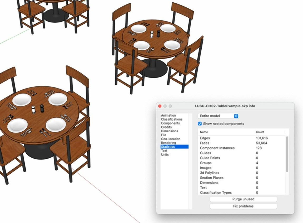
Figure 2.18 – The Statistics tab of the Model Info window (where Purge unused lives) displays all the information about your model
The Purge unused option is in the Statistics tab of the Model Info window. Clicking it will remove Components, styles, and materials that are saved in your model but not actively being used. In some cases, running this simple command can cut the size of a file in half!
A word of warning, though. If you have Components in your Component browser that you want to keep around, even though they are not currently in the model, or if you have colors that you plan to use in the future, but have not used yet, they will be lost when you run Purge unused. This command does not know what you plan to use in the future. It only knows what is on the screen, in the modeling area right now, and if it is not there, it is gone.
Purge unused is a command that everyone should run on their model at least once. If you ever plan to share your model, post it on 3D Warehouse, or just optimize the use of your computer’s storage, clicking this command will help dump the junk and leave you with a better SketchUp model.
Using visibility commands
While everything covered in this chapter so far will help you organize your models and make them easier to navigate and work with, there are situations where you will need to change something in your model as you work on it. You might want to temporarily hide one Object temporarily, or show what has been hidden in your model just for the duration of one modify command. These situations do not require a modification to your workflow but can be addressed using a few Edit and View commands.
Visibility while editing Objects
Any time you edit a Group or Component, you can temporarily hide everything else in the model with a single command. In the View menu is a sub-menu called Component Edit. In this sub-menu there are two toggles: Hide Rest of Model and Hide Similar Components. Clicking on one of these options will place a checkmark next to them. If they are checked, they will automatically activate anytime you edit an Object (yes, the name of the sub menu is Component Edit, but it works when editing Groups as well as Components).
Hiding geometry outside of the current context is a great way to simplify what you have on your screen and can make working in your model much easier. These toggles can make a big difference as far as what is on your screen at a given time:
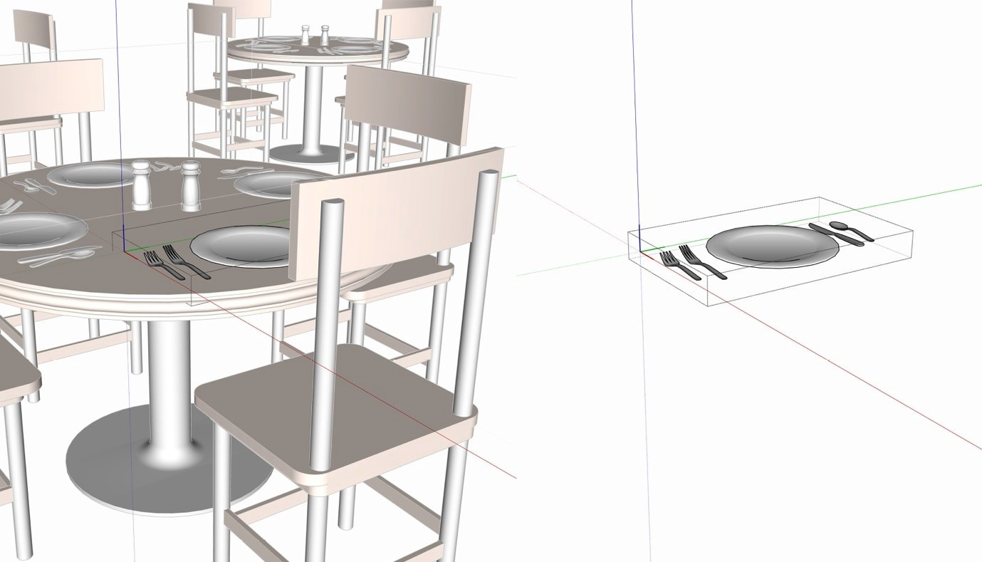
Figure 2.19 – Editing the Place Setting with Component Edit toggled off and on
Let’s take a look at an example. With both options toggled off (no checkmarks), do this:
- Open one of the Four Top Components by double-clicking on it.
- Now double-click on the Shaker Group.
Notice that everything that is outside of the Group is now a hazy, faded color, but still visible. This does a good job of calling attention to the contents of the Group but does not necessarily make the Group 100% accessible. If you orbit under the table, you will see that, even though the table is faded, it still prevents you from seeing the contents of the Group you are currently editing.
Controlling the Fade
You can control how much the items outside of the current Object are faded. In Model Info, under the Components tab, there are two sliders. These sliders allow you to control how faded the geometry is displayed. The two sliders allow you to control the fade Components that are copies of the current Component, or the entire rest of the model separately.
Let’s see how the model changes when we change those toggles.
- Choose Component Edit from the View menu then click on Hide Rest of Model.
Now, all you can see are the two shakers, because that is all that is visible inside the Group. The other Shaker Groups are still visible on your screen because you are editing a Group that is inside of a Component. Hide Rest of Model hides everything that is outside of the current Object but keeps it visible if it is a copy of an open Component. Let’s see how to hide that geometry.
- Click outside of the Shaker Group to get back to the Four Top Component.
- Choose Component Edit from the View menu and click on Hide Similar Components.
Now everything that is not inside the currently selected Component is hidden. These two commands are amazing tools to have as you work on models with lots of Objects.
Quick Toggles
Many expert modelers will assign shortcut keys to one or both commands making it easy to toggle them while in the middle of their modeling workflow. We will cover setting up custom shortcuts for these commands in Chapter 7, Creating Custom Shortcuts.
Hiding things from yourself
While tags are definitely the best way to control visibility, there are times where you may want to hide a single Object or piece of geometry. This is most easily done with the Hide command. Hide can be found under the Edit menu or, more easily, in the right-click context menu.
Let’s look at how to use, and more importantly how not to use, the Hide command:
- Click outside of any open Objects to close them.
- Right-click on one of the Four Top Components.
- Choose Hide from the context menu.
And the table is gone! Seems simple enough, right? Yes, making things disappear is easy. The real trick is in getting them back. Since you cannot see the hidden table, you cannot right-click it to choose Unhide from the context menu. Many a novice modeler has lost pieces of their model using the Hide command without understanding where hidden things go.
Before hiding something, you should know that hidden does not mean erased. Hidden items are in your model. Other geometry can and will interact with them. They still add to the geometry and data in your file. You cannot see hidden geometry or Objects, but they are still there.
So, how do you get hidden geometry back? There are two options. The first depends heavily on you not having hidden more than one item at a time.
- Open the Edit menu and click on Unhide.
- Choose Last from the sub-menu.
At this point, the hidden Four Top should be back. The Unhide command has the option of unhiding the last Object or all Objects (or just those selected, but we will get to that in a moment). These are not very granular controls, so you need to be very careful using the Hide command. Personally, I recommend never hiding more than one face or Object using this command and, even then, only leave it hidden long enough to complete a set of commands before unhiding it again.
It is also important to know that hiding is context sensitive. This means that you can hide an Object that is inside of another Object but cannot unhide it if you leave the context. That sounded a little confusing, so let’s do a quick hands-on example:
- Double-click to enter one of the Four Top Components.
- Right-click on any of the Place Setting Components and choose Hide from the context menu.
- Click outside of the Four Top Component to close it.
- Open the Edit menu, click Unhide then choose All from the sub-menu.
Nothing happened! Does this mean that the hidden Component is gone forever? How do you get it back? The Unhide All command is context sensitive meaning it will unhide all hidden Objects in the current context. Since no Objects are currently open, it is unhiding all hidden items that are not in a Group or Component.
- Double-click to enter the same Four Top Component.
- Open the Edit menu, click Unhide then choose All from the sub-menu.
Another option is to use the Unhide Last command. Unhide Last will unhide the last thing hidden, regardless of context. This is great for getting back something inside of a Group or Component. There is, however, a limitation to Unhide Last. If you run Unhide All, you will lose the ability to run Unhide Last, even if Unhide All did not unhide anything. This is another illustration of why you should be careful and sparing with the Hide command.
Seeing the invisible
Unhiding is great, but there has to be a way to see things when they are hidden, right? Of course there is – so let’s dive into that right now. First, let’s make a mess in our model then use the visibility toggle to allow us to clean things up:
- Right-click and use Hide to hide one of the Four Top Components.
- Double-click to enter another Four Top Component and hide the Shakers and a couple of Place Settings instances.
- Double-click to enter the Table Component.
- Select the face that creates the table’s top.
- Right-click and hide the face.
- Click outside of the Table Component to close it.
- Then click outside of the Four Top Component to close it.
At this point we have several things missing. And Unhide Last or Unhide All will only get us one piece back, at best. Fortunately, we have a simple tool to get it all back. In the View menu there are two toggles that we are going to use: Hidden Geometry and Hidden Objects. Let’s start with the second.
- Open the View menu and toggle on Hidden Objects.
As soon as you do this, all of the Groups and Components we hid are shown with dashed lines and a faint hatched fill. These hidden Objects can be interacted with the same as visible items, making it possible to modify, delete, or unhide any of them! Let’s get our hidden Objects back.
- Right-click on the hidden Four Top Component.
- Choose Unhide from the context menu.
The whole thing is back! Let’s try to get the rest back. Since the Shakers and Place Setting are inside of a Component, you cannot right-click and select Unhide (Unhide will not be in the context menu) until you open the Four Top Component.
- Double-click the Four Top Component with the hidden Objects inside.
- Right-click and unhide the hidden Objects.
That brings back all of our hidden Groups and Components! Our hidden table top, however, is still missing. Not only that, but toggling on Hidden Objects did not even show the face that we hid. This is because the top of the table was not an Object but a single face. To see our hidden face we need to toggle on Hidden Geometry.
- Open the View menu and toggle on Hidden Geometry.
There’s the missing table top, and so much more! Notice the dashed lines on the plate, the silverware, and the shakers. Hidden Geometry will not only toggle geometry that was hidden by an intentional Hide command, but also geometry that was hidden in order to smooth the geometry. Let’s take care of our table, then look at some of those hidden edges.
- Enter the table Component and unhide the hidden table face.
Whenever you run certain commands such as Soften/Smooth, or if Push/Pull or Follow Me are used to extrude a curve, you will have hidden geometry automatically created in your model. In Chapter 1, Reviewing the Basics, we talked about how surfaces are created by hiding the edges between faces. When a surface is selected the whole thing is highlighted. If Hidden Geometry is turned on, however, you can interact with any of the faces or hidden edges as if they were normal geometry.
- Open the Four Top Component, then the Place Setting Group, and then the Plate Component.
- Click on a face.
When hidden geometry is visible you can interact with the pieces between hidden edges. This means you do things that you cannot do with the full surface, such as use Push/Pull on a single face or paint a section of a smoothed surface. Let’s use these hidden faces to add detail to our plate.
- Use Shift and Select to select a ring around the edge of the plate. Your selection should look like this:
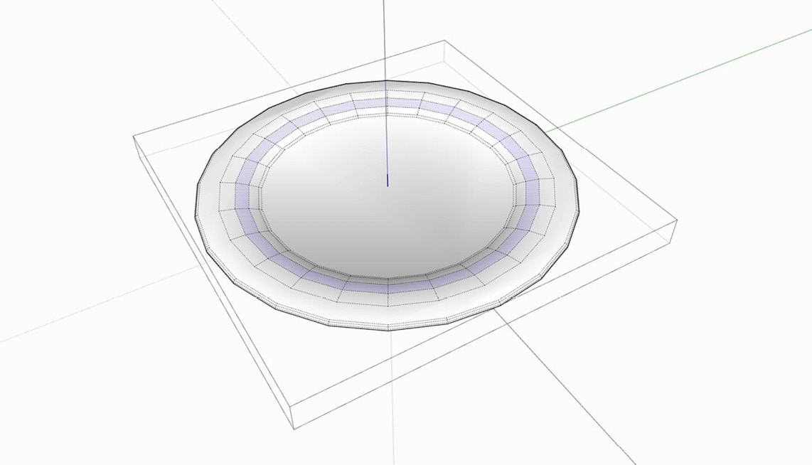
Figure 2.20 – Selected hidden geometry
- Now use the Paint Bucket tool to fill the selected faces with a blue color.
- Use Select to click outside of the Objects until you are completely out of all Components.
- Open the View menu and toggle off Hidden Objects.
- Open the View menu and toggle off Hidden Geometry.
More Toggles
Just like Component visibility, many users will set shortcuts for one or both visibility toggles. Custom shortcuts will be covered in Chapter 7, Creating Custom Shortcuts.
With that, you not only have all of your model back, but you have a smooth, seamless line painted around your plate:
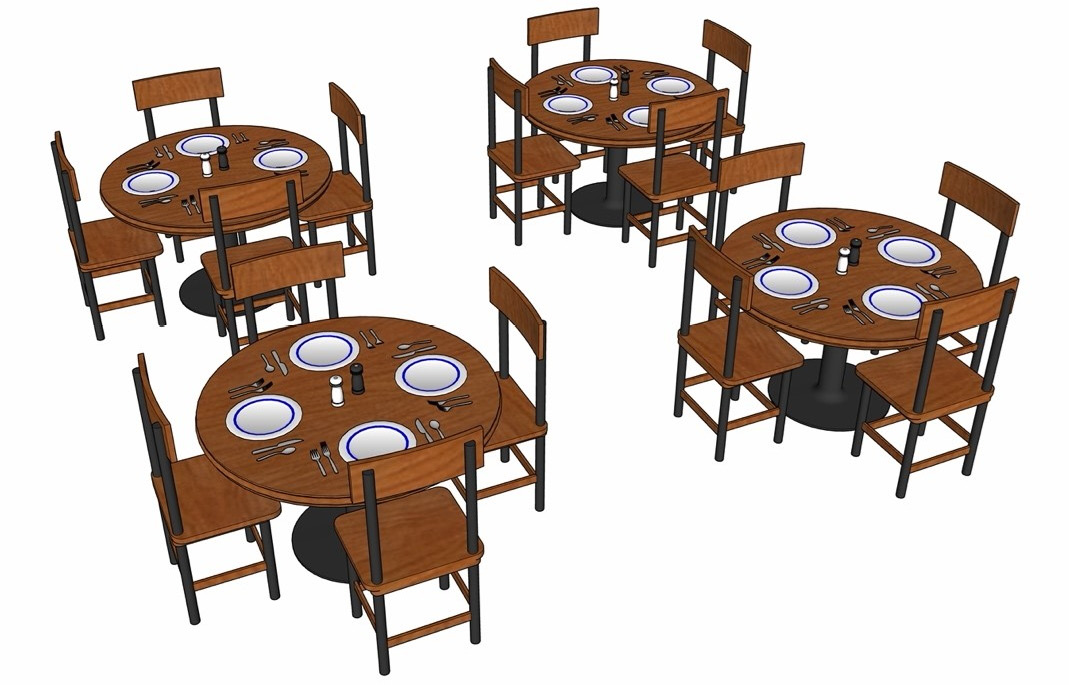
Figure 2.21 – Final model
Understanding how to use visibility commands is something that will not only make it easier to work with, but will also improve the performance of more complex models.
Summary
In this chapter, we started by diving into ways that you can customize your modeling workflow to make models that are more organized and performant. We saw how to use Groups, Components, and the Outliner to organize your model and learned when to purge the unneeded data that can cause model bloat. We also saw how to use scenes and visibility toggles to allow you to see exactly what you need while working on your model.
In Chapter 3, Modifying Native Commands, we will dive deep into native input and modification commands and how you can get more out of them than you thought possible using modifier keys.