4
Taking Inferencing to the Next Level
The inferencing system in SketchUp is one of the things that sets it apart from many other 3D modeling tools. When modeling in SketchUp, inferencing is always running and offering you options on where to click or how to draw in 3D space. A big difference between a SketchUp beginner and someone on track to becoming a SketchUp legend is their ability to use inferencing to draw exactly what they want.
In this chapter, we will cover three main topics:
- Inputting with inferencing
- Inferencing and tools
- Using inferencing with objects
Technical requirements
In this chapter, it is assumed that you have access to SketchUp Pro and the Taking SketchUp to the Next Level – Chapter 4.skp file:
Inputting with inferencing
Many new users can be caught off guard by inferencing when they first see it. It can be confusing, with the different color lines and dots showing up and the tool tips appearing and disappearing. But once you learn what each of the colors and symbols mean, using inferencing can mean accurate input from the start and less editing of geometry after it is drawn. There is a lot to inferencing! In this section, we will look at how to use inferencing to draw along the axes and find out what different colors and symbols mean with regard to drawing in SketchUp.
Axes colors
I remember being a little bit confused when I first started using SketchUp. At that point, I had been using many other 3D modeling programs, and they all had one thing in common – X, Y, and Z axes. SketchUp, on the other hand, never mentioned any axes by these names; instead, they just colored them. Whereas I was used to a Z axis, they had blue. X was called red and green replaced Y. While this felt a little off at first, in the long run, it was so much easier.
With the colored axes, I don’t have to remember what “up” is in 3D space. In fact, because I have access to the Axes tool, the axis that aligns with “up” can change at any point! The important point with this system is not the name or direction of each axis; it is the fact that each one has its own distinct color, and inferencing will reference and display those colors.
Customizing the Axes’ Colors
Throughout this section (and the rest of the book), I will refer to the colors of the axes as red, green, and blue. If you need to change any of those colors for any reason (color blindness, for example), you can make that change in the SketchUp Preferences window. The first tab, Accessibility, has controls that allow you to change the color displayed on your screen for each of the axes.
While drawing lines along the axes tends to be a basic function, let’s take a quick look at an example:
- Open the Taking SketchUp to the Next Level – Chapter 4.skp file and start up the Line command.
- Click just to the right of the origin. As you move your cursor around the screen, you will see a preview of the line you may end up drawing. As your cursor moves so that the line is parallel to any of the axes, the line will snap to parallel and change color. Clicking at this point will assure the creation of a line that is parallel to that axis.
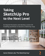
Let’s draw a square using only the Line tool and inferencing.
- Move your cursor until it snaps to the green axis, type 2m, and press Enter.
- Now, move your cursor to the right along the red axis, type 2m, and press Enter.
- Draw the third side by moving your cursor down the green axis, typing 2m, and pressing Enter.
- Close the bottom of the cube by clicking back to the beginning of the first line. By moving along the axes, then entering an exact length, you have created a perfect square in four steps:
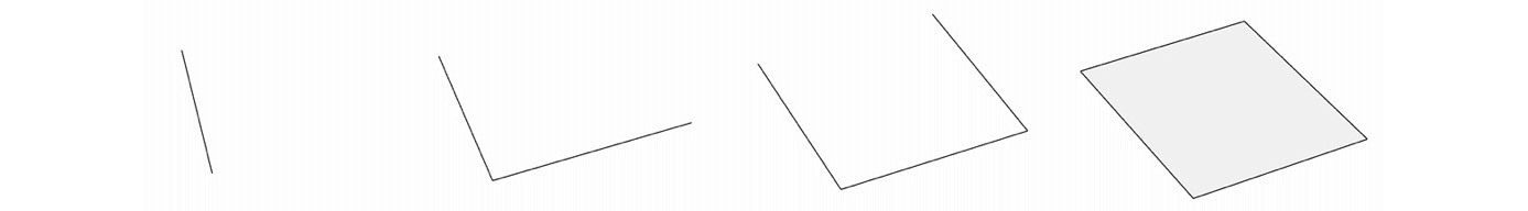
Figure 4.1 – All four steps of drawing a square using inferencing
By moving the mouse until it aligns with an axis and then typing a dimension, we are assured that the new line is exactly in line with the axis. What happens, however, when we cannot rely on the cursor to stay in line with the axis as we move the cursor through the model? This is when we must lock our inferences.
Locking axes’ inferences
There are two ways to lock to the red, green, or blue axes. The first way is to tap the arrow key that aligns with the axes:

Figure 4.2 – Three axes and their inference lock keys
While the blue axis is easy to remember, I used to struggle to remember whether I should tap the left or right arrow to align to the red axis. Then, I realized that “red” and “right” both started with R, and I can now remember that the right arrow key locks in the red axis!
Let’s turn this square into a cube by using the Line tool and locking the inference:
- Start a line at the back corner of the square and then tap the Up Arrow.
- Move your mouse upward, and then type 2m and press Enter.
- Tap the Right Arrow and move your cursor to the right, and then type 2m and press Enter.
- Click back down to the square on the ground to complete this side of the cube.
- Use the Line tool and axes locks to complete your cube.
With that, we have a simple hand-drawn cube.
Seeing the Colors
If you are doing a lot of work with geometry that should stay parallel to the main axes, you may want to turn on Color by Axis for your edges. In the Style window, under the Edit tab, you can choose the color for the edges. In the dropdown, there is an option called Color by Axis. Choosing this option will color code all edges with the axis to which they are parallel.
There are probably one or more of you out there thinking that you could have done this quicker using the Rectangle and Push/Pull tools, and that is true. However, there are times when it will pay off to try using modeling techniques that you don’t normally use in order to broaden your skills.
For example, I read the comments of a poster on our forum (https://forums.sketchup.com) who made some amazing scale train models. They were super-detailed and amazing to look at. After asking a few questions, the poster mentioned that he had never used the rectangle tool but drew everything with just the line tool. He had spent years refining his modeling process without even knowing that there was a single tool that could cut out 75% of his input time!
The point is this – whether it is in a book like this or just modeling for work or fun, do not be afraid of trying to use a new method or tool. You never know when going “outside your box” will show you a new way to model or teach you a new trick!
Leaving the axes
Knowing how to use the arrow keys to lock to an axis is great and something that you will likely use quite a bit. But being able to lock to edges that are not parallel to an axis is important as well! Let’s take a look at how to lock into a line that falls off-axis, using the Down Arrow key to lock to the magenta inference:
- Click on the MAGENTA INFERENCING scene in your practice file and bring up the Line command.
In this example, we will add to the rectangle (which is currently 1m x 2m) to make it a 2m square. Since the whole rectangle is at an angle, you will not be able to use the arrow keys to lock to an axis:
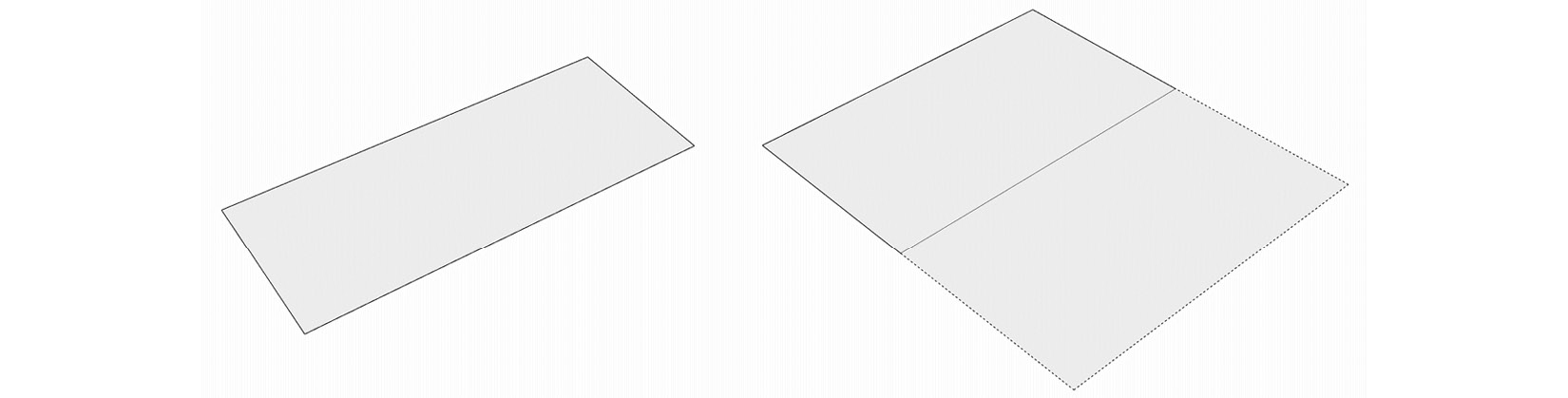
Figure 4.3 – The rectangle on the left needs to end up looking like the square on the right
- Click to the corner that is closest to you and move your cursor in the direction that you want to draw your first line.
As you move your mouse in line with the existing edge of the rectangle, it will lock and turn magenta. This is what we want to lock in. To do so, we need to let SketchUp know which edge we want to inference for the magenta lock.
- Move your cursor back along the line so that the edge you are drawing runs back up onto the short edge of the rectangle. Then, tap the Down Arrow key to lock to this inference.
Note that the line you are pulling and the entire side of the rectangle have turned magenta. You are now locked to that line, as shown here:
Image 4.4 – Magenta parallel reference
- Move your cursor away from the existing rectangle, type 1m, and press Enter.
The next line you need to draw is perpendicular to the one you just completed. You can do this using the exact same key but by pressing it twice.
- Move your cursor back over the line you just drew and tap the Down Arrow two times.
The first time you tap the Down Arrow, you are back in a parallel inference lock. The second time you tap Down Arrow, you change it to a perpendicular lock. You are now locked at 90 degrees to the inferenced line.
- Move your cursor to the right (the direction the long edge should run), type 2m, and then press Enter.
- Click back to the edge of the original rectangle to close the square.
Learning to use the magenta inference is a huge time saver if you ever model anything that is not perfectly aligned to the main axes.
The Shift Key
When drawing edges, as we have been in these examples, you can always hold down the Shift key to lock in the current inference. This is a nice option to have, but you lose it as soon as you release Shift. Using an arrow key will lock into an inference and keep you there until you finish drawing the edge or change to another inference.
Snap points
Of the things that I have always appreciated about using SketchUp is the way that the inferencing engine automatically finds and presents me with potentially useful snap points. When I first used SketchUp, I found out that the other drawing programs I had used required you to press a key to use a snap point or toggle the visibility of all snap points if I wanted to use them. Not SketchUp, though! SketchUp sees what you are doing and offers you the snap point that it thinks you might want to use.
This is an important part of modeling in SketchUp and makes it imperative that you understand the different point types you see on the screen. There are four different point types that you will see on the screen, and each one can be displayed in different colors, indicating different options:

Figure 4.5 – Snap points’ shapes and types
These different points may show up as you are modeling in different colors. I know it can sometimes be hard to see them, but each snap point has different potential colors and will change, based on what it is inferencing. Here is a list of all point shapes and the colors they may show up in:
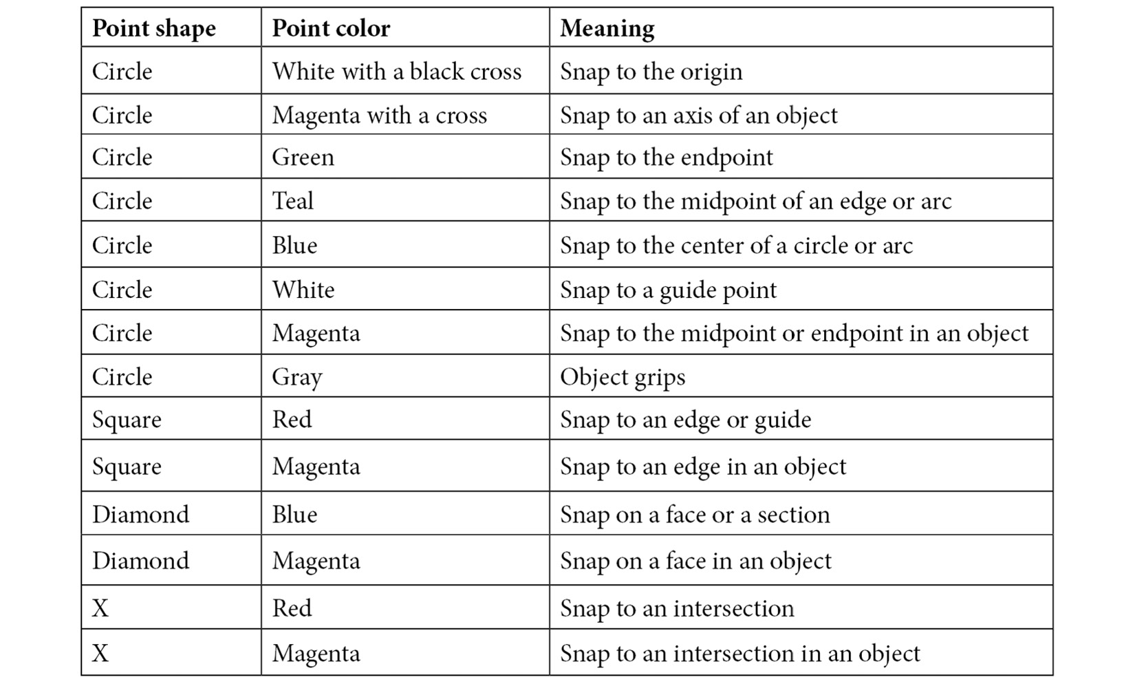
Figure 4.6 – Points, colors, and snap types
Understanding that these different points will show up as you work in your model is essential for speeding up input. If you do not pay attention to what you are snapping to, it is very hard to be assured that you are actually drawing what you want, in 3D space.
Projected inferencing
An important inference that I want to look at is projected inferencing. This is its own inference that will show up as you model and is a big time saver. Projected inferencing looks at the points that are in a model and allows you to snap where the edge you are drawing to would intersect with another edge or point if the two of them met. Projected inferences show up as dotted lines along an axis, from the inferenced point to your cursor, and are a great way to align edges to existing geometry or find the center of a rectangle! Let’s give that a try right now:
- Click on the PROJECTED INFERENCING scene in your practice file and pull up the Line command.
- Hover over the left edge of the rectangle until the midpoint snap shows up (a teal circle).
- Without clicking, slide your cursor toward the center of the rectangle. See the dotted red line that is following your cursor from the inferenced point? That is a projected inference. If you click while that inference is visible, the point you click on is assured to be in line with the midpoint of the left edge of the rectangle:
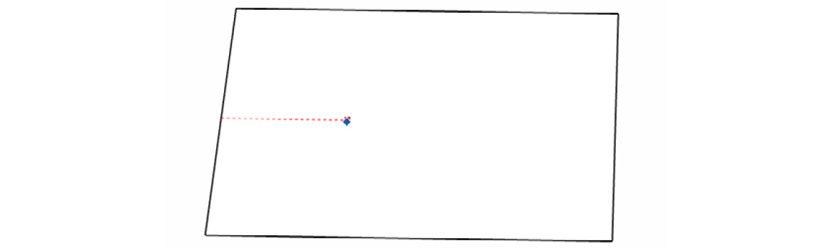
Figure 4.7 – The dotted red line shows a projected inference from the midpoint of the edge
- Now, move your cursor up and find the midpoint of the top edge of the rectangle.
- Once again, without clicking, move your cursor down toward the middle of the rectangle.
This time, you have a green dotted line following the cursor, indicating that you are aligned vertically with the center of the top edge of the rectangle.
- Continue to move your cursor down toward the center of the rectangle. When you get to the center, you should see a red dotted line from the midpoint of the left side and a green dotted line from the midpoint of the top side, meeting in the very center of the rectangle:
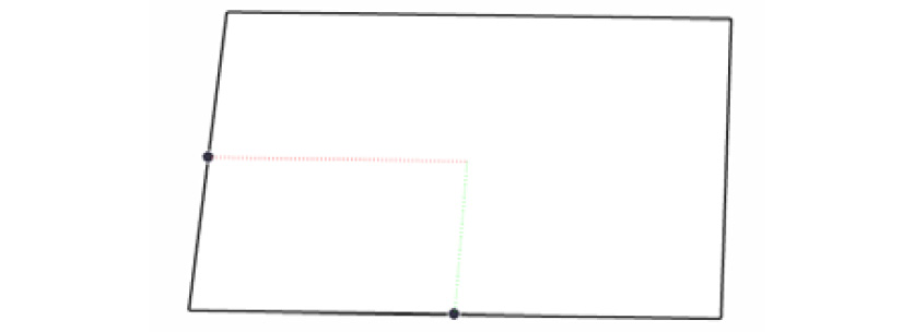
Figure 4.8 – Red and green projected inferences meet at the center of the rectangle
This inferenced point is the very center of the rectangle. This, of course, will only work if the sides of the rectangle are aligned with the axes, since the projections align to the red and green axes, but this is still a very helpful tool for aligning geometry as you draw.
Hover and Wait
If you are moving your cursor away from a point and are not seeing a dotted line, you may need to hover just half a second longer. SketchUp identifies points that you want to use as reference when you keep the cursor over them for a second or so.
Inferencing planes
So far, all the examples we have looked at have been about locking to edge inferences. Inferencing can be used to lock the planes as well! Let’s take a look at drawing some rectangles by locking onto specific planes by finishing off a cube in your practice model:
- Go to the PLANE INFERENCING scene in your practice model and start up the Rectangle command.
- Tap the Left Arrow key to lock to the green plane. Watch your cursor as you perform plane locking. You will see that the rectangle cursor will change orientation and color as you lock to specific planes. In this case, the green plane aligns with the rectangle we want to draw to create the missing front face of the cube.
- Click on the front corner of the square on the ground and move your mouse up and to the left.
Note that no matter where you move your cursor, you are locked into that green plane!
- Click on the square at the upper left to create the front side of the cube.
- Now, tap the Right Arrow key to lock to the red axis and add a rectangle to the right side of the cube.
- Finally, tap the Up Arrow and draw one last rectangle to form the top of the cube. That explains up, left, and right, but what about the down arrow key? Just as with inferencing for line drawing, plane inference uses the Down Arrow key to lock to any plane that you are hovering over, to create a magenta inference. Let’s use the rotated cube on the right to see some magenta inferences.
- Hover the rectangle cursor over one of the sides of the rotated cube and tap the Down Arrow. As soon as you tap the key, the rectangle cursor snaps to the plane of the face you were hovering over and turns magenta. Let’s draw a rectangle on this face of the cube.
- Click to set a start point, and then move your cursor to drag out a rectangle. Note that the rectangle stays in the plane of the face, but it does not align with the shape of the side of the cube. This is an important fact to remember about magenta inferencing. It will draw in the inferenced plane, but the actual direction of the rectangle being drawn will align, as best as it can, with the axis of the model or current context.
- Click again to finish the rectangle, move your cursor to a different side of the cube, and tap the Down Arrow again.
- Move your cursor off the cube. Note that you can move your cursor completely away from the inferenced geometry but retain the orientation of the plane. This is a key use of plane inferencing. With this process, you can duplicate things such as roof slopes or landscape gradients by inferencing one example and reproducing them elsewhere.
No Perpendicular Planes
Unlike line inferences, the Down Arrow will not jump to a perpendicular plane if you tap it twice. Tapping the Down Arrow key twice will simply release the inference.
One of the advantages of using the magenta inference is that SketchUp will remember what the last plane referenced was.
- With your cursor in open modeling space (not over either cube), tap the Down Arrow again. Note that the inference has been released.
- Now, while still in open modeling space, tap the Down Arrow, again. The magenta inference is back and still aligned to the side of the cube! As long as you don’t tap the Down Arrow while hovering over another face, it will remember the last plane inferenced.
Shift Works on Planes, Too
As with line inferences, plane inferences can be held by holding down the Shift key. The same limitation is here, too, though. Should you release the Shift key at any point, you will release the inference.
That is a lot of inferencing! Note that we only really looked at two commands (Line and Rectangle), but these inferencing practices work the same for all of the drawing commands. Understanding how to use axis locking, snap points, and plane inferencing are key to speeding up your 3D modeling process and something that all great SketchUp modelers do instinctually.
Now, let’s take what we have learned about inferencing for input and see how it applies to modifying geometry with the tools!
Inferencing and tools
The good news when it comes to mastering inferencing while using tools is that everything covered in the previous section (colors, arrow keys, and snap points) applies to tool usage, as well as drawing. Of course, they are used in different ways, which is what we will dive into right now.
Moving and inferencing
Let’s start with a basic tool such as Move. Let’s see how Move works with the different inferences and snap points when moving an edge and a face:
- Get to the TOOL INFERENCING scene in your practice file and bring up the Select command.
Note that this scene has the Color by Axis setting turned on for edges. Any edge that is parallel to an axis is shown with that axis’ color.
- Use Select to highlight the vertical line on the right and then bring up the Move command.
We are going to use some snap points to move the selected line into the center of the circle at the back.
- Hover your cursor over the bottom of the vertical line. Click when you see the endpoint.
- Now, move your cursor and hover over the edge of the circle. When the center point of the circle shows up, move the line so that the bottom snaps to the center point.
Even though you cannot see the center of a circle, SketchUp knows where it is and presents it to you as a viable snap point when the time is right, as shown here:
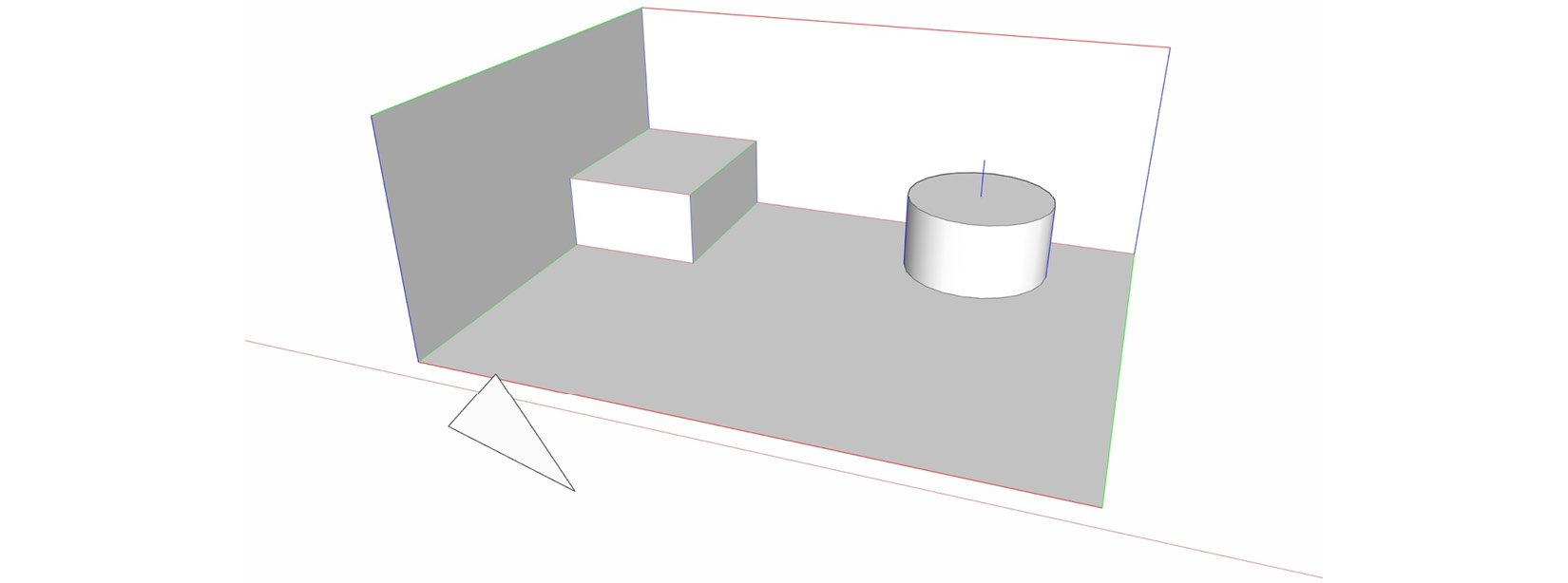
Figure 4.9 – The vertical line exactly lined up with the center of the circle
Finding the Center Point
To get the center point of an arc or circle to show up, you need to hover over the edge for a second or so. Once you do, the center point will show up with a dotted line connecting it to your cursor.
Now, let’s use some projected inferences and Rotate to line up the triangle with the box in the corner.
- Use Select to double-click on the triangle, and then bring up the Rotate tool.
- Tap the Up Arrow key to lock rotation to the blue axis.
- Click on the left endpoint of the triangle’s base and then on the right.
- Now, tap the Right Arrow key to force the triangle to align to the red axis and click again.
Since the base of the triangle and the top edge of the box in the corner are both red, we are assured that they are parallel:
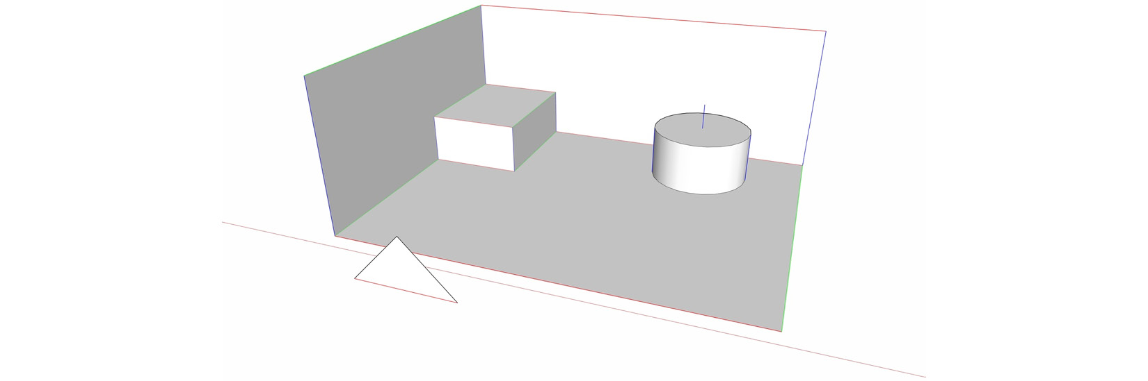
Figure 4.10 – The base of the triangle is now aligned with the box at the back
Now let’s line up the triangle with that box. To practice using inferencing, we will do this in three moves.
- With the triangle still selected, bring up the Move tool, choose the right end of the triangle, and tap the Right Arrow key.
- Now, to line up the triangle with the box along the red axis, click anywhere on the right side of the box. You can hover over the right face of the box, on an edge that defines that face, or any of the endpoints or midpoints along those lines.
Since we moved along the red axis to the green axis of the box, we are assured that everything lines up:
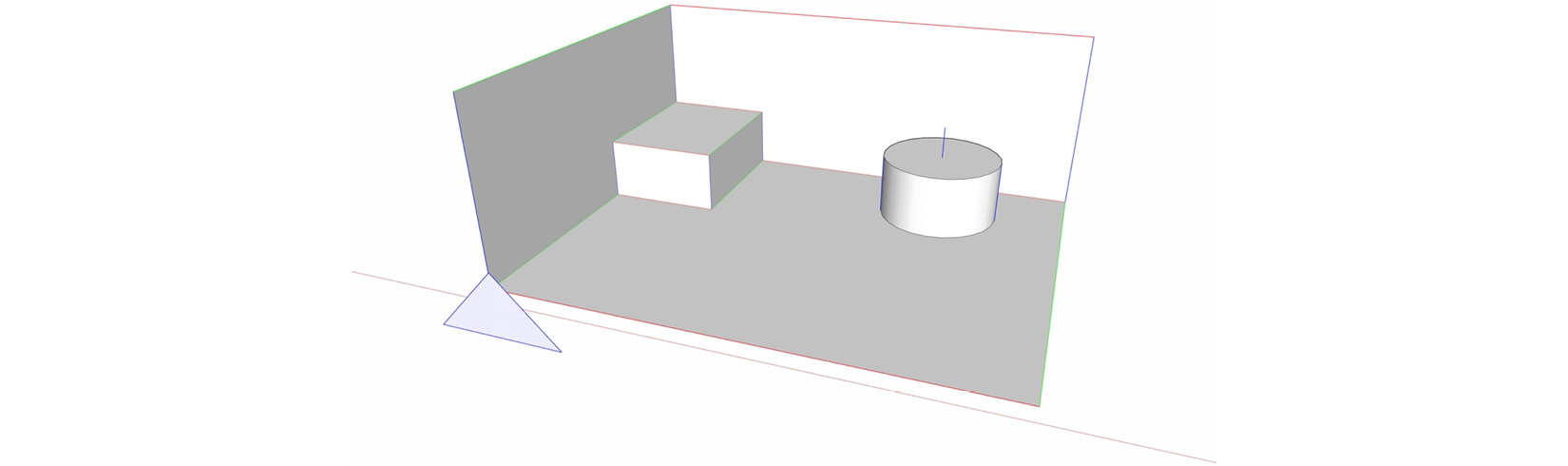
Figure 4.11 – The edges of the triangle and the box are aligned along the red axis
Now that the triangle is lined up with the face of the box, let’s move it vertically so that the base of the triangle is at the same height as the top of the box. We will do this without using any snap points on the triangle.
- With the triangle still selected and while still in the Move tool, click any point or edge along the bottom of the box, and then tap the Up Arrow key.
- Now, move your cursor up and click on any edge, point, or face of the top of the box.
Since we have constrained our movement to the blue axis, it does not matter where we click, as long as the distance, vertically, between the first and second click is the same as the distance between the top and bottom of the box. This is sometimes referred to as a relative move, since you are using points that are at a relative distance from each other rather than picking points on the item being moved.
While we cannot go into every tool and how it uses inferencing, remember that inferencing is always happening and always available to you as you model. Almost every command allows you to lock to an axis or magenta inference at some point during its use, using either the Arrow keys or the Shift key. Knowing how inferencing applies to edges and faces is important, but if you are following the practices we set in earlier chapters, you will likely be using inferencing to modify groups and components. Let’s spend a little bit of time covering how inferencing can be used when modifying objects and how it differs from moving loose geometry.
Right now, your model should look like this:
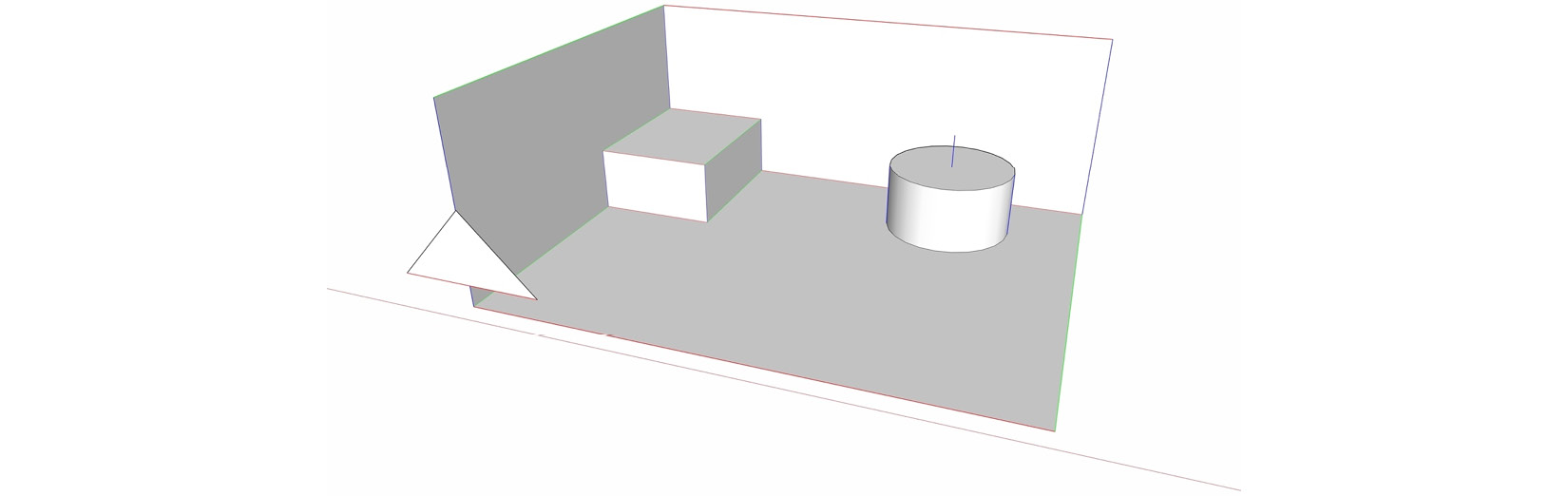
Figure 4.12 – The triangle is one step closer to being completely aligned with the box
- Now, use the Move tool to select the triangle by the midpoint of the baseline and place it on the midpoint of the front of the box.
The triangle is now perfectly aligned with the box:
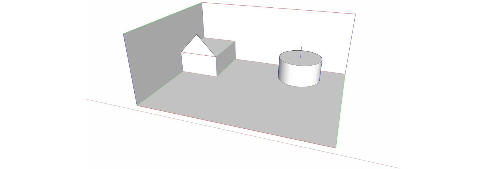
Figure 4.13 – The triangle is perfectly aligned
This is a simple example that shows the power of inferencing. If you think of geometry as existing in red, green, and blue planes, it is easy to modify it using inference locking and snap points. I know that we could have moved that triangle in one move, but I really wanted to do multiple steps to illustrate how to use axis locking to make it easier to select points while moving.
Using inferencing with objects
Whether you are modifying an object or selecting raw geometry, inferencing works the same. Picking points to use when modifying objects is, however, quite a bit different.
Since objects are considered single items rather than a collection of pieces, many tools do not work on objects. However, the tools that can be used on objects work differently, treating an object as a whole item. This gives you some capabilities that make it easier to move, rotate, or align objects that you don’t have when moving just geometry. To see the options for modifying objects, let’s hop back into the practice model:
- Go to the OBJECT INFERENCING scene and bring up the Move command.
- Hover your mouse over the cube. Note that as soon as the cursor moves over the cube, gray circles show up for all of the corners. Since the geometry of a cube completely fills the container, it may appear that the corner points are related to the geometry inside the group. Let’s see how these points, referred to as grips, work with different geometry.
- Move your cursor to the right and hover over the cylinder. Note that the grips are on the corners of the container and not the geometry. This is one of the big differences when it comes to moving an object. You can use any corner of a container as a handle to move and arrange groups or components. Let’s move the cylinder so that it is right against the cube.
- Pick the bottom-left corner of the cylinder, and then move that point to the lower-right corner of the cube. With that, the two containers (which happen to be the same size) are perfectly aligned. So, that works great when you can see the points, but what about the points at the back? Let’s say that we want to get the cube placed in the back corner. We need the lower-left back corner to fit in the far corner of the container behind it.
- While still in the Move command, with nothing selected (tap the Esc key to deselect any selected groups), hover over the cube.
Note the grip floating on the front face of the cube. That is actually a snap point for the back corner of the container (the corner you cannot see from this view).
- Hover over and click on that grip. As soon as you hover over that grip, everything in the container becomes transparent, allowing you to see the front and back sides of the geometry as well as everything behind the group!
- Move the back corner of the cube so that it aligns with the back corner of the container behind it and click to place it. This is another advantage of moving objects over raw geometry. Since SketchUp knows what is in the object, it can selectively make it transparent, allowing you to see through to the back side. This is great for aligning things such as furniture in rooms or placing sheathing on wall framing, where things align to a corner, but what if we want to use a point other than a corner of a selected object? Let’s align the middle of the cylinder with the middle of the back wall.
- While still in the Move tool, with nothing selected, move your cursor over the cylinder and tap the Alt/Command key. Note that the modifier listed in the status bar changes from Toggle Autofold to Cycle Through Grip Types when you hover over an object. Tapping the modifier key once will toggle you through four different snap options for object grips:
- Corners of a container (8 points)
- Midpoints of container edges (12 points)
- The center of the sides of a container (6 points)
- The center of a container (1 point)
Here is a quick diagram showing all of the possible snap options for a cube:
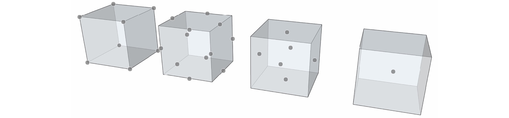
Figure 4.14 – Each of the grip sets, as they appear on a group or component
Note that toggling through this list will change the grips for all objects in the model, not just the object currently being interacted with.
- Use the midpoint on the bottom back edge to align the cylinder with the center of the wall behind it.
- Tap the modifier key a few more times to cycle back to corner grips, and place the sphere so that its back fits into the corner of the container behind it. With that, you should have all three objects nestled up tight into the geometry behind them:
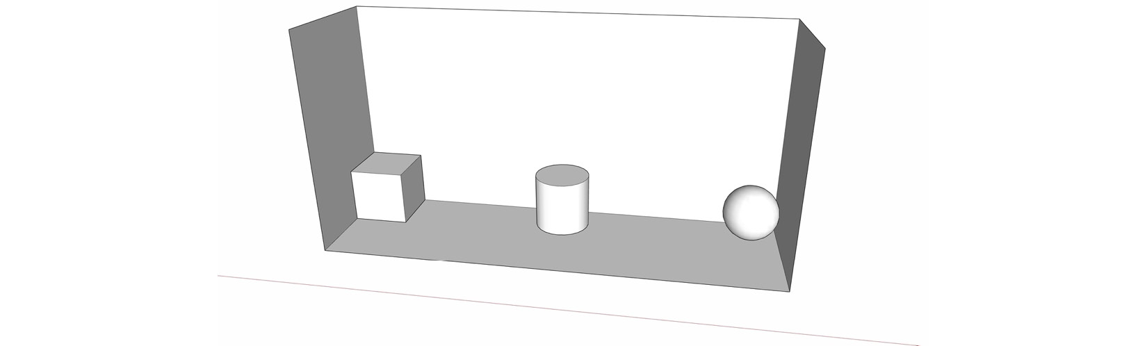
Figure 4.15 – The box, cylinder, and sphere snapped to the geometry behind
You can see how using grips on containers can be great for aligning items. Let’s do one more example to see how we can use interior grips to align geometry that you cannot see:
- Click on the GRIP STAMPING command, and if you are not already in it, choose the Move tool.
- Hover over the sphere and cycle through grips until you get the center grip.
- Choose the center grip and place the sphere at the end of the curved line:
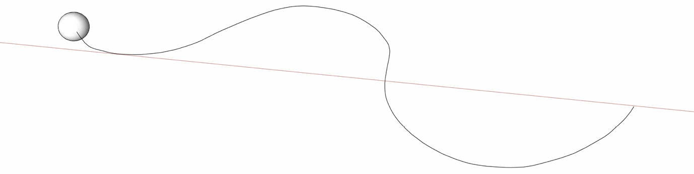
Figure 4.16 – One sphere on the path
- Now, tap the Control/Option key twice to toggle to stamp mode.
- Now, click along the line several times, placing a copy of the sphere on the line with each click:
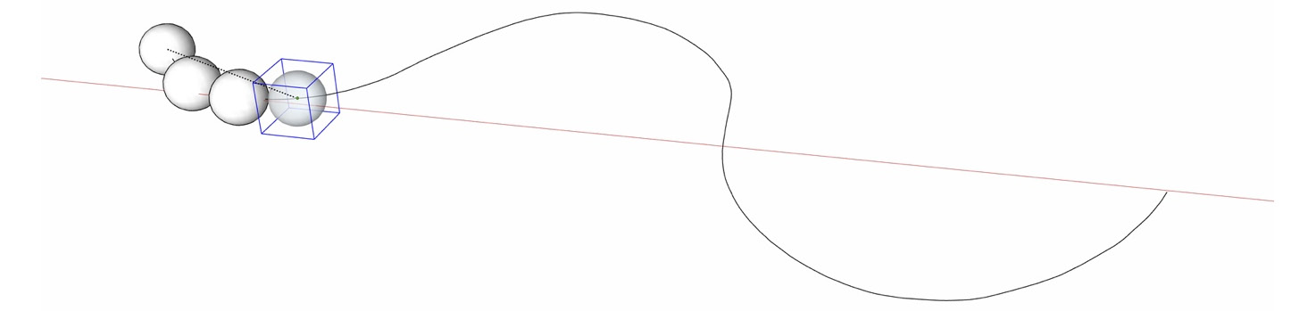
Figure 4.17 – Each click adds a new copy of the sphere to the string
- Continue clicking along the path until you have covered the path with spheres.
Knowing how to use grips to move and arrange objects is an important piece of leveling up your SketchUp skills. You can always use the geometry inside the group as grips as well, but being able to arrange objects using the corners or sides of the bounding box helps for quick and easy alignment of groups and components.
Summary
Inferencing is something that you start using the second you hop into SketchUp. Everyone uses it, but only skilled users take advantage of everything it can do. To truly take advantage of inferencing, you need to understand not just axis and color inferences but also parallel and perpendicular inferences, which we discussed in this chapter. We also learned about snap points and how to use grips when moving objects.
In Chapter 5, Creating Beautiful Custom Materials, we will be looking at the process of importing imagery and creating custom materials for use with the Paint Bucket tool.