CHAPTER 5
WORKING WITH BLENDS, FILTERS, AND 3D TRANSFORMATIONS
Now that we have given you a tour of the kitchen and its basic tools, we need to start adding some hot sauce.
In previous chapters you learned about the basic tools for creating graphics and colors. Here you will get familiar with the basics of spicing things up a bit more using blends, filters, and 3D tools. So in this chapter we will show you the following:
- Blends
- Filters
- 3D transformations
Blends
Blend modes let you create composite images or images with varying transparency or color interaction of two or more overlapping objects. Blending allows you to create unique effects by blending the colors in overlapping shapes, as well as adding a control to the transparency of objects and images. You can use Flash blend modes to create highlights or shadows that let details from an underlying image show through, or to colorize a grayscale image.
A blend mode contains these elements:
- Blend color: The color applied in the blend mode
- Opacity: The degree of transparency applied in the blend mode
- Base color: The color of pixels underneath the blend color
- Result color: The result of the blend's effect in the blend
Because blend modes depend on both the underlying "base" color and the color of the object to which you're applying the blend, you'll need to experiment with different colors to see what the result will be. Try the different blend modes to achieve the effect you want. Some samples follow.
Flash provides the following blend modes:
- Normal: Applies color normally, with no interaction with the base colors.
- Layer: Blends colors normally but sets the blend object at 100 percent opacity prior to blending. This prevents internal movie clips of the blend object from bleeding through one another.
- Darken: Replaces only the areas that are lighter than the blend color. Areas darker than the blend color don't change.
- Multiply: Multiplies the base color by the blend color, resulting in darker colors.
- Lighten: Replaces only pixels that are darker than the blend color. Areas lighter than the blend color don't change (opposite of darken mode).
- Screen: Multiplies the inverse of the blend color by the base color, resulting in a bleaching effect, often similar to lighten mode.
- Overlay: Multiplies or screens the colors, depending on the base colors.
- Hard light: Multiplies or screens the colors, depending on the blend mode color. The effect is similar to shining a spotlight on the object.
- Difference: Subtracts either the blend color from the base color or the base color from the blend color, depending on which has the greater brightness value. The effect is similar to a color negative.
- Invert: Inverts the base color.
- Alpha: Applies an alpha mask.
- Erase: Removes all base color pixels, including those in the background image.
Applying a blend mode
You use the Property inspector to apply blend modes to selected movie clips or shapes.
To apply a blend mode to a movie clip, follow these steps:
- Select the movie clip instance (on the stage) to which you want to apply a blend mode.
- Adjust the color and transparency of the desired movie clip instance using the Color pop-up menu in the
Property inspector. - Select a blend mode from the
Blendpop-up menu in theProperty inspector. The blend mode is applied to the selected movie clip instance. - Verify that the blend mode you've selected is appropriate to the effect you're trying to achieve.
Figures 5-1 through 5-5 show the results of applying various blend modes to a movie clip.
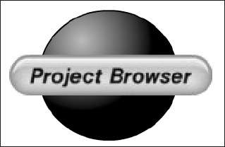
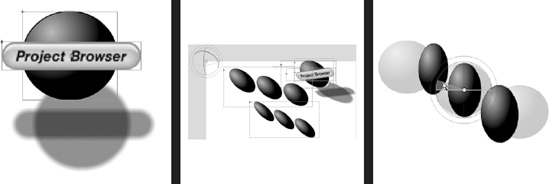
Figure 5-1. Normal blend mode produces no effect.
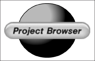
Figure 5-2. With hard light blending mode, the shadows and light source become sharper.
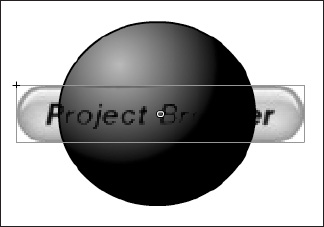
Figure 5-3. With darken blend mode, the lighter areas of overlap are replaced.
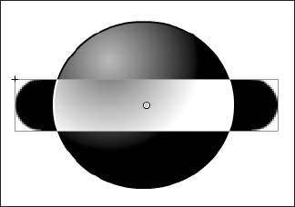
Figure 5-4. With invert blend mode, the base color is inverted in the overlap areas.
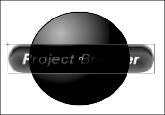
Figure 5-5. With subtract blend mode, the base color is subtracted from overlapped areas.
You will likely find you need to try varying both the color and transparency settings of the movie clip and then try applying different blend modes to achieve the effect you want. For information on adjusting the color of a movie clip, go to http://help.adobe.com/en_US/Flash/10.0_UsingFlash. Select Using Flash and in the left-hand pane, expand Using symbols, instances, and library assets, expand Working with symbol instances, and select the link Change the color and transparency of an instance.
Working with filters
Filters let you add visual effects such as drop shadows, blurs, glows, and bevels to text, buttons, and movie clips. You may apply these filters using motion tweens that are unique to Flash and with which you can animate the filters. For example, if you create a ball (or sphere) with a drop shadow, you can simulate the look of the light source moving from one side of the object to another by changing the position of the drop shadow from its beginning and ending frames in the timeline.
After you apply a filter, rearrange the order of filters or change filter options at any time to experiment with combined effects. You can disable filters or enable or delete them in the Property inspector. When you remove a filter, the object returns to its previous state. You can view the filters applied to an object by selecting it, automatically updating the filters list in the Property inspector for the selected object.
Applying filters
You can apply filters to selected objects using the Property inspector. Each time you add a new filter to an object, it is added to the list of applied filters for that object in the Property inspector. You can remove filters that have been previously applied, as well as apply multiple filters to an object. Applying different filters affects the appearance of a movie clip instance (see Figure 5-6).
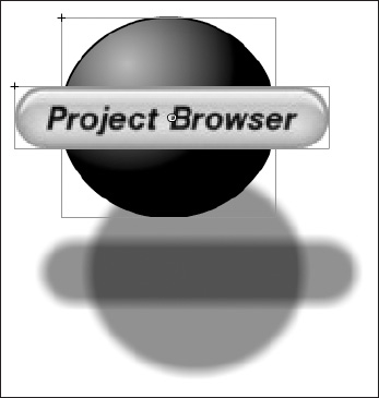
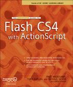
Figure 5-6. A drop shadow applied to multiple objects
For information on how using filters can affect the performance of your SWF files, see the following sections of Flash Online Help: "Filters and Blends" (located at http://help.adobe.com/en_US/Flash/10.0_Welcome under Using Flash ![]()
Using Flash CS4 Professional ![]()
Filters and Blends) and "Filtering Display Objects" (which you'll find at http://help.adobe.com/en_US/ActionScript/3.0_ProgrammingAS3 located to the left).
You can apply filters only to text, button, and movie clip objects. To apply a filter, follow these steps:
- On the stage, select a movie clip, button, or text object to which you want to apply a filter.
- Select the
Filterstab in theProperty inspector. - Click the
Add Filter(+) button in the lower-left corner and select a filter from theFilterspop-up menu (see Figure 5-7). The filter you select is applied to the object, and the controls for the filter settings appear in theProperty inspector(see Figure 5-8).
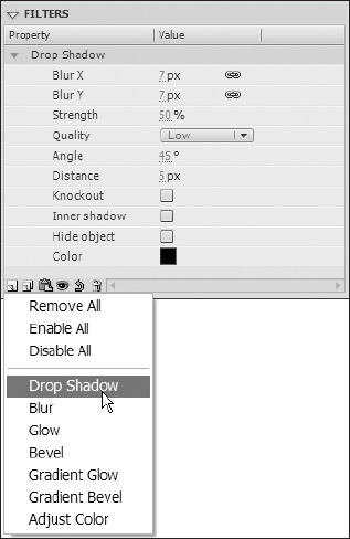
Figure 5-7. Adding a filter to the filter tab in the property inspector
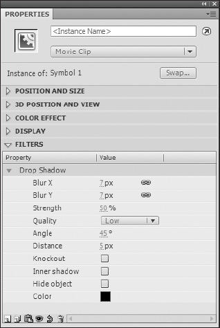
Figure 5-8. Setting your filter properties
Vary the filter settings until you get the look you want. For details about the settings available for each filter, see the following sections in Flash Online Help (http://help.adobe.com/en_US/Flash/10.0_Welcome), all of which can be accessed by first selecting Using Flash, expanding the Special effects node, and then expanding the About filters node:
Apply a Drop ShadowApply a BlurApply a GlowApply a BevelApply a Gradient GlowApply a Gradient BevelApply the Adjust Color Filter
To remove a filter, follow these steps:
- Select the movie clip, button, or text object that you want to remove a filter from.
- Select the
Filtertab in theProperty inspector. - Select the filter you want to remove in the list of applied filters.
- Click the
Remove Filter(–) button to remove the filter.
You can create a filter settings library that allows you to easily apply the same filter or sets of filters to an object. Flash stores the filter presets you create in the Property inspector on the Filters tab in the Filters ![]()
Presets menu. You can delete or rename any presets as desired.
The filter configuration file stored in your Flash configuration folder can be used to share libraries of preset filters with other developers.
For more information, go to http://livedocs.adobe.com/flash/10.0/UsingFlash/. Select Using Flash, expand Special effects, expand About filters, and click the link Creating preset filter libraries.
To enable or disable a filter applied to an object, click the enable or disable icon next to the filter name in the filter list in the Property inspector. Alt-click the enable icon in the filter list to toggle the enable state of the other filters in the list. If you Alt-click the disable icon, the selected filter is enabled and all other filters in the list are disabled.
To enable or disable all filters applied to an object, click the Add Filter (+) button in the Property inspector and then select Enable All or Disable All from the pop-up menu. You can Ctrl-click (Cmd-click) the enable or disable icon in the filter list to enable or disable all the filters in the list.
At this point, you may want to try applying a basic filter effect yourself. There are many examples in the Flash documentation, as indicated earlier. However, an easy example to start with is applying a drop shadow, so try it out by using the following steps:
- Select the movie clip, button, or text object that you want to apply a filter preset to.
- Select the
Filtertab in theProperty inspector. - Click the
Add Filter(+) button and selectPresetsfrom theFilterspop-up menu.
Select the filter preset you want to apply from the list of available presets at the bottom of the Preset menu. When you apply a filter preset to an object, Flash replaces any filters currently applied to the selected object(s) with the filter(s) used in the preset.
Creating a skewed drop shadow
To create a more realistic look, use the drop shadow filter's Hide object option when skewing the shadow of an object (see Figure 5-9). To achieve this effect, you need to create a duplicate movie clip, button, or text object, apply a drop shadow to the duplicate, and use the Free Transform tool to skew the duplicate object's shadow. Next, hide the original object with the skewed shadow and remove the drop shadow from the other copy.

Figure 5-9. Skewing the drop shadow filter to create a more realistic shadow
The effect is the original object has a shadow that is skewed to one side as if the light source casting the shadow were offset.
Introducing 3D transformations
Flash CS4 allows you to create 3D effects by moving and rotating movie clips in 3D space with a z axis in the properties of each movie clip instance. You add 3D perspective effects to movie clip instances by moving or rotating them along their z axis using the 3D Translation and 3D Rotation tools. In CS4, moving an object in 3D space is called a translation and rotating an object in 3D space is called a transformation. Once you have applied either of these effects to a movie clip, you get the z axis that makes it a 3D movie clip.
When you move an object along its z axis with the 3D Translation tool or the Property inspector, that object will appear nearer or further away from the viewer. When you rotate the movie clip around its z axis with the 3D Rotation tool, you give the impression of an object that is at an angle to the viewer. Through using these tools, you get the impression that the objects they are applied to are in 3D space, which is made even more apparent with movement.
You can use the 3D Translation and the 3D Rotation tools to manipulate objects on the entire stage (global) or movie clip (local) 3D space. For example, if you have a movie clip containing three nested movie clips as shown in Figure 5-9, local 3D transforms of the nested movie clips are relative to the drawing area inside the parent movie clip. The default mode of the 3D Translation and 3D Rotation tools is global. To use them in local mode, click the Global toggle button in the Options section of the Tools panel.
Vanishing point
The vanishing point property (see Figure 5-10) of an FLA file controls the orientation of the z axis of 3D movie clips on the stage. The z axis of all 3D movie clips in an FLA file recedes toward the vanishing point. By relocating the vanishing point, you change the direction that an object moves when translated along its z axis. By adjusting the position of the vanishing point, you can precisely control the appearance of 3D objects and animation on the stage, as shown in Figure 5-11.
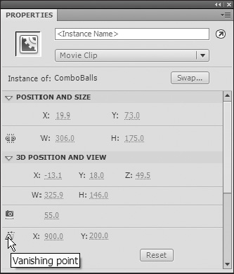
Figure 5-10. Setting vanishing point properties
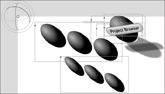
Figure 5-11. Global 3D showing a vanishing point for all movie clips on the stage
For example, if you locate the vanishing point at the upper-left corner of the stage (0, 0), increasing the value of the z property of a movie clip moves the movie clip away from the viewer and toward the upper-left corner of the stage.
Because the vanishing point affects all 3D movie clips, changing it also changes the position of all movie clips that have a z-axis translation applied.
The vanishing point is a document property that affects all movie clips that have z-axis translation or rotation applied to them. The vanishing point does not affect other movie clips. The default location of the vanishing point is the center of the stage.
To view or set the vanishing point in the Property inspector, a 3D movie clip must be selected on the stage. Changes to the vanishing point are visible on the stage immediately.
To set the vanishing point, follow these steps:
- On the stage, select a movie clip that has 3D rotation or translation applied to it.
- In the
Property inspector, enter a new value in theVanishing Pointfield, or drag the hot text to change the value. Guides indicating the location of the vanishing point appear on the stage while dragging the hot text.
To move the vanishing point back to the center of the stage, click the Reset button in the Property inspector.
Figure 5-12 shows three balls with a vanishing point and the 3D Rotation tool's controls with the combined movie clip rotated slightly compared to the same three balls not rotated in the figure. Keep in mind that you are not actually rotating 3D objects but only 2D objects with 3D effects. See Figure 5-13 a little later in the chapter for what happens if you rotate too far.
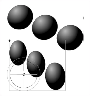
Figure 5-12. The three balls selected with the 3D Rotation tool
Rotating a multiple-object selection in 3D space
To rotate a selection of multiple objects in 3D space, follow these steps:
- Select the
3D Rotationtool in theToolspanel (or press W). - Verify that the tool is in the mode that you want by checking the
Globaltoggle button in theOptionssection of theToolspanel. Click the button or press D to toggle the mode between global and local. - Select multiple movie clips on the stage.
- The
3D Rotationcontrols appear overlaid on the most recently selected object. Place the pointer over one of the four rotation axis controls. The pointer changes when over one of the four controls. - Drag one of the axis controls to rotate around that axis or the free rotate control (outer orange circle) to rotate x and y simultaneously.
- Drag the x-axis control left or right to rotate around the x axis. Drag the y-axis control up or down to rotate around the y axis. Drag the z-axis control in a circular motion to rotate around the z axis.
The 3D center point, which appears at the center of the rotation guide, controls all of the selected movie clips.
To relocate the 3D rotation control center point, do one of the following:
- To move the center point to an arbitrary location, drag the center point.
- To move the center point to the center of one of the selected movie clips, Shift–double-click the movie clip.
- To move the center point to the center of the group of selected movie clips, double-click the center point.
The location of the rotation control center point for the selected object appears in the Transform panel as the 3D center point. You can modify the location of the center point in the Transform panel.
Rotating objects in 3D space
You rotate movie clip instances in 3D space with the 3D Rotation tool. A 3D rotation control appears on top of selected objects on the stage. The x control is red, the y control is green, and the z control is blue. Use the free rotate control to rotate around the x and y axes at the same time.
The default mode of the 3D Rotation tool is global. Rotating an object in global 3D space is the same as moving it relative to the stage. Rotating an object in local 3D space is the same as moving it relative to its parent movie clip if it has one. To toggle the 3D Rotation tool between global and local modes, click the Global toggle button in the Options section of the Tools panel while the 3D Rotation tool is selected. You can temporarily toggle the mode from global to local by pressing D while dragging with the 3D Rotation tool.
The 3D Rotation and 3D Translation tools occupy the same space in the Tools panel. Click and hold the active 3D tool icon in the Tools panel to select the currently inactive 3D tool.
By default, selected objects that have 3D rotation applied appear with a 3D axis overlay on the stage. You can turn off this overlay in the General section of Flash Preferences.
Rotating a single object in 3D space
Select the 3D Rotation tool in the Tools panel (or press W). You'll get a result similar to what you see in Figure 5-13.
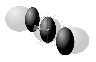
Figure 5-13. The three balls with the 3D Rotation tool handles
But of course that may be what you wanted.
If you need a variety of graphic effects without duplicating movie clips in the library, the 3D properties of movie clip instances in your FLA file may be sufficient. If you edit a movie clip from the library or in edit-in-place mode, the 3D transforms and translations that have been applied are not visible. When editing the contents of a movie clip, only 3D transforms of nested movie clips are visible.
If you have 3D objects on the stage, you can add certain 3D effects to all of those objects as a group by adjusting the perspective angle and vanishing point properties of your FLA file. The perspective angle property has the effect of zooming the view of the stage. The vanishing point property has the effect of panning the 3D objects on the stage. These settings only affect the appearance of movie clips that have a 3D transform or translation applied to them.
In the Flash authoring tool, you can control only one viewpoint, or camera. The camera view of your FLA file is the same as the stage view. Each FLA file has only one perspective angle and vanishing point setting.
To use the 3D capabilities of Flash, the publish settings of your FLA file must be set to Flash Player 10 and ActionScript 3.0. Only movie clip instances can be rotated or translated along the z axis. Some 3D capabilities are available through ActionScript that are not available directly in the Flash user interface, such as multiple vanishing points and separate cameras for each movie clip.
For a video tutorial about 3D graphics, see "Working with 3D Art" at www.adobe.com/go/lrvid4059_fl.
3D space movement
When you want to move movie clip instances in 3D space, you do it with the 3D Translation tool. Select a movie clip with the tool, and you will see its three axes, x, y, and z, appear on the stage on top of the object. Figure 5-14 shows this tool; although you can't see the colors in this figure, on your screen the x axis is red, the y axis is green, and the z axis is blue.
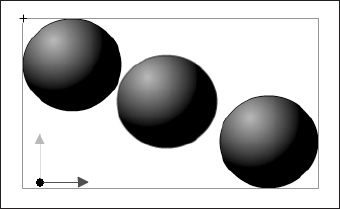
Figure 5-14. The three balls with the 3D Translation tool off palette, left of the stage
The 3D Translation tool default mode is global. Moving an object in global 3D space is the same as moving it relative to the stage. Moving an object in local 3D space is the same as moving it relative to its parent movie clip. You can temporarily toggle the mode from global to local by pressing D while dragging with the 3D tool or by clicking the Global toggle button in the Options section of the Tools panel while the 3D Translation tool is selected. Figure 5-15 shows the three balls after changes with the 3D Translation tool.
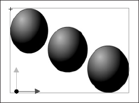
Figure 5-15. Use the 3d translation tool to apply a translation to the three balls.
As mentioned previously, the 3D Translation and 3D Rotation tools occupy the same icon.
In the Tools panel, click and hold the active 3D tool icon in the Tools panel to select the currently inactive 3D tool.
By default, selected objects that have 3D translation applied appear with a 3D axis overlay on the stage, which you can turn off in the General section of Flash Preferences.
Moving a single object in 3D space
The 3D effects are most effective with apparent movement; here is how to get started. There are many ways to add spices, and the only limit is your creativity.
To move an object in 3D space, follow these steps:
- Select the
3D Translationtool in theToolspanel (or press G to select it). - Set the tool to local or global mode. Check the
Globaltoggle button in theOptionssection of theToolspanel to be sure that the tool is in the mode you want. Click the button or press D to toggle the mode. - Select a movie clip with the
3D Translationtool. - Move the object by dragging with the tool. Move the pointer over the x-, y-, or z-axis controls. The pointer changes when over any of the controls.
The x- and y-axis controls are the arrow tips on each axis. Drag one of these controls in the direction of its arrow to move the object along the selected axis. The z-axis control is the black dot at the center of the movie clip. Drag the z-axis control up or down to move the object on the z axis.
To move the object using the Property inspector, enter a value for x, y, or z in the 3D Position and View section of the Property inspector.
Move an object on the z axis, and its apparent size changes. The apparent size appears in the Property inspector as the Width and Height read-only values in the 3D Position and View section. Note in Figures 5-14 and 15-15 that the apparent size changed from left to right as we position on the z axis.
Moving multiple objects in 3D space
When you select multiple movie clips, you can move one of the selected objects with the 3D Translation tool, and the others move in the same way. Try it yourself:
- Set the
3D Translationtool to global mode to move each object in the group in the same way (in global 3D space), and then drag one of the objects with the axis controls. - To move the axis controls to another object, shift–double-click one of the other selected objects.
Set the 3D Translation tool to local mode to move each object separately in the group in the same way in local 3D space, and then drag one of the objects with the axis controls. Shift–double-click one of the selected objects to move the axis controls to that object.
You can also move the axis controls to the center of the multiple selection by double-clicking the z-axis control. Shift–double-click one of the selected objects to move the axis controls to that object:
- Verify that the tool is in the mode that you want by checking the
Globaltoggle button in theOptionssection of theToolspanel. Click the button or press D to toggle the mode between global and local. - Select a movie clip on the stage.
- The
3D Rotationcontrols appear overlaid on the selected object. If the controls appear in a different location, double-click the control center point to move it to the selected object. - Place the pointer over one of the four rotation axis controls. The pointer changes when over one of these controls.
- Drag one of the axis controls to rotate around that axis: Drag the x-axis control left or right to rotate around the x axis. Drag the y-axis control up or down to rotate around the y axis. Drag the z-axis control in a circular motion to rotate around the z axis. Or use the free rotate control (outer orange circle) to rotate x and y simultaneously.
- To relocate the rotation control center point relative to the movie clip, drag the center point. This lets you control the effect of the rotation on the object and its appearance.
- Double-click the center point to move it back to the center of the selected movie clip.
The location of the rotation control center point for the selected object appears in the Transform panel as the 3D Center Point property. You can modify the location of the center point in the Transform panel.
Transform panel rotation
To use the Transform panel for rotation, follow these steps:
- Open the
Transformpanel (Window
Transform). - Select one or more movie clips on the stage.
- To move the 3D rotation point, enter the desired values in the
3D Center Point X, Y, andZfields.
Perspective angle
The perspective angle property of an FLA file controls the apparent angle of view of 3D movie clips on the stage.
The apparent size of 3D movie clips and their location relative to the edges of the stage are adjusted by increasing or decreasing the perspective angle effects. By increasing the perspective angle, you make 3D objects appear closer to the viewer. By decreasing the perspective angle, you make 3D objects appear further away. The effect is like zooming in or out with a camera lens, which changes the angle of view through the lens.
All movie clips with 3D translation or rotation applied to them are affected by changes to the perspective angle property. The perspective angle does not affect other non-3D movie clips. The default perspective angle is 55 degrees of the view, like a normal camera lens. The range of values is from 1 degree to 180 degrees.
To view or set the perspective angle in the Property inspector, as shown in Figure 5-16, a 3D movie clip must be selected on stage. Changes to the perspective angle are visible on the stage immediately.
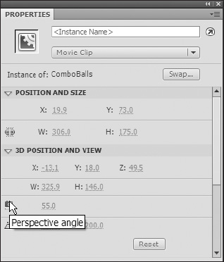
Figure 5-16. Setting the perspective angle in the Property inspector
The perspective angle changes automatically when you change the stage size so that the appearance of 3D objects does not change. You can turn off this behavior in the Document Properties dialog box.
To set the perspective angle, follow these steps:
- On the stage, select a movie clip instance that has 3D rotation or translation applied to it.
- In the
Property inspector, enter a new value in the perspective angle field (currently 55.0 in Figure 5-16) or drag the hot text to change the value.
Figure 5-17 shows two perspectives of the same image, with Figure 5-18 showing changes in one of those perspectives.
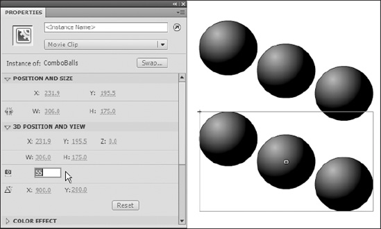
Figure 5-17. Showing two different perspectives of the same image
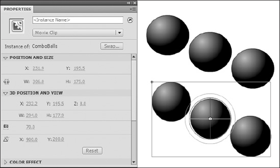
Figure 5-18. One of the two perspectives has been changed by 15 degrees.
Summary
Now you should have plenty of spicy flavors to add to your Flash soup: in this chapter we showed you how you can blend two or more objects in a number of different ways and apply filters to get special effects. Then we demonstrated how to add another perspective, literally, with 3D so you can make things look more like they do in the real world and less like a flat painting.
In this chapter, we covered the following topics:
- Blends
- Filters
- 3D transformations