CHAPTER 7
PLAYING WITH DOLLS: INTRODUCING FLASH IK
One of the most highly anticipated features to be included with Flash CS4 is the addition of inverse kinematics (IK) for aiding animation. Inverse kinematics is something that has been eagerly awaited and widely considered long overdue for Flash designers. Up to now it was something only achievable in Flash using advanced ActionScript. IK tools are staples in many other 3D and animation programs used in professional multimedia development. Typically, IK systems are used to animate complex anatomies such as those of humans, animals, and machinery. Fortunately, the developers of Flash have answered the cries of the many animators out there and added a set of tools for governing kinematics with great ease. And the benefits of this technology can now be harnessed in the Flash design-environment.
In this chapter we will explore how this new functionality benefits Flash designers. You will be introduced the Bone and Bind tools, which are the two primary tools used to create IK systems. We will then use these tools to apply IK systems to symbols and shapes.
What is kinematics?
Kinematics is the area of mechanics associated with the motion of objects, without consideration for that object's own mass or the external forces acting on that object. Wow, seems intimidating—but don't worry, it is not. In everyday language, kinematics simply describes how objects move.
Inverse kinematics
Though there are several types of kinematics, as far as Flash designers are concerned, we only need to concern ourselves with inverse kinematics. As mentioned previously, kinematics primarily focuses on the motion of objects. Inverse kinematics is a type of kinematics that explains the motion of specific systems. A system is essentially a group of connected parts (like a skeleton, hence the bone analogy). And, kinematics is responsible for governing how those parts move in relation to one another.
For example, an arm, along with the hand and shoulder, is a system comprised of three primary segments (hand, forearm, humerus) and three primary joints (wrist, elbow, shoulder). The movement of one of these parts affects the position of the others. It is also important to point out that these systems also must have a base, or fixed end, like a shoulder is fixed to the torso. And, they must have a free end, like a hand.
Inverse kinematics is then specifically responsible for explaining how these systems move when a change is applied to the free end. Think of this like a paper doll, marionette, or even an action figure to some extent. When the free end of an appendage is moved or positioned, the rest of the system needs to move as well, like pulling on a chain.
It is through these principles of IK that Flash designers are granted a greater degree of control when working with complex systems. Once applied, the IK functionality in Flash makes animating these complex structures as simple as positioning a paper doll.
An arm or a leg: Experimenting with IK
Now that you are an expert in the concept of IK, it's time to put that knowledge to good use. First, we are going to take a look at building a basic, three-segment IK structure. Here we will discuss the ins, outs, and subtleties of using this tool set. This example will also get you ready to animate a more complicated humanoid system later in this chapter.
Getting started with the arm
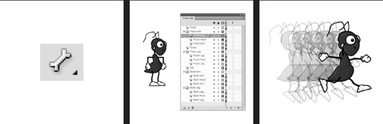
You can start off by opening ch07_01_start.fla found in the folder of the book's source file samples. You will notice a single black rectangle on the stage. This rectangle is a movie clip symbol that we have created for you to use in this example. It represents one of the three segments that we will need to create our three-part IK system. What you are going to need to do here is create two additional segments.
As shown in Figure 7-1, the best way to achieve this is to simply use the original segment and clone or duplicate it across the stage. The easiest way of doing this is to hold down the Alt key (Option key on a Mac) and select the original segment. While still holding the down the left mouse button, you can then drag the new segment out on the stage. Go ahead and repeat this to create all three segments.
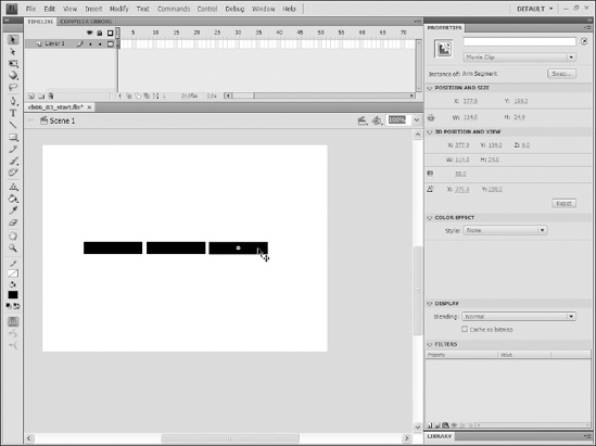
Figure 7-1. Three movie clips prior to IK rigging
Now that we have all three segments on the stage, we can simply link them together using the new Flash IK Bone tool.
The anatomy of a bone
For those of you who have never done any animation before, we cannot begin to explain the amount of time the Flash IK Bone tool is going to save you now that it is available. In addition to being a time saver, it also offers a cleaner and more organized approach to the way animations are produced.
The IK bone, as illustrated in Figure 7-2, is comprised of these three primary components, which are listed in the order of their creation:
- Parent joint: The parent joint is the circle located near the larger end of the-triangle.
- Bone: The bone is the triangular shape that connects the two joints.
- Child joint: Subsequently, the child joint is the circle located at the smaller end of the triangle.
Figure 7-2. IK bones are comprised of three main parts: a parent joint, a bone, and a child joint.
Adding bones to the arm
Now, let's take a crack at adding IK bones to the segment created earlier in this section. To add bones, follow these steps:
- Select the
Bonetool, shown in Figure 7-3, from the FlashToolspanel.

Figure 7-3. The
Bonetool is used to add IK bones to symbols and vector shapes. - Using Figure 7-4 as a reference, move the cursor to the center of the leftmost edge of the left segment.
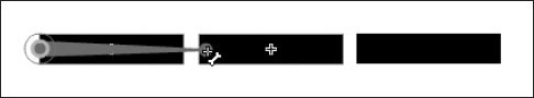
Figure 7-4. Bones can be applied by dragging the
Bonetool from one symbol to another. - Press and hold the left mouse button to begin drawing the first bone of your IK system.
- With the left mouse button still held down, move the cursor to the center of the leftmost side of your second segment and release the mouse button. You should now see your first bone connecting the first two segments of your system.
By repeating the process and dragging out a second bone between the second and third segments, you will successfully link all three of these segments into one structured IK system. Once you have completed the linking of the three segments, try selecting each of them with the Selection tool and moving them around the stage. You should notice that all elements in the system move with respect to one another depending on which segment you try to move.
You should also take particular notice of the fact that after completing the process of rigging an IK system, all symbols used in that system will be moved to one new layer as shown in Figure 7-5. This new layer—denoted by a running character in the Layers panel—is referred to as an armature.
Figure 7-5. IK structures are grouped together into an armature and moved to a new layer.
Controlling the motion of specific bones
You have just seen how quickly and efficiently you can create a simple three-segment system using the new Flash IK tools. And though it may not be something worthy of hanging on the refrigerator, it certainly is your first step toward animation mastery. Before we get into the heavy lifting, there is one more thing we would like to show you with regards to the specific nature of individual IK bones.
Like most other elements in the Flash development environment, individual IK bones are able to have specific parameters applied to them through the use of the Property inspector. This functionality becomes incredibly advantageous when a designer begins to develop more sophisticated systems—like humanoids or octopods. In order to access this functionality, you will need to select a specific bone within your armature. When the bone is selected, it will turn a color that is complementary to the color of the entire system.
Upon selecting a specific bone, the Property inspector will change to reflect the specific parameters of that particular bone. It is important to understand that the parameters applied to a specific bone in the Property inspector directly influence that bone's parent joint. As noted earlier, the parent joint is the circular part of the bone located next to the larger end of the bone's triangular shape. Therefore, if we adjust the rotation of a bone, it will control how the bone rotates around its parent joint.
As shown in Figure 7-6, four types of parameters can be applied to a bone through the Property inspector once it has been selected:
- Joint location: Though the
Locationsection gives specific information relative to the position of the selected bone, you are unable to change the position from theProperty Inspector. What can be changed here is theSpeedparameter. The speed at which a bone can move will give the bone the illusion of weight in an animation. - Joint rotation: The set of parameters under
Joint: Rotationallows you to control the rotation of a bone around its parent joint. You have the ability to enable, disable, and constrain or limit the range of motion. - Joint x translation: The set of parameters under
Joint: X Translationallows you to control a parent joint's motion along the x axis, which is horizontal or left-to-right motion. - Joint y translation: The set of parameters under
Joint: Y Translationallows you to control a parent joint's motion along the y axis, which is vertical or top-to-bottom motion.
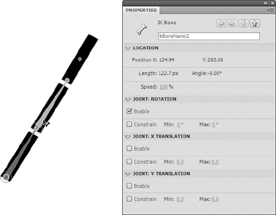
Figure 7-6. A selected bone and the subsequent Property inspector parameters
Let's apply constraints to some specific bones.
Applying constraints to specific bones
For starters, go ahead and select the first bone in your system from ch07_01.fla. Remember, when a bone is selected, it will highlight with a color complementary to the rest of the bones in that system. Now pay close attention to the parent joint. You may have noticed a thin circle that surrounds it. This circle, as shown in Figure 7-7, indicates that joint rotation has been applied to this particular joint.
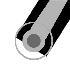
Figure 7-7. The constraint indicator is used to show which contraints have been applied to a bone.
Let's go ahead and remove this joint's ability to rotate.
- In the
Property inspectorunder theJoint: Rotationsection, uncheck the check box next to the wordEnable. You should notice that the constraint indicator circle disappears.
Try to move the system by dragging its various segments. You will see that arm no longer has motion from what we will call the shoulder joint.
Next let's change the parameters on the second bone in our system.
- After selecting this bone, disable the joint rotation by unchecking the check box next to
EnableunderJoint: Rotationin theProperty inspector. - Enable the y translation by checking the check box next to
Enableunder theJoint: Y Translationsection in theProperty inspector.
Again, you should notice that the circle around this joint has disappeared. You will also notice that a small line with two arrowheads has now appeared along the parent joint's vertical axis. If you haven't already guessed, this line is the constraint indicator for y-translation.
As you learned earlier, x translation and y translation parameters are responsible for constraining the motion of a parent joint to a linear motion in either a vertical or horizontal direction. Try moving the system now. You'll see that the first segment basically does nothing, the second segment is now restricted to moving up and down, and the third segment still freely spins in 360 degrees.
Constraining bone movement
Finally, notice that the Joint: Rotation, Joint: X Translation, and Joint: Y Translation sections of the Property inspector all contain a Constrain check box option. With these. parameters, you can limit the range of motion for any parent joint associated with the Constrain.
For example, the second segment in our system can move up and down with no apparent limitation. Select the bone associated with that section. Then check the check box next to Constrain under Joint: Y Translation in the Property inspector. You should immediately note two specific changes. The arrowheads on the orange line that indicate y translation on the parent joint of that bone have changed to straight lines. You should also notice that the Min and Max values next to the Constrain check box have become active. It is now possible to edit the Min and Max values to limit the total range of motion for that joint. This is also true for joint rotation.
Now that you are familiar with controlling bones and the IK system, let's try animating the arm.
Creating motion with an IK system
All right, we think it's about time you saw something move on its own, don't you? This is where the real power of the Flash IK tools comes to light. So far in this chapter we have primarily focused on the construction of a simple three-segment IK structure. And so far, it probably doesn't seem terribly difficult to work with the Flash IK tools. We hope this is the case.
In this section we are now going to examine how IK animation is different from traditional methods of Flash animation. Then we will apply these techniques to the arm we created in the previous section.
Comparing IK to motion tweening
Let's briefly examine the file ch07_02.fla, found in this chapter's working files. This file is more or less the same arm system you have been experimenting with. The primary difference is that it has been constructed using traditional (motion) tweening methods. And though the tweening model in Flash CS4 is significantly easier to work with than previous versions, it still poses a tremendous amount of difficulty when trying to articulate complex systems.
When examining ch07_02.fla, you should immediately notice that it looks pretty much exactly like the ch07_01_start.fla file you have been working with so far in this chapter. There are three black rectangles that need to be animated to mimic the motions of an arm.
The first primary difference to point out is the presence of two additional layers, as shown in Figure 7-8. Unlike the IK system that automatically organizes all three segments on one layer, motion tweening requires that each symbol reside on its own layer.
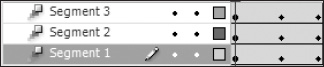
Figure 7-8. Animating with traditional tweening methods requires a more complicated layer structure.
Imagine how complicated this would become if you were animating several human characters. Even the simplest human character would need between five and eight parts working in tandem to achieve the illusion of animation. Add more characters, and the complexity of the layer structure alone becomes a nightmare.
Next, take a moment to see how the ch07_02.fla animation works by moving the playhead slowly from frame 1 to frame 10. You should notice that as you approach frame 3, the three segments of this animation begin to overlap. This is definitely not very effective. Therefore, in addition to increased layer management, a designer would also be responsible for an increased number of intermittent tweaks to get the animation to behave in the desired manner. You may close ch07_02.fla.
Animating the arm
Fortunately, we now have the ability to control animation quickly and efficiently with the Flash IK tools. Let's go ahead and animate the arm in ch07_01_start.fla.
Remember that in animation we need keyframes. When dealing with IK armatures, keyframes are referred to as poses. Therefore, we will need to pose our armature in the manner in which we would like it to look. You have the option here to pose your armature in any manner you see fit. And, if you would like, please feel free to play with the Property inspector parameters for each bone to help you gain more familiarity. For the sake of comparison, the sample files ch07_03_start.fla and ch07_03_finish.fla will be improving on the throwing animation demonstrated in ch07_02.fla.
Your armature should be set in the proper starting point, as decided by you. The next thing that you will need to do is set an end position. Animation, of course, is the change of state over time. So we will need to add a few frames. This has been made extremely easy in Flash CS4, as you will see by following these steps:
- Position your mouse over frame 1 of the
Armature_1layer of your current working file. Your mouse cursor should change from a white arrow to a short black line with two arrowheads, which are pointing left and right. - Go ahead and select frame 1 by clicking your mouse. Frame
1should now be highlighted in blue. - With the mouse button still pressed, you can drag to the right and highlight additional frames to add to your animation. We suggest highlighting to frame 10.
- Once you have highlighted the desired number of frames, you may release the mouse button, and additional frames will be added to the timeline.
- Make sure the playhead is at the last frame of your animation. For example, we have set our playhead to frame 10. Once you have done this, arrange your armature in a different pose. Move the playhead back and forth across the timeline, and see what you get.
Not bad. Let's add an intermittent pose. Position the timeline approximately halfway between the beginning and end of your animation. As shown in Figure 7-9, we have positioned our playhead to frame 5. Now we can add a new pose.
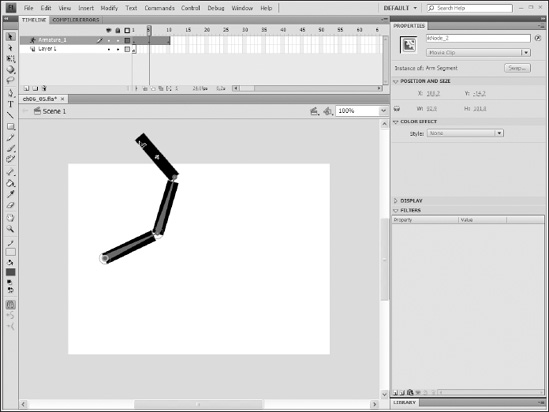
Figure 7-9. Insertion of an intermittent keyframe
As you learned earlier, in order to achieve a change in an animation, you need a keyframe. Remember, keyframes in IK animations are called poses. There are a few ways you can add a new pose to the timeline in Flash. We will explain the two most commonly used and efficient methods to do this.
The first method is to right-click (Ctrl-click on a Mac) a frame:
- Move the mouse cursor over a frame in the timeline where you would like to place a new pose.
- Right-click (Windows) or Ctrl-click (Mac).
- Select
Insert Posefrom the context menu.
As an alternative, you can also add a pose simply by adjusting the armature as follows:
- Move the playhead to the desired position for adding a new pose.
- Reposition the armature as needed, and a keyframe is automatically added.
Since the repositioning of the armature is required for all other methods of adding poses to armature animations, the second option should be considered the most efficient way to perform this task.
Using one of the aforementioned methods for including poses in an armature animation, you may now add a second pose to your animation. Sticking with the examples from earlier, ch07_03_finish.fla demonstrates a simple throwing motion.
That's it! You have successfully created an animation using the Flash IK tools. It may not seem like much yet, but you will be applying these techniques to a more complicated structure very shortly. And, though it may not be immediately evident, these techniques will save you hours in production.
Author-time versus runtime IK animation
Before all this newfound knowledge can be brought together into something useful, there is one more thing that is worth mentioning. Flash IK tools have the ability to be set for either author-time use or runtime use. If you are not familiar with the terms "author time" and "runtime," don't worry. Author time simply means something that happens while you are creating or authoring your Flash projects in the Flash IDE, and runtime refers to something that happens when you play or run your Flash movies.
If you still have your file open from the previous example, you are going to use it for one last example. If you happened to close it, don't worry—you can simply open-ch07_03_finish.fla.
To switch between author-time and runtime IK animation, all you need to do is select any frame in the Flash timeline on the Armature_1 layer. You will notice that the entire timeline associated with this layer is highlighted blue. When this happens, you should also notice that the Property inspector reflects various parameters that can be applied to this specific animation. This is demonstrated in Figure 7-10.
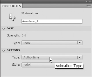
Figure 7-10. The timeline properties for a pose layer in the Property inspector
For now, take a look at the Options section. The Style drop-down menu allows you to determine the type of bones that are used in your armature:
Wire: Displays bones in the familiar triangular fashion. The primary difference is that these triangles are represented by outlines also known as wireframes.Solid: Serves as the default display setting for bones. It is what you should be used to working with in this chapter. Bones are represented by filled triangular shapes of varying color.Line: Simply displays bones as single individual lines of varying colors.
The other drop-down menu shown in the Options section of the Property inspector is the Type drop-down. It is here that you have the ability to set the IK animation to Authortime or Runtime. Select Runtime from the Type drop-down.
Oops! You may have noticed the screen prompt shown in Figure 7-11 warning you of an error with your animation. This is actually quite all right.
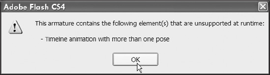
Figure 7-11. An alert window is triggered when runtime animation is used improperly.
The reason for this error is that IK animations that are to be set for runtime are not allowed to have more than one pose. Why, you ask? Well, if the armature is set to be used at runtime, you will have the ability to pose and interact with it when the Flash movie is playing. If there are several poses defined at author time, the armature will want to animate itself. You can't move an object and have it move itself at the same time.
To remedy this you will need to do the following:
- Delete frames 2 through 10 of the
Aramture_1layer in your movie.
You can do this by selecting frames 2 through 10, right-clicking (Ctrl-clicking on a Mac), and then selectingRemove Framesfrom the context menu. - You may now return to the
Property inspectorand change theTypedrop-down fromAuthortimetoRuntime. - Test this movie.
You are now able to move your IK armature in your published SWF files just as you were able to on the stage. If you tried this with Authortime still selected, you would be unable to move your armature.
Using IK with complex anatomies
There is no doubt that the true purpose of the Flash IK tools is for use with complex anatomies such as human character animations. In the next section we are going to rig a simple cartoon character to help you better understand this concept. When we finish, you should have a thorough understanding of this process and how to apply IK rigs to even more complex systems in the future.
Simple anatomy: A little help from Leonardo
Setting up a human IK rig is going to be a bit more complicated than that of an arm. After all, the human design has two arms! Additionally, your human armature will introduce you to the concept of branching. Though this is not a particularly difficult concept to understand, it may not be obvious for those who have no prior experience with this sort of animation. Therefore, we are going to take a second to examine the anatomy of the human IK rig before we begin.
Using the popular drawing of Leonardo da Vinci's Vitruvian Man as our model, we have the ability to examine just how one would begin to apply an IK system to a human being. If you have ever spent time in a gym training for a sport or watching ESPN right before the sun comes up, you may have heard the term "power core." Also referred to as the core or powerhouse in Pilates, the power core refers to the center of the body. This area is traditionally comprised of the abdomen, lower back, and often the buttocks and inner thighs. It is referred to as the power core because it is responsible for the stabilization of the entire body. Essentially, the human body's mechanics are grounded in the abdomen.
We are always amazed by the apparent unintentional nature of art imitating life. You could, for example, start constructing your IK armature from the head of a figure and get it to work to some degree. You could also begin your armature in the chest area, and that would probably work pretty well, too. This may, however, create a rotation problem later in the hips of many armatures. If you plot your first bone at about the belly button, that will give you the most efficient apparatus. Even in the designing of an IK animation, the abdomen serves as the best center.
Subsequently, all other bones in the armature branch out from this center point. As you can see from Figure 7-12, this armature is comprised of three primary branches. The first of these is the parent, or root, bone, which starts at the belly button and traverses to the chest, the neck, and finally the head. The other two primary branches are the legs. For these, bones travel through the hips, thighs, lower legs, and joint at the ankle.
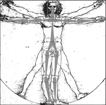
Figure 7-12. An IK armature applied to Leonardo da Vinci's Vitruvian Man
Finally, you may now be wondering the obvious question about the classification for the arms. Well, the obvious answer is that they are secondary branches off of one of the primary branches. These systems can become quite sophisticated if necessary. Imagine that you are going to detail the armature of a human to the finger level. Fingers are a three-part system in their own right. Therefore, your child branches would have child branches (grandchildren). And, the chances of getting three levels of branching are probably a little better than you might think.
Applying IK to a human character
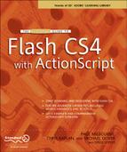
To begin adding an IK rig to a character, the first thing to do is familiarize yourself with the assets that will be used in the file. In the real world, you will want to have this planned out in advance. In this case, we have supplied you with a file that contains all the graphical elements that you will need to create this animation.
For this example, we will start with the working file ch07_04_start.fla. Open this file and explore the layer structure as shown in Figure 7-13. You should notice that the graphics for this file have been organized as a head, a torso, a hip, two legs, and two arms. The layers have also been organized with respect to the physiology of the character. That is, the front arm pieces are in front of the torso, and the back arm pieces are behind the torso. This stacking order also holds true for the head, legs, and so forth.
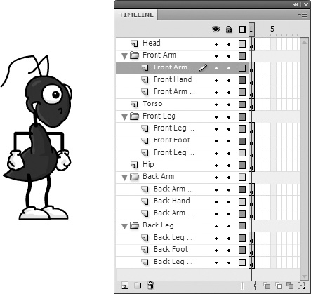
Figure 7-13. Body parts of any character should be arranged logically.
Before we get started, it is important we point out that the most complicated part of this process will be keeping the character organized. As you add pieces to the armature, Flash will automatically pull pieces off of their respective layers and add them to the armature layer. This will, without question, change the preestablished stacking order of each graphic.
Additionally, it will also be somewhat difficult at first to get the feel for adding each new bone. Until you have become comfortable with this process, you will probably feel that each graphic is getting in the way of the others. Because of this, we will offer the following suggestions.
- Utilize the outlining feature for each layer.
While you are rigging the character, we suggest that you immediately turn on outlines for the armature layer so you can see the pieces that have not yet been added. This will also help you position the bones more accurately. - Move pieces out of the way.
You should notice from Figure 7-13 that several pieces overlap. For example, the front arm overlaps the hip piece and top portion of the front leg. You will more than likely want to move the front arm out of the way to get access to the underlying pieces. - Reorder layers as you work.
As mentioned earlier, adding graphics to the armature will change the stacking order of the original layout. It may be advantageous to manually change the position of layers as you work. This will also make it easier to access certain graphics throughout the process. - Lock and unlock layers as needed.
To avoid confusion and inadvertent symbol selection, it is recommended that you utilize the locking and unlocking of layers as you work.
Now that we are ready, let's get started!
Setting up the core
The first thing we will want to do is establish the root of our structure. As discussed earlier, the best place to start is in the abdomen area. In this case, our character's midsection is broken into two primary parts: the torso and hip symbols. Of these two pieces the most centrally sound is going to be the hip symbol. The hip will give us direct access to both the legs and upper body.
You can begin your armature by doing the following:
- With the timeline open, unlock the
Head, Torso, andHiplayers of the character. - Hide the front arm graphics by clicking the
Show/Hide layerbutton for theFront Armfolder's layer. - Make sure the
Property inspectoris open to allow you to add constraints. - Select the
Bonetool from theToolspanel and draw your first bone from the hip graphic to the upper portion of the torso graphic.
Once your first bone is added, your stage should look similar to Figure 7-14. The center of the hip has been connected to the torso right near the center. The Armature_1 layer has had the outline option selected so that items will become transparent as they are added to the armature.
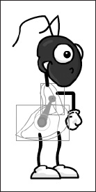
Figure 7-14. The first step when creating an IK rig is establishing the parent, or core.
- Draw a second bone from the child joint of your first bone to the head symbol just at the base of the neck.
- Select this second bone. In the
Property inspector, uncheck the box next toEnableunder theJoint: Rotationoptions. - Select the first bone. Check the box next to
Enableunder theJoint: X Translationoptions. This will later allow you to move the character from left to right.
Adding the arms
Next we will want to add the arms for the character. The arms will be secondary systems that originate from the joint that is located on the character's chest. For this we will also be adding more constraints for the shoulders, elbows, and wrist joints.
To add the arms, follow these steps:
- Unlock the
Back Armlayer, and drag that layer above theArmature_1layer. - With the
Bonetool selected, drag a bone from the chest joint to the top of the upper portion of the back arm as shown in Figure 7-15. When the cursor changes to a white bone with the plus sign (also shown in Figure 7-15), this signifies the ability to add a new bone.
Figure 7-15. When the
Bonetool cursor changes to a white bone, a new bone can be added. - Add a bone for this arm that connects the shoulder to the elbow.
- Add a bone from the elbow to the wrist.
- You want to constrain the motion of the elbow. To do this, select the bone going from the elbow to the wrist. In the
Property inspector, check the box next toConstrainunder theJoint: Rotationoptions. Set the Min property to−85and theMaxproperty to0. - Repeat the preceding steps to add the bones to the front arm. Make sure that the layers are unlocked and visible.
Once you have finished rigging both arms, we strongly suggest that you move them out of the way so they don't impede the rigging of the rest of your character. When you have finished with the arms, you should have a character that resembles the image shown in Figure 7-16.
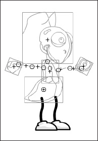
Figure 7-16. The arms of the character are moved to help the rigging process.
Adding the legs
Adding legs to the IK system is actually very similar to adding the arms. When adding the legs, we are going to use the hip bone as the parent. Adding the legs will be a bit more difficult, as the graphics are very close together.
To add the legs, follow these steps:
- Unlock the Front Leg and Back Leg folders' layers.
- Starting with the front leg, create a new bone by dragging the
Bonetool from the hip to the upper leg. Figure 7-17 shows that a bone can be started by mousing over any part of a symbol. Figure 7-18 shows you how to apply this bone.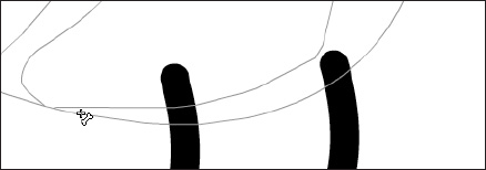
Figure 7-17. The
add boneicon will appear when mousing over any symbol with a bone already applied to it.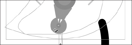
Figure 7-18. The hip bone is connected to the leg bone. We know!
- Create a bone that connects the upper leg joint to the lower leg at the knee.
- Add the bone that connects the lower leg to the foot at the ankle.
- Select the bone that connects the lower leg to the foot. In the
Property inspectorcheck the box next toConstrainunder theJoint: Rotationoptions. Set theMinproperty to−60and theMaxproperty to135. - Repeat these steps to add bones to the back leg.
Once you have added the bones to both legs, you should have a character like the one shown in Figure 7-19.
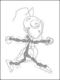
Figure 7-19. All bones have been added to the character.
Cleaning up your character
Before we can begin the animation process, we will need to do a bit of tidying up. The process of adding an IK system to your character has no doubt wreaked havoc on the general organization of things.
- Delete all layers in your timeline except the
Armature_1layer. All of your graphics have been moved to this layer. Therefore, none of the other layers are needed. - Turn off the outlines option for the
Armature_1layer. You will now see how crazy everything has really become. - To fix the stacking order of the character pieces, right-click (Ctrl-click on a Mac) each symbol and select
Adjustfrom the context menu. Using a combination ofBring to FrontandSend to Back, rearrange the stacking order of each symbol so that it is restored to its original position. - It may also be necessary to slightly adjust the positions of specific symbols. To adjust the positions of a specific symbol, select that symbol with the
Subselectiontool while holding the Alt key (Option key on a Mac). You can also use theTransformtool to tweak the symbol's transform point if needed.
Animating the character
Animating your Flash IK character is actually the easiest part of the whole process. All you need to do is add some frames and position the armature in a new pose, and the character will animate.
To animate the character, do the following:
- Pose the armature in a desired starting position.
- As shown in Figure 7-20, add frames by mousing over frame 1 of the timeline. When the cursor becomes the double arrow, drag out more frames on the timeline.

Figure 7-20. The double arrow allows designers to quickly add frames to the timeline.
- To create movement, simply move the playhead to a different frame on the timeline and change the position of your character to create a new pose as shown in Figure 7-21.

Figure 7-21. To add a new pose, simply reposition the armature.
- Finally, once you have created several positions for your character, test your movie. You will see your character animate across the stage (see Figure 7-22).
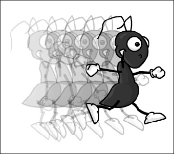
Figure 7-22. Characters will easily animate using the IK tools.
Now that you have seen how easy it is to animate a complex structure, experiment a bit. Try adding different constraints and new intermittent poses to see what you can come up with.
Using IK with shapes and the Bind tool
Another exciting feature of the Flash IK tools is the ability to use bones with vector shapes. This gives designers an incredible amount of increased control over the animation of vector shapes. Unlike symbol instances, which only allow one bone per symbol, shapes allow you to add as many bones as you need to create the animation you desire.
In addition to the ability to add multiple bones to a shape, designers also have the ability to add bones to multiple shape fills and strokes at the same time. In fact, during our research with this new functionality, we were able to add an IK system to a vector-based butterfly that was comprised of over 600 individual shapes! And, in a similar fashion to the way symbols are grouped, all shapes associated with a shaped-based IK system are grouped together on their own new pose layer.
Working with bones and vector shapes
Creating an IK shape object is an extremely easy process that can be summed up in the following steps:
- Select a vector shape in Flash.
- Select the
Bonetool from the FlashToolspanel. - Add a bone in exactly the same manner that you would add a bone to a symbol instance. Similarly, you can add bones to multiple shapes by simply selecting all shapes that are required for the animation, and then applying the bones using the Bone tool.
Selecting shapes for IK
To get some practice with this technique, let's take a look at ch07_star_start.fla, located in the sample files for Chapter 7. As you can clearly see, this is a very simple file comprised of one shape, which resides on one layer, which spans one frame. To add an IK system to this star, as shown in Figure 7-23, you need to make sure that the star is selected. So, go ahead and select the star with the Selection tool found in the Flash Tools panel. You will by now recognize that it is selected by the hash pattern that appears within the fill color.
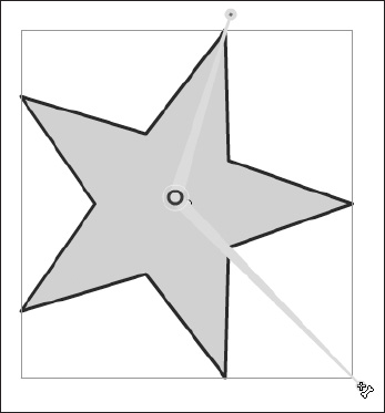
Figure 7-23. An IK bone being applied to a vector star shape
For just a moment it is worth drawing attention to the fact that the star has a blue stroke. If you were to add a bone to the star shape at our current point in this discussion, the blue stroke would be excluded. It is important that when you are using the Flash IK tools with vector shapes, you make sure that everything you want to animate is selected. For now, selecting the blue stroke with the star is simply a matter of double-clicking the star with the Selection tool. If in the future your shapes did happen to be independent from one another, you could simply draw a selection rectangle with the Selection tool or Shift-click all your shapes with the Selection tool.
Applying bones to a vector shape
Once your shapes are selected, you may add a bone using the Bone tool in the Flash Tools panel. In the exact same fashion as you would when adding bones to symbols, select the Bone tool and click the selected shape where you would like the root of your armature to be. Once you have clicked your shape, you can drag out a new bone in any direction.
One of the primary differences between shape bones and symbol bones is the fact that when dragging out bones with shapes, you do not have to attach the bone to anything else. Figure 7-23 shows that the child end of your IK bones can be positioned virtually anywhere.
Now that you have bones connected to your shape, you will notice that a new pose layer was created in Flash. You can also experiment with how the bones affect different aspects of the shape. Try experimenting with adding more bones and seeing how they too affect the transformation of the overall shape.
Further, you have the ability to create complex armatures with shapes. Figure 7-23 demonstrates a couple simple bones being added to the star shape. Imagine if you were to construct a human armature for the star like the one you constructed earlier for the cartoon character. You could theoretically animate a dancing star!
Regardless of what you do, it is inevitable that you will start to develop some fairly complicated armatures that may require some tweaking and adjusting. In many cases you may not have your joints in the exact place that they are needed. To adjust a joint's position, simply select that joint with the Subselection tool—also affectionately called the white arrow—and move the joint to the desired location. Should you find yourself in the unfortunate situation that a bone needs to be deleted, select the problematical appendage with the Selection tool and simply press Delete.
Using the Bind tool
As you no doubt noticed from your experimentations over the last few pages, working with IK and shapes sometimes delivers varying and unexpected results. To help with this issue and offer designers more control over their IK shapes, the fine people at Adobe have included a nifty little contraption known as the Bind tool. The Bind tool allows you to link various control points on your vector shape to specific bones within your IK rig. This tool can be used to link a bone to multiple control points or multiple bones to the same control point.
Accessing the Bind tool
To access the Bind tool, take a look at the Bone tool in the Flash Tools panel. You should notice a small black triangle in the lower-right corner of the tool. This triangle signifies that a tool is grouped with other tools or other sets of tools. In this case the Bone tool is grouped with the Bind tool. To activate the Bind tool, click the Bone tool and hold down the mouse button until a fly-out menu appears that contains both the Bone and Bind tools. From this fly-out menu, you may select the Bind tool shown in Figure 7-24. This tool can also be accessed by pressing Z.

Figure 7-24. To access the Bind tool, hold down the mouse button while selecting the Bone tool in the Tools panel.
Applying binds to shapes
To apply binding to your armature, select your IK shape object with the Bind tool. If your armature is already visible, select a specific bone with the Bind tool. As shown in Figure 7-25, when you select a bone, it will be signified by a red line. All applicable surrounding control points will be highlighted yellow. By this, we mean that not all control points on the shape will be active for each bone. Therefore, when this bone is moved during animation, only the yellow control points and strokes associated with those control points will be affected. This is where the Bind tool comes into play.
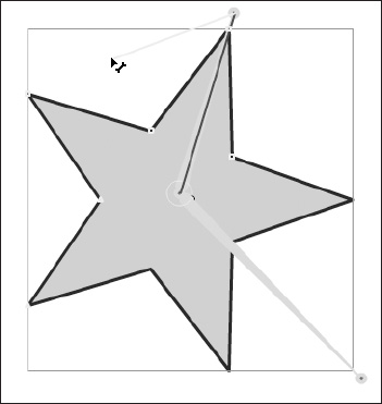
Figure 7-25. The Bind towol is used to apply multiple control points to bones.
With the Bind tool, you can link other control points in the shape, which are not highlighted yellow, to a particular bone. There are two ways to add a control point to a bone:
- With the
Bindtool selected, Shift-click any control point that is not highlighted yellow. As shown in Figure 7-25, you may also Shift-drag from the child, or tail end, of any given bone. - In contrast, if you would like to remove control points from bones, you may use the Ctrl key (Cmd key on a Mac) instead of Shift. Using the Ctrl key, you may either click or drag to remove unwanted control points.
Finally, you may have noticed that some control points are squares and some control points are triangular. This small difference is an indicator for how many bones are connected to that particular control point. As we mentioned earlier, you have the option to link multiple bones to a single control point. The square signifies that this particular control point is connected to one bone. Consequently, a triangle lets the designer know that this control point is governed by two or more bones.
For great practice working with the Bind tool, try to bind the IK armature from ch07_human_star.fla that was discussed earlier. This file is found in the sample files directory for this chapter.
Summary
Well, you learned some pretty cool things in this chapter. And, we really only scratched the surface of the new and powerful capabilities now available through the use of the Flash IK tools. We trust that your creative interests have been stirred and hope you already have many uses for this newly acquired knowledge.
In this chapter we discussed
- Inverse kinematics
- Using the
Bonetool to apply an IK system - Animating complex systems and characters with IK
- Applying IK to vector shapes with the
BoneandBindtools