
18
GHIDRA PROCESSORS

Processor modules, the most complex of Ghidra’s module types, are responsible for all of the disassembly operations that take place within Ghidra. Beyond the obvious conversion of machine language opcodes into their assembly language equivalents, processor modules also support the creation of functions, cross-references, and stack frames.
While the number of processors supported by Ghidra is impressive and increases with every major release, development of a new Ghidra processor module is required in some circumstances. The obvious case for developing a processor module is reverse engineering a binary for which no processor module exists in Ghidra. Among other things, such a binary might represent a firmware image for an embedded microcontroller or an executable image pulled from handheld or Internet of Things (IoT) devices. A less-obvious use for a processor module is to disassemble the instructions of a custom virtual machine embedded within an obfuscated x86 executable. In such cases, the existing Ghidra x86 processor module would help you understand only the virtual machine itself, not the virtual machine’s underlying byte code.
Should you undertake this arduous task, we want to be sure you have a strong foothold to help support you in this endeavor. Each of our previous module examples (analyzer and loader) required modifying a single Java file. If you created these modules within the Eclipse GhidraDev environment, you were given a module template and task tags within each template to help you complete your task. Processor modules are more complex, and relationships between different files must be maintained for the processor module to work correctly. While we will not build a processor module from scratch in this chapter, we will provide you with a solid foundation to help you understand Ghidra processor modules and demonstrate creating and modifying components within those modules.
WHO IS LIKELY TO AUGMENT GHIDRA?
Based on a thoroughly unscientific study, we strongly suspect that the following categories exist:
Category 1 A small percentage of people who use Ghidra will modify or write a script to customize or automate some functionality related to Ghidra.
Category 2 Of the people in Category 1, a small percentage will choose to modify or develop a plugin to customize some functionality related to Ghidra.
Category 3 Of the people in Category 2, an even smaller percentage will choose to modify or write an analyzer to extend Ghidra’s analysis capabilities.
Category 4 Of the people in Category 3, a small percentage will choose to modify or write a loader for a new file format.
Category 5 A very small percentage of the people in Category 4 will choose to modify or write a Ghidra processor module because the number of instruction sets that require decoding is much smaller than the number of file formats that make use of those instruction sets. Thus, the demand for new processor modules is comparatively low.
As you get deeper into the list of categories, the nature of the associated tasks tends to become more and more specialized. However, just because you don’t currently envision yourself authoring a Ghidra processor module doesn’t mean there isn’t some utility in learning how they are built. Processor modules form the foundation on which Ghidra’s disassembly, assembly, and decompilation capabilities are built, and having some insight into their inner workings just might elevate you to Ghidra wizard status in the eyes of your colleagues.
Understanding Ghidra Processor Modules
Creating a processor module for a real-world architecture is a highly specialized, time-consuming effort and is beyond the scope of this book. However, some fundamental understanding of how processors and their associated instruction sets are represented in Ghidra will help you identify where to look so that you have the right resources at your fingertips when you need information about a Ghidra processor module.
Eclipse Processor Modules
We will start in somewhat familiar territory. When you use Eclipse ▸ GhidraDev to create a processor module, the resulting folder structure is basically the same as every other module type, but a processor module does not provide a Java source file, complete with comments, task tags, and a TODO list, in the src/main/java folder, as seen in Figure 18-1.
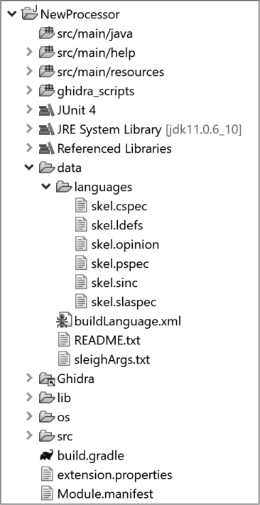
Figure 18-1: Processor module contents
Instead, the data folder (expanded in the figure) contains a lot more than the brief README.txt provided in the data folder for other module types. Let’s briefly meet the nine files contained in the data folder with a focus on their file extensions. (The skel prefix lets us know we are working with a skeleton.)
skel.cspec This is an XML-formatted, initially overwhelming compiler specification file.
skel.ldefs This is an XML-formatted language definition file. The skeleton has a commented-out template for defining a language.
skel.opinion This is an XML-formatted importer opinion file. The skeleton has a commented-out template for defining a language/compiler specification.
skel.pspec This is an XML-formatted processor specification file.
skel.sinc This is generally a SLEIGH file for language instructions.1
skel.slaspec This is a SLEIGH specification file.
buildLanguage.xml This XML file describes the build process for the files in the data/languages directory.
README.txt This file is the same in all of the modules, but within this module it finally makes sense as it focuses on the contents of the data/ directory.
sleighArgs.txt This file holds SLEIGH compiler options.
The .ldefs and .opinion files were used in Chapter 17 when building your ELF shellcode loader. Other file extensions will be seen in context as you work through examples. You will learn how to work with these files to modify a processor module, but first let’s discuss a new term specific to processor modules—SLEIGH.
SLEIGH
SLEIGH is a language specific to Ghidra that describes microprocessor instruction sets to support the Ghidra disassembly and decompilation processes.2 Files within the languages directory (see Figure 18-1) are either written in SLEIGH or presented in XML format, so you will definitely need to learn a little about SLEIGH to create or modify a processor module.
The specification of how instructions are encoded and how they are interpreted by a processor is contained in a .slaspec file (somewhat analogous to the role of a .c file). When a processor family has a number of distinct variants, each variant may have its own .slaspec file, while common behaviors across variants may be factored out into separate .sinc files (similar to the role of .h files), which may be included in many .slaspec files. Ghidra’s ARM processor is an excellent example of this, with over a dozen .slaspec files, each referencing one or more of five .sinc files. These files constitute the SLEIGH source code for a processor module, and it is the SLEIGH compiler’s job to compile them into a .sla file suitable for use by Ghidra.
Rather than taking a deep dive into SLEIGH from a theoretical perspective, we will introduce various components of the SLEIGH language as we encounter and require them in our examples, but first let’s look at the sort of information that a SLEIGH file contains about instructions.
To see additional information associated with an instruction in a CodeBrowser listing, right-click and select Instruction Info from the context menu. The displayed information is derived from SLEIGH file specifications for the selected instruction. Figure 18-2 shows the Instruction Info window for an x86-64 PUSH instruction.

Figure 18-2: Instruction Info window for x86-64 PUSH instruction
The Instruction Info window combines information about the PUSH instruction from the SLEIGH file with details about the specific use of PUSH at address 00100736. Later in the chapter, we will work with instruction definitions within a SLEIGH file and will revisit this window in the context of the instructions we are working with.
Processor Manuals
The documentation provided by the manufacturer of a processor is an important resource for obtaining information about the instruction set. While these copyrighted materials cannot be included within your Ghidra distribution, you can easily incorporate them through a right-click context menu option in the Listing window. If you right-click any instruction and select Processor Manual, you are likely to see a message similar to that shown in Figure 18-3, informing you that the manual for the current processor is not available in the expected location.
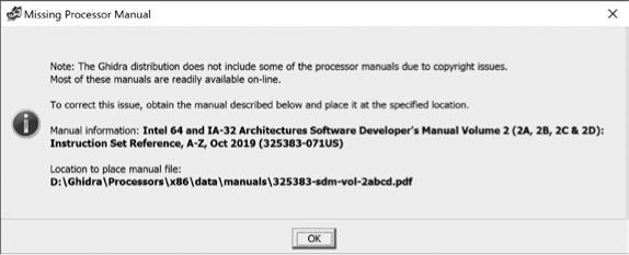
Figure 18-3: Missing Processor Manual dialog
Here, Ghidra provides you the information needed to resolve the missing manual situation. In this particular example, you first need to locate the x86 manual online and then save it with the specified name and location.
NOTE
There are many processor manuals associated with the x86. Find the correct manual online by searching for the identifier provided at the end of the manual information: 325383-060US.
Once you have a manual properly installed, selecting Processor Manual will display the manual. Since processor manuals tend to be large (this particular manual for the x86 processor weighs in at almost 2,200 pages), Ghidra helpfully includes the capability to process index files that map an instruction to a specific page in a manual. Fortunately, the index for this specific x86 manual has already been created for you.
Processor manuals should be placed in the Ghidra/Processors/<proc>/data/manuals directory appropriate for your processor. Index files should reside in the same directory as their associated manual. The format of an index file is relatively straightforward. The first few lines of Ghidra’s x86.idx file are shown in the following listing:
@Intel64_IA32_SoftwareDevelopersManual.pdf [Intel 64 and IA-32 Architectures
Software Developer's Manual Volume 2 (2A, 2B, 2C & 2D): Instruction Set
Reference, A-Z, Sep 2016 (325383-060US)]
AAA, 120
AAD, 122
BLENDPS, 123
AAM, 124
The first line in the file (which has been wrapped across three lines in this listing) pairs the manual’s local filename with descriptive text displayed to the user when the manual is not present on the system. The format of the line is as follows:
@FilenameInGhidraManualDirectory [Description of manual file]
Each additional line is of the form INSTRUCTION, page. The instruction must be uppercase, and the page number is counted from the first page of the .pdf file. (This is not necessarily the page number that appears on any given page of the document.)
Several manuals can be referenced in a single .idx file. Simply use additional @ directives to delineate each additional manual’s instruction map. More information about processor manual index files may be found in docs/languages/manual_index.txt in your Ghidra installation directory.
Once you have a manual saved and indexed, selecting Processor Manual for any instruction in the Listing window should take you to its corresponding page within the manual. If the manual does not appear, you may need to choose Edit ▸ Tools Options ▸ Processor Manuals to configure an appropriate viewer application for your manual. A sample viewer setting to open the manual using Firefox is shown in Figure 18-4.

Figure 18-4: Processor Manuals tool options
Now that you have some basic processor module terminology under your belt, it’s time to dive into the internals of a processor module implementation.
Modifying a Ghidra Processor Module
Building a processor module from scratch is a significant undertaking. Rather than jumping in headfirst, we are going to start, as we did in in previous examples, by modifying an existing module. Since we want to demonstrate concepts related to real-world problems, we will start by identifying a hypothetical issue regarding Ghidra’s x86 processor module. We will walk through some examples that address the issue and then use what we have learned to create a big picture view of how all of the various components work together to form a complete Ghidra processor module.
GHIDRA’S SLEIGH EDITOR
To assist you in modifying and building processor modules, Ghidra includes a SLEIGH editor that easily integrates into the Eclipse environment. The installation instructions for the editor are part of the SLEIGH readme file referenced in the preceding section and take only a few steps. Special functionality that the editor supports includes the following:
Syntax highlight Colorizes content that has special meaning (for example, comments, tokens, strings, variables, and so on).
Validation Marks many syntax errors and generates warnings for errors that would otherwise remain undetected until compilation.
QuickFix Provides recommendations for resolving issues detected by the editor. (This is similar to the QuickFix options for import statements we saw in Chapter 15.)
Hover Provides additional information for many constructs when you hover over the construct.
Navigation Provides navigation functionality specific to SLEIGH (for example, subconstructors, tokens, registers, pcodeops, and so on).
Find references Quickly finds all uses of a variable.
Renaming Rather than traditional string-based search and replace, this renames an actual variable in the file and other related .sinc and .slaspec files.
Code formatting Reformats files specific to the structure of the SLEIGH language (for example, lines up constructors based on keywords, lines up entries within attach, and so on). This functionality can be applied to an entire file or a selected section.
While we recommend using this editor, especially for the helpful early syntax checking, the development of our examples in this chapter are not specific to this editor.
Problem Statement
A quick search of the Ghidra/Processors directory in your local installation shows that the x86 processor module includes many instructions but appears to be missing a hypothetical virtual machine extension (VMX) management instruction for the IA32 and IA64 architectures.3 This instruction (which we just invented for this example) is called VMXPLODE. Its behavior is similar to the VMXOFF instruction, which Ghidra does support. While the existing VMXOFF instruction causes the processor to leave VMX operation, VMXPLODE leaves with a flourish! We will walk you through adding this very important instruction to the existing Ghidra x86 processor module in order to introduce some of the concepts associated with building and modifying a processor module.
Example 1: Adding an Instruction to a Processor Module
Our first goal is to locate the files we need to modify to support the VMXPLODE instruction. The Ghidra/Processors directory contains subdirectories for all processors supported by Ghidra, one of which is the x86. You can open the x86 processor module (or any other processor module) directly in Eclipse using File ▸ Open Projects from File System or Archive and providing the path to the processor folder (Ghidra/Processors/x86). This will link your Eclipse instance to Ghidra’s x86 processor module, meaning that changes you make within Eclipse will be directly reflected in your Ghidra processor module.
A partially expanded version of the x86 module in Eclipse, which exactly reflects the associated Ghidra directory structure, is shown in Figure 18-5. The processor manual you downloaded is present along with the x86 index file.

Figure 18-5: x86 processor module in Eclipse Package Explorer
The x86 folder contains a data folder, like the one you saw in the processor module we created using Eclipse ▸ GhidraDev. Within this folder is the languages folder, which contains over 40 files, including 19 .sinc files that define language instructions. Because the x86 instruction set is rather large, the instruction set is broken up into files grouping similar instructions. Instead of creating a new .sinc file for our instruction, we’ll add it to an existing x86 .sinc file. If we were adding a new group of instructions to Ghidra (for example, the x86 SGX instruction set), we might create a new .sinc file to group them all together. (In fact, the SGX instructions are grouped in a common file called sgx.sinc. That accounts for one of the many .sinc files!)
By searching the .sinc files, we find that ia.sinc contains the definitions of the existing VMX instruction set. We’ll use the definition of VMXOFF in ia.sinc as a model to define VMXPLODE. VMXOFF is referenced in two different sections within ia.sinc. The first section is the definitions for the Intel IA hardware-assisted virtualization instructions:
# MFL: definitions for Intel IA hardware assisted virtualization instructions
define pcodeop invept; # Invalidate Translations Derived from extended page
# tables (EPT); opcode 66 0f 38 80
# -----CONTENT OMITTED HERE-----
define pcodeop vmread; # Read field from virtual-machine control structure;
# opcode 0f 78
define pcodeop vmwrite; # Write field to virtual-machine control structure;
# opcode 0f 79
define pcodeop vmxoff; # Leave VMX operation; opcode 0f 01 c4
define pcodeop vmxon; # Enter VMX operation; opcode f3 0f C7 /6
Each entry in the definitions section defines a pcodeop, which is a new microcode operation for the x86 architecture.
The definition includes a name and, in this case, a comment that includes a description and an opcode. We will need to populate the comment for our new command. A quick, alt-reality, web search (with a side of testing) confirms that the opcode 0f 01 c5 has long been reserved for VMXPLODE. We now have the information necessary to add our new instruction to the file. The following shows our new definition in context:
define pcodeop vmxoff; # Leave VMX operation; opcode 0f 01 c4
define pcodeop vmxplode; # Explode (Fake) VMX operation; opcode 0f 01 c5
define pcodeop vmxon; # Enter VMX operation; opcode f3 0f C7 /6
The second location we encounter VMXOFF within ia.sinc (and where we will insert our new instruction) is the opcode definition section. (We omitted part of this content for clarity and wrapped some instruction definition lines for readability.) While we won’t completely dissect the 8,000+ lines of code in the ia.sinc file, there are several interesting points to make regarding the following listing:
# Intel hardware assisted virtualization opcodes
# -----CONTENT OMITTED HERE-----
# TODO: invokes a VM function specified in EAX➊
:VMFUNC EAX is vexMode=0 & byte=0x0f; byte=0x01; byte=0xd4 & EAX { vmfunc(EAX); }
# TODO: this launches the VM managed by the current VMCS. How is the
# VMCS expressed for the emulator? For Ghidra analysis?
:VMLAUNCH is vexMode=0 & byte=0x0f; byte=0x01; byte=0xc2 { vmlaunch(); }
# TODO: this resumes the VM managed by the current VMCS. How is the
# VMCS expressed for the emulator? For Ghidra analysis?
:VMRESUME is vexMode=0 & byte=0x0f; byte=0x01; byte=0xc3 { vmresume(); }
# -----CONTENT OMITTED HERE-----
:VMWRITE Reg32, rm32 is vexMode=0 & opsize=1 & byte=0x0f; byte=0x79;➋
rm32 & Reg32 ... & check_Reg32_dest ... { vmwrite(rm32,Reg32); build check_Reg32_dest; }
@ifdef IA64➌
:VMWRITE Reg64, rm64 is vexMode=0 & opsize=2 & byte=0x0f; byte=0x79;
rm64 & Reg64 ... { vmwrite(rm64,Reg64); }
@endif
:VMXOFF is vexMode=0 & byte=0x0f; byte=0x01; byte=0xc4 { vmxoff(); }➍
:VMXPLODE is vexMode=0 & byte=0x0f; byte=0x01; byte=0xc5 { vmxplode(); }➎
# -----CONTENT OMITTED HERE-----
#END of changes for VMX opcodes
TODO comments ➊, found in many Ghidra files, identify tasks that have yet to be done. Searching for TODO tasks in Ghidra files is a great way to identify opportunities to contribute to this open source project.
Next, we see the VMWRITE instruction for 32-bit ➋ and 64-bit architectures. The 64-bit instruction is surrounded by a test ➌ to ensure it is included in only the 64-bit .sla file. While 32-bit instructions are valid in a 64-bit world (for example, EAX is the 32 least-significant bits of RAX), the converse is not true. The conditional statement ensures that instructions that operate on 64-bit registers are included for only 64-bit builds.
The VMXOFF instruction ➍ doesn’t directly involve registers, so there is no need to distinguish between 32- and 64-bit versions of the instruction. The constructor for our new instruction, VMXPLODE ➎, complete with its new opcode, is very similar to the constructor for VMXOFF. Let’s break this into the components that make up the line:
:VMXPLODE
This is the instruction being defined and is displayed in the disassembly listing.
is vexMode=0 & byte=0x0f; byte=0x01; byte=0xc5
These are the bit patterns associated with the instruction and provide a constraint for the instruction. The & represents a logical AND operation. The semicolons serve a dual purpose of concatenation and logical AND. This part says, “If we are not in VEX mode and the opcode is these 3 bytes in this order, then this constraint is met.”4
{ vmxplode(); }
Curly brackets enclose the semantic actions section of an instruction. The SLEIGH compiler translates these actions into an internal Ghidra form known as p-code (discussed later in this chapter). Defining an instruction requires understanding SLEIGH operators and syntax. This portion of the constructor, where the real work associated with most instructions is done, can quickly become a complex sequence of multiple statements separated by semicolons. In this case, since we have defined VMXPLODE as a new p-code operation (define pcodeop vmxplode;), we can invoke the instruction here. In future examples, we will add additional SLEIGH semantic actions to this section.
The largest x86 .sinc file is ia.sinc because a lot of instructions are defined within this file (including our new VMXPLODE instruction) and a significant amount of content to define the attributes of the x86 processor (for example, endianness, registers, contexts, tokens, variables, and so on). Much of this x86-specific content within ia.sinc is not replicated in the other .sinc files in this directory, since all the .sinc files are, in turn, included in a SLEIGH specification (.slaspec) file.
The two .slaspec files for x86, x86.slaspec and x86-64.slaspec, each contain include statements for the required .sinc files. (Note that you could forego the use of .sinc files and directly include the content in the .slaspec file, which might make sense for a processor with a small instruction set.) The contents of x86-64.slaspec are shown in the following listing:
@define IA64 "IA64" # Only in x86-64.slaspec
➊ @include "ia.sinc"
@include "avx.sinc"
@include "avx_manual.sinc"
@include "avx2.sinc"
@include "avx2_manual.sinc"
@include "rdrand.sinc" # Only in x86-64.slaspec
@include "rdseed.sinc" # Only in x86-64.slaspec
@include "sgx.sinc" # Only in x86-64.slaspec
@include "adx.sinc"
@include "clwb.sinc"
@include "pclmulqdq.sinc"
@include "mpx.sinc"
@include "lzcnt.sinc"
@include "bmi1.sinc"
@include "bmi2.sinc"
@include "sha.sinc"
@include "smx.sinc"
@include "cet.sinc"
@include "fma.sinc" # Only in x86-64.slaspec
We have added EOL comments to denote the content that is unique to the x86-64.slaspec file. (The x86.slaspec file is a subset of the x86-64.slaspec file.) Among the included files is ia.sinc ➊, in which we defined VMXPLODE, so we don’t need to add anything. If you create a new .sinc file, you need to add an include statement in both x86.slaspec and x86-64.slaspec in order for the instruction to be recognized in both 32- and 64-bit binaries.
To test if Ghidra can recognize the new instruction when it is used in a binary, we construct a test file. The file will first verify that the VMXOFF instruction is still recognized and then verify that VMXPLODE has been added successfully. The C source file for testing VMXOFF contains the following:
#include <stdio.h>
// The following function declares an assembly block and tells the
// compiler that it should execute the code without moving or changing it.
void do_vmx(int v) {
asm volatile (
"vmxon %0;" // Enable hypervisor operation
"vmxoff;" // Disable hypervisor operation
"nop;" // Tiny nop slide to accommodate examples
"nop;"
"nop;"
"nop;"
"nop;"
"nop;"
"nop;"
"vmxoff;" // Disable hypervisor operation
:
:"m"(v) // Holds the input variable
:
);
}
int main() {
int x;
printf("Enter an int: ");
scanf("%d", &x);
printf("After input, x=%d
", x);
do_vmx(x);
printf("After do_vmx, x=%d
", x);
return 0;
}
When we load the compiled binary into Ghidra, we see the following body of the function do_vmx in the Listing window:
0010071a 55 PUSH RBP
0010071b 48 89 e5 MOV RBP,RSP
0010071e 89 7d fc MOV dword ptr [RBP + local_c],EDI
00100721 f3 0f c7 VMXON qword ptr [RBP + local_c]
75 fc
➊ 00100726 0f 01 c4 VMXOFF
00100729 90 NOP
0010072a 90 NOP
0010072b 90 NOP
0010072c 90 NOP
0010072d 90 NOP
0010072e 90 NOP
0010072f 90 NOP
➋ 00100730 0f 01 c4 VMXOFF
00100733 90 NOP
00100734 5d POP RBP
00100735 c3 RET
The bytes displayed for the opcode (0f 01 c4) in the two calls to VMXOFF ➊➋ match the opcode we observed in ia.sinc for this command. The following listing from the Decompiler window is consistent with what we know about the source code and the associated disassembly:
void do_vmx(undefined4 param_1)
{
undefined4 unaff_EBP;
vmxon(CONCAT44(unaff_EBP,param_1));
vmxoff();
vmxoff();
return;
}
To test that Ghidra detects the VMXPLODE instruction, we replace the first occurrence of VMXOFF in the do_vmx test function with VMXPLODE. However, the VMXPLODE instruction is missing not only from Ghidra’s processor definition, but also from our compiler’s knowledge base. In order for the assembler to accept our code, we hand-assembled the instruction using a data declaration instead of using the instruction mnemonic directly so that the assembler can process the new instruction:
//"vmxoff;" // replace this line
".byte 0x0f, 0x01, 0xc5;" // with this hand assembled one
When you load your updated binary into Ghidra, you see the following in the Listing window:
0010071a 55 PUSH RBP
0010071b 48 89 e5 MOV RBP,RSP
0010071e 89 7d fc MOV dword ptr [RBP + local_c],EDI
00100721 f3 0f c7 VMXON qword ptr [RBP + local_c]
75 fc
➊ 00100726 0f 01 c5 VMXPLODE
00100729 90 NOP
0010072a 90 NOP
0010072b 90 NOP
0010072c 90 NOP
0010072d 90 NOP
0010072e 90 NOP
0010072f 90 NOP
00100730 0f 01 c4 VMXOFF
00100733 90 NOP
00100734 5d POP RBP
00100735 c3 RET
Your new instruction ➊ appears along with the opcode (0f 01 c5) that we have assigned to it. The Decompiler window also shows the new instruction:
void do_vmx(undefined4 param_1)
{
undefined4 unaff_EBP;
vmxon(CONCAT44(unaff_EBP,param_1));
vmxplode();
vmxoff();
return;
}
So, what work has Ghidra undertaken in the background to add our new instruction to its x86 processor instruction set? When Ghidra is restarted (as it needs to be for these changes to take effect), it detects that the underlying .sinc file changed and generates a new .sla file when one is needed.
In this example, when we were loading the original compiled 64-bit binary file, Ghidra detected the change in the ia.sinc file and displayed the window shown in Figure 18-6 while it was recompiling the ia.sinc file. (Note that it recompiles only when needed, not automatically on restart.) Because we loaded a 64-bit file, only x86-64.sla was updated, and not x86.sla. Later, when we loaded the updated file, complete with the VMXPLODE command, Ghidra did not recompile, as no changes were made to any underlying SLEIGH source files since the previous load.
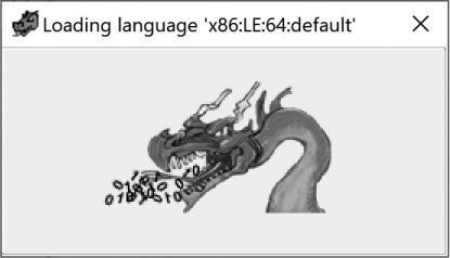
Figure 18-6: Ghidra window displayed while recompiling a language file
Here is a summary of the steps to add a new instruction to a processor module:
Locate the languages directory for the target processor (for example, Ghidra/Processor/<<targetprocessor>>/data/languages).
Add the instruction to a selected processor .sinc file, or create a new .sinc file (for example, Ghidra/Processor/<targetprocessor>/data/languages/<targetprocessor>.sinc).
If you created a new .sinc file, make sure it is included in the .slaspec file (for example, Ghidra/Processor/<targetprocessor>/data/languages/<targetprocessor>.slaspec).
Example 2: Modifying an Instruction in a Processor Module
We have now successfully added an instruction to the Ghidra x86 processor module, but we have not yet accomplished our goal of making VMXPLODE leave with a flourish. Currently, it just exits without any excitement whatsoever. While it is challenging to make an assembly language instruction do anything that would qualify as a flourish, we can make our instruction dab when it exits.5 In this example, we will step through three options for making VMXPLODE dab for us. For our first option, we will exit after setting EAX to a hardcoded value: 0xDAB.
Option 1: Set EAX to a Constant Value
Having the VMXPLODE instruction set the value of EAX to 0xDAB prior to exiting requires only a minor modification to one instruction in the same file (ia.sinc) that we worked with in Example 1. The following listing shows the VMXOFF and VMXPLODE instructions as we left them after Example 1:
:VMXOFF is vexMode=0 & byte=0x0f; byte=0x01; byte=0xc4 { vmxoff(); }
:VMXPLODE is vexMode=0 & byte=0x0f; byte=0x01; byte=0xc5 { vmxplode(); }
Within the instruction contents, add the assignment to EAX immediately before the vmxplode action, as shown in the following listing:
:VMXOFF is vexMode=0 & byte=0x0f; byte=0x01; byte=0xc4 { vmxoff(); }
:VMXPLODE is vexMode=0 & byte=0x0f; byte=0x01; byte=0xc5 { EAX=0xDAB; vmxplode(); }
When we reopen Ghidra and load our test file, Ghidra once again displays the window shown in Figure 18-6 to let us know that it has detected a change in an associated language file and is regenerating x86-64.sla. The Listing window doesn’t show any changes after Ghidra auto analyzes the file, but the difference is apparent in the Decompiler window:
undefined4 do_vmx(undefined4 param_1)
{
undefined4 unaff_EBP;
vmxon(CONCAT44(unaff_EBP,param_1));
vmxplode();
vmxoff();
return 0xdab;
}
In the Decompiler window, the return statement now returns the contents of EAX (0xDAB). This is interesting because we know this is a void function and doesn’t have a return value. The Listing window entry for the new instruction doesn’t show that the VMXPLODE command has changed in any way:
00100726 0f 01 c5 VMXPLODE
An important distinction between decompilers and disassemblers is that decompilers understand and incorporate the full semantic behavior of each instruction as part of their analysis, while disassemblers are focused largely on the proper syntactic representation of each instruction. In this example, VMXPLODE takes no operands and is correctly displayed by the disassembler, providing no visual cue that EAX has changed. When reading a disassembly, it is entirely your responsibility to understand the semantic behavior of each instruction. This example also demonstrates the value of the decompiler, which, understanding the full semantics of VMXPLODE, is able to recognize that EAX is changed as a side effect of the instruction. The decompiler also recognizes that EAX is not used for the remainder of the function and assumes that the value is intended to be returned to the calling function.
Ghidra offers you the opportunity to dive a little deeper into how instructions work and allows you to detect and test subtle differences in instructions like this one. First, let’s look at the some of the instruction information associated with VMXPLODE, shown in Figure 18-7.
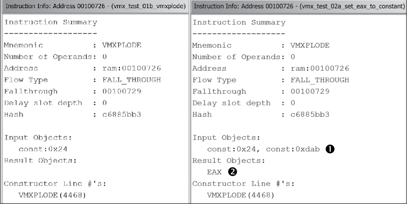
Figure 18-7: VMXPLODE instruction info
On the left is our original VMXPLODE instruction, and on the right is the modified version, with 0xdab listed in the Input Objects ➊ section and EAX under Result Objects ➋. We can obtain additional insight about any instruction by looking at underlying information, called p-code, that we haven’t looked at previously.6 The p-code associated with an instruction can be very informative about what exactly an instruction does.
P-CODE: HOW LOW CAN YOU GO?
The Ghidra documentation describes p-code as a “register transfer language designed for reverse engineering applications.” A register transfer language (RTL) is an architecture-independent, assembly-language-like language often used as an intermediate representation (IR, or IL for intermediate language) between a high-level language such as C and a target assembly language such as x86 or ARM. Compilers are often composed of a language-specific frontend that translates source code into an IR, and an architecture-specific backend that translates IR into a specific assembly language. This modularity allows a C frontend to be combined with an x86 backend to create a C compiler that produces x86 code and offers the flexibility to replace the backend with an ARM module to instantly have a C compiler that generates ARM code. Swap out the C frontend for a FORTRAN frontend and now you have a FORTRAN compiler for ARM.
Working at the IR level allows us to build tools that operate on our IR rather than maintaining a set of C-specific or ARM-specific tools that are useless to us with other languages or architectures. For example, once we have an optimizer that operates on IR, we can reuse that optimizer with any of our frontend/backend combinations without rewriting the optimizer in each case.
A reverse engineering toolchain, not unsurprisingly, runs in the opposite direction of a traditional software build chain. An RE frontend needs to translate machine code to IR (a process often called lifting), while an RE backend translates IR to a high-level language such as C. A pure disassembler doesn’t qualify as a frontend under this definition as it gets us only from machine code to assembly language. Ghidra’s decompiler is an IR-to-C backend. Ghidra processor modules are machine-code-to-IR frontends.
When you build or modify a Ghidra processor module in SLEIGH, one of the first things you do is let the SLEIGH compiler know about any new p-code operations that you need to introduce in order to describe the semantic actions of any new or modified instructions. For example, the operation definition
define pcodeop vmxplode
that we added to our ia.sinc file instructs the SLEIGH compiler that vmxplode is a valid semantic action available for describing the behavior of any instruction in our architecture. One of the most difficult challenges that you will face is describing each new or changed instruction using a sequence of syntactically correct SLEIGH statements that correctly describe the actions associated with the instruction. All of this information is captured in the .slaspec and included .sinc files that make up your processor. If you do a good enough job, Ghidra will hand you the decompiler backend for free.
To view the p-code within the Listing window, open the Browser Field Formatter and choose the Instruction/Data tab, right-click the P-code bar, and enable the field. Once the Listing window displays the p-code associated with each instruction, we can compare the previous two listings to observe any differences. With p-code enabled, our first implementation of VMXPLODE appears as follows with the p-code displayed after each instruction:
0010071b 48 89 e5 MOV RBP,RSP
RBP = COPY RSP
$U620:8 = INT_ADD RBP, -4:8
$U1fd0:4 = COPY EDI
STORE ram($U620), $U1fd0
00100721 f3 0f c7 75 fc VMXON qword ptr [RBP + local_c]
$U620:8 = INT_ADD RBP, -4:8
$Ua50:8 = LOAD ram($U620)
CALLOTHER "vmxon", $Ua50
00100726 0f 01 c5 VMXPLODE
CALLOTHER "vmxplode"
00100729 90 NOP
And here is the modified VMXPLODE:
00100726 0f 01 c5 VMXPLODE
➊ EAX = COPY 0xdab:4
CALLOTHER "vmxplode"
The associated p-code now shows the constant value (0xdab) being moved into EAX ➊.
Option 2: Set a Register (Determined by an Operand) to a Constant Value
Instruction sets are typically made up of a mix of instructions that operate on zero or more operands. As the number and types of operands associated with an instruction increase, so does the level of difficulty in describing the instruction’s semantics. In this example, we’ll extend the behavior of VMXPLODE to require a single register operand, which will be made to dab. This will require us to visit sections of the ia.sinc file that we have not previously encountered. This time, let’s start with a modified version of the instruction and then work backward. The following listing shows the modifications we need to make to our instruction definition to accept an operand that will identify the register that ultimately will hold 0xDAB:
:VMXPLODE Reg32➊ is vexMode=0 & byte=0x0f; byte=0x01; byte=0xc5; Reg32➋
{ Reg32=0xDAB➋; vmxplode(); }
Here, Reg32 ➊ is declared as a local identifier and then concatenated with the opcode ➋ to become part of the constraints associated with the instruction. Rather than assigning 0xDAB directly into EAX as we did previously, the instruction now assigns the value into Reg32 ➌. To accomplish our goal, we will need to determine a way to associate the value in Reg32 with the x86 register of our choosing. Let’s investigate other components within ia.sinc to help us understand how to correctly map an operand to a specific x86 general-purpose register.
Near the start of ia.sinc, we see all of the definitions that will be needed by the entire specification, as shown in Listing 18-1.
# SLA specification file for Intel x86
@ifdef IA64➊
@define SIZE "8"
@define STACKPTR "RSP"
@else
@define SIZE "4"
@define STACKPTR "ESP"
@endif
define endian=little;➋
define space ram type=ram_space size=$(SIZE) default;
define space register type=register_space size=4;
# General purpose registers➌
@ifdef IA64
define register offset=0 size=8 [ RAX RCX RDX RBX RSP RBP RSI RDI ]➍;
define register offset=0 size=4 [ EAX _ ECX _ EDX _ EBX _ ESP _ EBP _ ESI _ EDI ];
define register offset=0 size=2 [ AX _ _ _ CX _ _ _ DX _ _ _ BX]; # truncated
define register offset=0 size=1 [ AL AH _ _ _ _ _ _ CL CH _ _ _ _ _ _]; # truncated y
define register offset=0x80 size=8 [ R8 R9 R10 R11 R12 R13 R14 R15 ]➎;
define register offset=0x80 size=4 [ R8D _ R9D _ R10D _ R11D _ R12D _ R13D _ R14D _ R15D ];
define register offset=0x80 size=2 [ R8W _ _ _ R9W _ _ _ R10W _ _ _ R11W ]; # truncated
define register offset=0x80 size=1 [ R8B _ _ _ _ _ _ _ R9B _ _ _ _ _ _ _ ]; # truncated
@else
define register offset=0 size=4 [ EAX ECX EDX EBX ESP EBP ESI EDI ];
define register offset=0 size=2 [ AX _ CX _ DX _ BX _ SP _ BP _ SI _ DI ];
define register offset=0 size=1 [ AL AH _ _ CL CH _ _ DL DH _ _ BL BH ];
@endif
Listing 18-1: Partial SLEIGH specification for x86 registers (adapted from ia.sinc)
At the top of the file, we see the name and size of the stack pointer for 32- and 64-bit builds ➊, as well as the endianness ➋ for the x86. A comment ➌ introduces the start of the definitions of the general-purpose registers. As with all its other components, SLEIGH has a special convention for naming and defining registers: registers reside in a special address space named register, and every register (which may span 1 or more bytes) is assigned an offset within the address space. A SLEIGH register definition indicates the offset at which a list of registers begins within the register address space. All registers in a register list are contiguous unless an underscore is used to create space between them. The address space layout of the 64-bit RAX and RCX registers ➍ is shown in more detail in Figure 18-8.
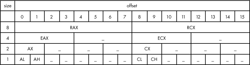
Figure 18-8: Register layout for x86-64 RAX and RCX registers
The register named AL occupies exactly the same location as the least significant byte of RAX, EAX, and AX (since x86 is a little-endian). Similarly, EAX occupies the low 4 bytes of RAX. An underscore indicates that no name is associated with a given range of bytes for the given size. In this case, there is no name for the 4-byte block at offsets four to seven, although these bytes are synonymous with the upper half of the RAX register. Listing 18-1 describes a separate block of registers beginning with R8 at offset 0x80 ➎. The 1-byte register at offset 0x80 is known as R8B, and the 1-byte register at offset 0x88 is known as R9B. Hopefully, the similarity between the textual register definition in Listing 18-1 and the tabular representation in Figure 18-8 are obvious, since the register definitions in a SLEIGH file are nothing more than the textual representation of an architecture’s register address space.
If you are writing a SLEIGH description of an architecture that is entirely unsupported by Ghidra, it will be your job to lay out the register address space for that architecture, ensuring no overlap between registers unless the architecture requires it (such as RAX, EAX, AX, AH, AL in the x86-64 architecture).
Now that you understand how registers are represented in SLEIGH, let’s return to our objective of choosing a register to dab! In order for our instruction to function properly, it needs to map the identifier Reg32 to a general-purpose register. To accomplish this task, we can use an existing definition in ia.sinc that is found within the following lines of code:
➊ define token modrm (8)
mod = (6,7)
reg_opcode = (3,5)
reg_opcode_hb = (5,5)
r_m = (0,2)
row = (4,7)
col = (0,2)
page = (3,3)
cond = (0,3)
reg8 = (3,5)
reg16 = (3,5)
➋ reg32 = (3,5)
reg64 = (3,5)
reg8_x0 = (3,5)
The define statement ➊ is declaring an 8-bit token called modrm. A SLEIGH token is a syntactic element used to represent byte-sized components that make up the instructions being modeled.7 SLEIGH allows the definition of any number of bitfields (a range of one or more contiguous bits) within a token. When you’re defining instructions in SLEIGH, these bitfields provide a convenient, symbolic means of specifying the associated operands. In this listing, a bitfield named reg32 ➋ spans bits 3 through 5 of modrm. This 3-bit field can take on the values 0 to 7 and can be used to choose one of the eight 32-bit x86 registers.
If we move to the next reference of reg32 in the file, we see the following interesting lines of code:
# attach variables fieldlist registerlist;
attach variables [ r32 reg32 base index ] [ EAX ECX EDX EBX ESP EBP ESI EDI ];
# 0 1 2 3 4 5 6 7
The first and last lines of the listing contain comments that show the SLEIGH syntax for this statement and the ordinal values for each register. The attach variables statement associates the field with a list (in this case, a list of the x86 general-purpose registers). A rough interpretation of the line of code, taking the preceding modrm definition into account, is the following: The value of reg32 is determined by looking at bits 3 to 5 of the token modrm. The resulting value (0 to 7) is then used as an index to select a register from the list.
We now have a way to identify the general-purpose registers to target for 0xDAB. Our next encounter with Reg32 within the file finds the following code, which contains the constructor for Reg32 for both 32- and 64-bit registers, and now we can see the association between reg32 and Reg32:8
Reg32: reg32 is rexRprefix=0 & reg32 { export reg32; } #64-bit Reg32
Reg32: reg32 is reg32 { export reg32; } #32-bit Reg32
Let’s return to the command that started this little adventure:
:VMXPLODE Reg32➊is vexMode=0 & byte=0x0f; byte=0x01; byte=0xc5; Reg32➋
{ Reg32=0xDAB; vmxplode(); }
We are going to include an operand with our call to VMXPLODE that will determine which register gets the value 0xDAB. We will update our test binary further by removing the first NOP and appending the value 0x08 to our hand-assembled instruction. The first 3 bytes are the opcode (0f 01 c5), and the following byte (08) will be the operand that specifies the register to use:
".byte 0x0f, 0x01, 0xc5, 0x08;" // hand assembled with operand
Figure 18-9 demonstrates the step-by-step translation from the operand through to the determination of the register based on the information in the ia.sinc file.

Figure 18-9: Translation path from operand to register
The original operand value, shown in the first row, is 0x08 ➊. The value is decoded into its binary ➋ form and overlaid with the fields of the modrm token ➌. Bits 3 to 5 are extracted, yielding the Reg32 value 001 ➍. This value is used to index the ordinal map ➎ to select the ECX register ➏. Therefore, the operand 0x08 specifies that ECX will get the value 0xDAB.
When we save the updated ia.sinc file, restart Ghidra, and then load and analyze the file, the following listing is generated, showing the use of our new instruction. As expected, ECX is the register selected to hold 0xDAB:
00100721 f3 0f c7 75 fc VMXON qword ptr [RBP + local_c]
$U620:8 = INT_ADD RBP, -4:8
$Ua50:8 = LOAD ram($U620)
CALLOTHER "vmxon", $Ua50
00100726 0f 01 c5 08 VMXPLODE ECX
ECX = COPY 0xdab:4
CALLOTHER "vmxplode"
0010072a 90 NOP
The value 0xDAB no longer appears in the Decompiler window because the decompiler assumes that the return value is in EAX. In this case, we are using ECX so the decompiler does not identify a return value.
Now that we can make a selected register dab, let’s add a 32-bit immediate value as a second operand. This will double our celebratory potential.
Option 3: The Register and Value Operands
To extend the syntax of our instruction to take two operands (a destination register and a source constant), update the definition of VMXPLODE as shown here:
:VMXPLODE Reg32,imm32 is vexMode=0 & byte=0x0f; byte=0x01; byte=0xc5;
Reg32; imm32 { Reg32=imm32; vmxplode(); }
The addition of an immediate 32-bit constant to the instruction requires 4 additional bytes to encode. Accordingly, we replace the next four NOPs with values that correctly encode our imm32 in little-endian order, as seen here:
".byte 0x0f, 0x01, 0xc5, 0x08, 0xb8, 0xdb, 0xee, 0x0f;"
"nop;"
"nop;"
When we reload the file, VMXPLODE exits with another flourish. As shown in the following listing (with p-code displayed), ECX now has the value 0xFEEDBB8 (which might be a more appealing exit flourish for science fiction fans):
00100726 0f 01 c5 VMXPLODE ECX,0xfeedbb8
08 b8 db
ee 0f
ECX = COPY 0xfeedbb8:4
CALLOTHER "vmxplode"
Example 3: Adding a Register to a Processor Module
We close out our processor module examples by extending an architecture with two entirely new registers.9 Recall the definition of the 32-bit general-purpose registers from earlier in the chapter:
define register offset=0 size=4 [EAX ECX EDX EBX ESP EBP ESI EDI];
The definition of a register requires an offset, a size, and the list of registers. We chose a starting offset into the registry memory address space after reviewing the currently allocated offsets and finding the space we need for two 4-byte registers. We can use this information to define two new 32-bit registers in the ia.sinc file called VMID and VMVER, as shown in the following listing:
# Define VMID and VMVER
define register offset=0x1500 size=4 [ VMID VMVER ];
Our instructions need a means to identify which new register (VMID or VMVER) they are operating on. In the previous example, we used a 3-bit field to select one of eight registers. To select between the two new registers requires only a single bit. The following statement defines a 1-bit field within the modrm token and associates the field with vmreg:
# Associate vmreg with a single bit in the modrm token.
vmreg = (3, 3)
The following statement attaches vmreg to the ordinal set containing the two registers, with 0 representing VMID and 1 representing VMVER:
attach variables [ vmreg ] [ VMID VMVER ];
Instruction definitions may refer to vmreg when any of the attached registers are valid within the instruction, while assembly language programmers may refer to VMID and VMER as operands in any instruction that allows a vmreg operand. Let’s compare the following two definitions of VMXPLODE. The first is from our previous example, where we chose the register from among the general-purpose registers, and the second selects one of our two registers rather than any of the general-purpose registers:
:VMXPLODE Reg32,imm32 is vexMode=0 & byte=0x0f; byte=0x01; byte=0xc5;
Reg32, imm32 { Reg32=imm32; vmxplode(); }
:VMXPLODE vmreg,imm32 is vexMode=0 & byte=0x0f; byte=0x01; byte=0xc5;
vmreg, imm32 { vmreg=imm32; vmxplode(); }
Reg32 is replaced with vmreg in the second listing. If we use the same input file with test instruction vmxplode 0x08,0xFEEDBB8, the immediate operand 0xFEEDBB8 will be loaded into VMVER, since the input value 0x08 maps to an ordinal value of 1 (because bit 3 is set), as we show in Figure 18-10, and VMVER is register 1 in vmreg. After loading the test file (after saving ia.sinc and restarting Ghidra), we see that the p-code in the Listing window shows that the immediate operand is loaded into VMVER:
00100726 0f 01 c5 VMXPLODE VMVER,0xfeedbb8
08 b8 db
ee 0f
VMVER = COPY 0xfeedbb8:4
CALLOTHER "vmxplode"
The associated instruction information, shown in Figure 18-10, confirms the change as well.
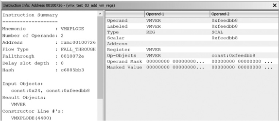
Figure 18-10: Instruction Info for VMXPLODE with new register VMVER selected
Summary
While we introduced only a small fraction of the x86 processor file contents in this chapter, we looked at the major components of a processor module, including instruction definitions, register definitions, and tokens, as well as how the Ghidra-specific language, SLEIGH, can be used to build, modify, and augment Ghidra processor modules. If you have a desire (or need) to add a new processor to Ghidra, we highly recommend looking at some of the more recent processors added to Ghidra. (The SuperH4.sinc file is particularly well-documented and the processor is significantly less complex than the x86 processor.)
We cannot emphasize enough the role that patience and experimentation play in any processor-development situation. The hard work more than pays off when you are able to reuse your processor module with each new binary you collect and potentially contribute the module back to the Ghidra project for the benefit of other reverse engineers.
In the next chapter, we take a deep dive into the functionality associated with the Ghidra Decompiler.