The LEGO MINDSTORMS EV3 set includes three types of sensors: Touch, Color, and Infrared. You can use these sensors to make your robot respond to its environment. For example, you can program your robot to make a sound when it sees you, avoid obstacles while driving, or follow colored lines. This part of the book will teach you how to create working robots that use these sensors.
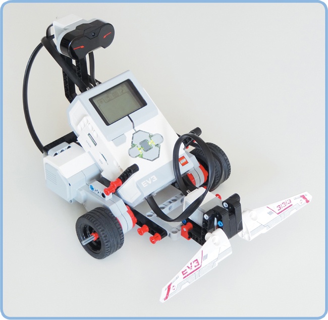
To learn how to work with sensors, we’ll expand the EXPLOR3R robot by adding a bumper that detects obstacles using the Touch Sensor, as shown in Figure 6-1. Once you have a handle on how to make programs that use the Touch Sensor, you’ll learn how to use the other sensors in subsequent chapters.
LEGO MINDSTORMS robots can’t actually see or feel the way humans do, but you can add sensors to them so they can collect and report information about their environment. By designing programs that can interpret this sensor information, you can make your robots seem intelligent by having them respond to their environment. For instance, you could create a program that makes the robot say “blue” when one of its sensors sees a piece of blue paper.
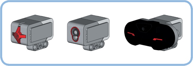
Your EV3 set contains three sensors that you can attach to your robot (see Figure 6-2) as well as some built-in sensors. The Touch Sensor detects whether the red button on the sensor is pressed or released. The Color Sensor detects the color of a surface and the intensity of a light source, as you’ll see in Chapter 7. The Infrared Sensor (covered in Chapter 8) measures the approximate distance to a nearby object, and it receives signals from the infrared remote.
In addition, each motor in the EV3 set has a built-in Rotation Sensor to measure the motor’s position and speed, and the EV3 brick can detect which of its Brick Buttons are pressed (see Chapter 9).
The Touch Sensor allows your robot to “feel” by detecting whether the red button on the sensor is currently pressed or released, as shown in Figure 6-3. The EV3 retrieves this information from the sensor and can use it in programs. For example, you could make your robot say “hello” whenever you press the Touch Sensor.

Despite its simplicity, the Touch Sensor is useful for many applications. For example, robots can use the Touch Sensor to detect obstacles in front of them. You can also use the Touch Sensor to detect that a mechanism in your robot has reached a certain position. In Chapter 18, for example, you’ll use the sensor to detect whether a robotic arm is lifted all the way.
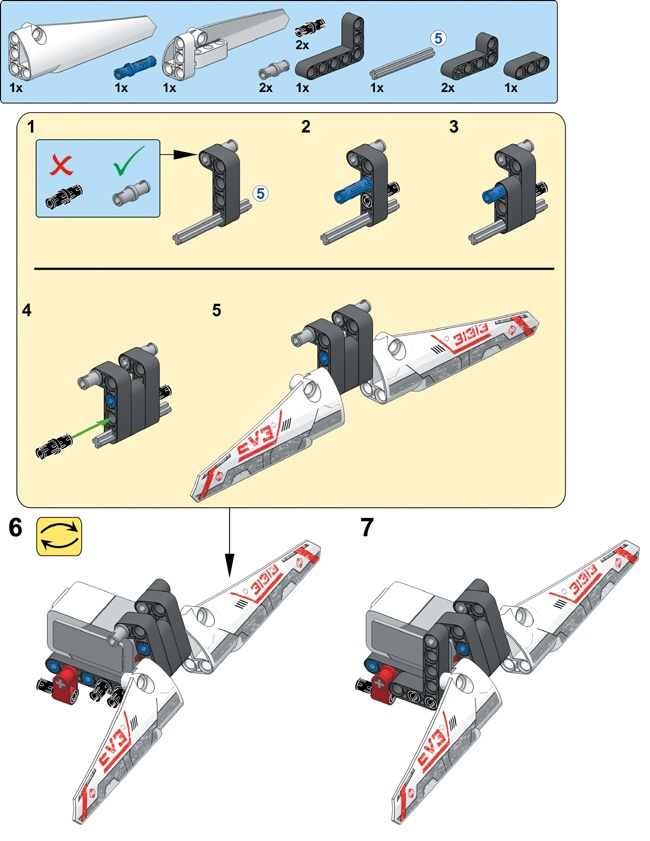
If you build a bumper and attach it to the Touch Sensor, then anytime the EXPLOR3R runs into an object with its bumper, the sensor will become pressed. The program on your EV3 can use this information to decide to move the robot in a different direction. Build the bumper and attach it to the robot as shown on the following pages. Be sure to connect the Touch Sensor to input port 1 using a short cable.


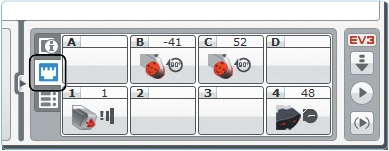
You can see the measurements reported by each sensor by opening the Port View application on the Brick Apps tab of your EV3 brick, as shown in Figure 6-4. For the Touch Sensor, a measurement of 1 means that it’s pressed, while 0 indicates that it’s released.

Figure 6-4. The Port View application on the Brick Apps tab. The EV3 brick automatically determines which sensors you’ve connected to the EV3 and displays their measurements on the screen. Use the buttons (Left, Right, Up, and Down) to see more details regarding each sensor.
You can use the buttons on the EV3 to navigate to measurements of the other sensors. At the bottom right of your screen (port 4), you should see the distance measurement of the Infrared Sensor (48% in this example). The two values at the top (–41 and 52) indicate the positions of the motors on ports B and C on your robot.
Some sensors can take more than one type of measurement. To see other measurements of the Infrared Sensor, for example, navigate to port 4, press the Center button, and choose a sensor mode. You’ll learn more about the meaning of each value as you read on.
If your robot is connected to the computer, you can also view sensor measurements on the Hardware Page in the EV3 software, as shown in Figure 6-5. Just use the method you find most convenient.
Now let’s look at how you can use these measurements in your programs. Let’s try using the Touch Sensor in a program that has the robot play a sound when the Touch Sensor is pressed.
Several programming blocks let you use sensors in your program, including the Wait, Loop, and Switch blocks. In this chapter, you’ll learn how each of these blocks work with the Touch Sensor, and the same principles apply to the other sensors in the EV3 set as well.
Earlier, you used a Wait block to pause the program for a set amount of time (say, five seconds). But you can also use a Wait block to pause a program until a sensor is triggered. For example, you can configure a Wait block to pause until the Touch Sensor is pressed by selecting the Touch Sensor mode, as shown in Figure 6-6.
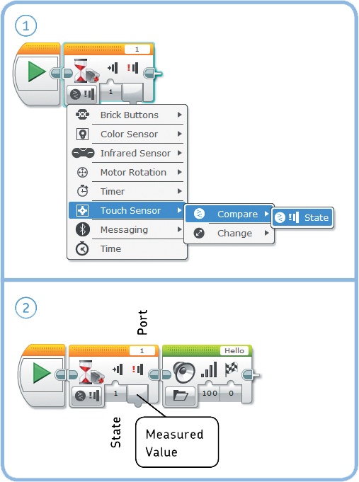
After selecting this mode, you must also choose between Compare and Change mode. In Compare mode, you specify with the State setting whether the program should wait until the sensor is released (0), pressed (1), or bumped (2). If you choose bumped, the program waits for a press followed by a release.
In Change mode, the program waits until the state of the sensor changes: If the sensor is pressed when the block begins running, the program waits until it’s released. If it’s released at first, the program pauses until the sensor is pressed.
The Port setting lets you specify which input port your sensor is connected to (in this case, port 1). Finally, the Measured Value plug allows you to use the last sensor measurement later on in your program (we’ll get back to this in Part V of the book).
Create a new project called EXPLOR3R-Touch with a program called WaitForTouch, as shown in Figure 6-6. The mode of the Wait block is set to Touch Sensor – Compare – State. When you run the program, nothing will happen at first, but when you press the Touch Sensor (by pushing the bumper), the robot should say “Hello.”
Now keep the Touch Sensor pressed as you start the program again. The sound plays immediately because the Wait block has nothing to wait for—the sensor is already pressed.
Discovery #23: Hello and Goodbye!
Can you create a program that has the robot say “Hello” when you press the bumper on the robot and then “Goodbye” when you release the bumper?
Hint
Add another pair of Wait and Sound blocks to the WaitForTouch program (see Figure 6-6). The first Wait block should wait for a press, and the second should wait for a release. Where do you place these new blocks?
Now that you’re familiar with the Touch Sensor and the Wait block, you’re ready to make some more exciting programs. The next program, TouchAvoid, will make the EXPLOR3R robot drive around a room and turn around when it feels something, such as a wall or chair, with its bumper. You can see an overview of the program in Figure 6-7.
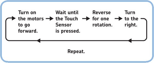
Figure 6-7. The program flow in the TouchAvoid program. After turning right, the program returns to the beginning and repeats.
You can accomplish each action in this diagram with one programming block. You’ll use a Move Steering block in On mode to turn on the motors and then use a Wait block to wait for the sensor to be pressed. (Note that while the program waits, the robot keeps moving forward.)
Once the sensor is triggered, you use a Move Steering block to reverse and then another to turn around, both in On For Rotations mode. After the robot turns around, the program returns to the beginning, which is why you must place the four blocks you use inside a Loop block configured in Unlimited mode. Create the program now, as shown in Figure 6-8.
Discovery #24: Avoid Obstacles and a Bad Mood!
Expand the TouchAvoid program by making it display a happy face on the EV3’s display as the robot moves forward and a sad face when it’s reversing and turning.

Figure 6-8. The TouchAvoid program. The Wait block is configured in Touch Sensor - Compare - State mode.
Discovery #25: Easy Push!
Can you make the EXPLOR3R drive backward as long as you press the bumper, and can you make the robot stop when you release the bumper? This behavior should continue until you end the program manually. Test your program by keeping the bumper pressed manually. (This makes it seem as though you’re pushing the robot backward, but actually the robot is doing all the hard work.)
So far we’ve used the Wait block in Compare mode to make the program pause until the Touch Sensor reaches a state of your choice (pressed or released). Now we’ll create a program with a Wait block in Change mode that will pause the program until the sensor state changes (either from released to pressed or from pressed to released). Create and run the WaitForChange program, as shown in Figure 6-9.
If the bumper is released when the program starts, the robot should drive until it hits an object and then stop. If the bumper is already pressed when the program starts, the robot should continue to try to go forward until the sensor is released and then stop.
For most programs, it’s best to use the Compare mode because doing so makes predicting your robot’s behavior easier. Regardless of the initial state of the sensor, the robot will always wait to change its behavior until the Touch Sensor reaches the state of your choice.
As you learned in Chapter 5, you can configure a Loop block to loop a certain number of times, loop for a specified number of seconds, or loop endlessly. You can also program a Loop block to stop repeating based on sensor input. For example, you can make your robot drive back and forth until the Touch Sensor is pressed. To configure the Loop block like this, select the Touch Sensor – State mode, as shown in Figure 6-10. As before, choose 1 in the Port setting.
Create the LoopUntilTouch program and run it to see how it works. You should notice that the program checks the sensor measurement only once each time the blocks inside the loop have completed. For the loop to end, the sensor will need to be pressed just after the robot moves forward. If the sensor is not pressed at this point in the loop, the robot moves back and forth once more before checking the state of the Touch Sensor again.
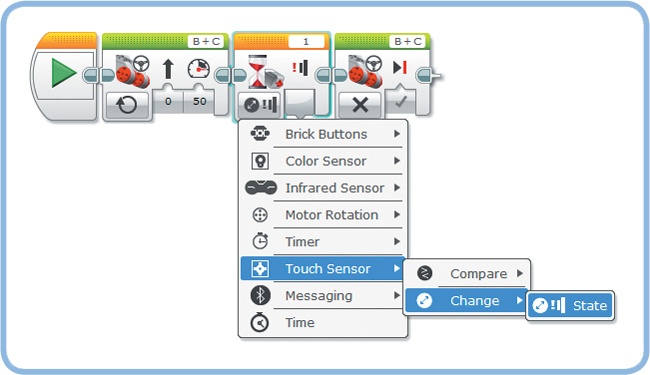

Figure 6-10. The LoopUntilTouch program. To configure the Loop block, click the Mode Selector and choose Touch Sensor – State.
This is the expected behavior for the Loop block, but sometimes you’ll want the loop to end even if you don’t press the sensor at exactly the right time. To accomplish this, set the state setting to Bumped (2) and run the program again. In this configuration, the loop doesn’t check whether the Touch Sensor is pressed at the end of the loop; rather, it checks whether you bump (press and release) the sensor at any time during the loop. If you do, the blocks should stop repeating after they complete the current run. (The EV3 continuously monitors the state of the Touch Sensor while the loop runs so that you don’t have to worry about it.)
Discovery #26: Happy Tunes!
Use a Loop block to make the robot play a tune until the robot’s bumper is pressed, at which point the robot should scream and quickly turn around.
Hint
You can use the My Block that you made in Discovery #19 in Discovery #19: My Tune! for your tune. If you have yet to create your own tune, simply select a sound file from the list in a Sound block.
You can use a Switch block to have a robot make a decision based on a sensor measurement. For example, you can make your robot drive backward if the Touch Sensor is pressed or say “No Object” when it’s not pressed, as shown in Figure 6-11.
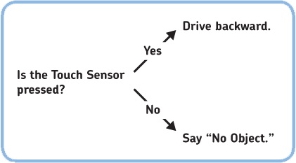
The Switch block checks whether a given condition (such as “The Touch Sensor is pressed”) is true or false, as shown in Figure 6-12.
The Switch block in this example contains two sequences of blocks; the switch decides which sequence to run based on whether the condition is true or not. If the condition is true, the block in the upper part of the switch is run, and the robot moves backward; if the condition is false, the lower blocks are run, and the robot should say “No Object.”
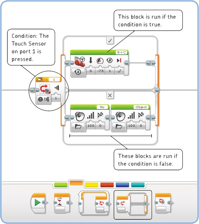
Figure 6-12. The Switch block checks whether the condition is true or false and runs the appropriate blocks. You specify the condition using the mode and settings on the Switch block.
You define the condition by configuring the mode and settings of the Switch block. Once the program arrives at the Switch block, the robot checks whether the condition is true. Then, it decides which set of programming blocks in the switch to run.
There’s a mode for each sensor; in this case, you’ll choose the one for the Touch Sensor, namely Touch Sensor – Compare – State (the only available option). Once you’ve chosen this mode, you can specify in the state setting whether the Touch Sensor must be pressed (1) or released (0) for the condition to be true. As before, set Port to 1 to specify how the Touch Sensor is connected to your EV3.
The TouchSwitch program you’ll now create makes the robot drive forward for three seconds. Then, if the Touch Sensor is pressed, the robot reverses for a short while. If the sensor is not pressed, the robot instead says “No Object.” Finally, regardless of the Switch block’s decision, the robot plays a tone. Now create the program, as shown in Figure 6-13.
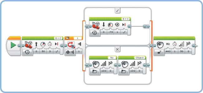
Try running this program a few times, and determine when you need to press the Touch Sensor to make the robot go backward. Your experiments should show that the robot takes a measurement when the Switch block runs and that it uses this single measurement to determine whether the condition is true. In this program, the sensor measurement is taken just after the robot finishes going forward. When either the reverse action or the “no object” action is complete, the tone plays.
There’s no limit to the number of blocks you can place inside a Switch block. If one part of a switch has multiple blocks, they’re simply run one by one. You can also leave one of the two parts of a Switch block empty, as shown in Figure 6-14.
Run this modified program to see what happens. If the condition is true (the bumper is pressed), the robot should say “Object” and move backward, and the program should continue by playing the tone. If the condition is false (the sensor is not pressed), the program will find no blocks in the lower part of the switch and instantly move on to the Sound block after the switch.
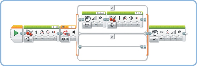
Figure 6-14. A modified version of the TouchSwitch program. The switch does not have any blocks to run if the condition is false, so the program immediately plays a tone after moving forward if the sensor is not pressed.
Discovery #27: Stay or Move?
Make the robot stand still for three seconds. Then, if the Touch Sensor is released, the robot should turn around and drive forward for five wheel rotations. But if the sensor is pressed, the robot should do nothing, and the program should end immediately.
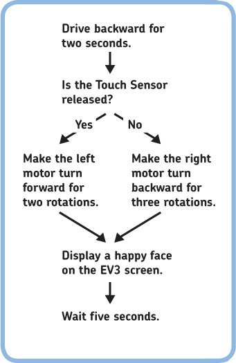
Discovery #28: Difficult Decisions!
Let’s practice with the Switch block! Create a program to implement the decision tree shown in Figure 6-15. How do you configure the Switch block, and why do you have to put a Wait block at the end of the program?
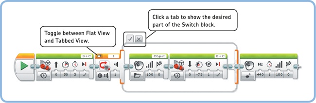
Normally, you see the complete Switch block on your screen in Flat View. When you make large programs containing Switch blocks, it’s easy to lose track of how your program works. In such cases, you can display the block in Tabbed View to decrease the size of the Switch block, as shown in Figure 6-16. Both parts of the switch are still in the program, but they’re on separate tabs, which you can open by clicking them.
Every time your program arrives at the Switch block, it checks the state of the Touch Sensor to decide whether the blocks in the true or false part of the switch should be run.
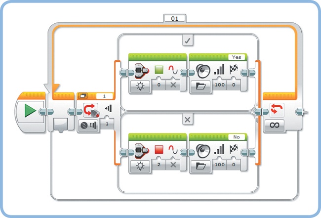
To have a robot check a condition more than once, you can drag a Switch block into a Loop block. For example, you could program a robot to say “Yes” if the Touch Sensor is pressed and to say “No” otherwise. If you place a Switch block with this configuration in a Loop block, the robot will keep checking the sensor reading and continue to say “Yes” or “No” accordingly.
Now create the RepeatSwitch program shown in Figure 6-17.
If you use sensor input in any programs with Wait, Loop, and Switch blocks, you often have to choose among Compare, Change, and Measure when configuring a block’s mode. You’ll see more examples of these modes as you read on, but let’s take some time to look at them side by side to see how they work.
Compare mode (![]() ) makes your robot take a sensor value and check it against the condition as specified in the block’s settings. A condition is a statement like “The Touch Sensor is pressed,” “The measured light intensity is less than 37%,” or “The Color Sensor sees red or blue.”
) makes your robot take a sensor value and check it against the condition as specified in the block’s settings. A condition is a statement like “The Touch Sensor is pressed,” “The measured light intensity is less than 37%,” or “The Color Sensor sees red or blue.”
A Wait block in Compare mode keeps taking new sensor measurements until the condition becomes true. When it’s true, the program moves on to the next block in line (see Figure 6-6).
A Loop block in Compare mode checks the condition against a new sensor value each time it’s done running the blocks inside the loop. If the condition is true, the program moves on to the block after the loop; if it’s false, the loop runs again (see Figure 6-10). Loop blocks are always in Compare mode.
A Switch block in Compare mode runs the sequence of blocks at the top if the condition is true; it runs the blocks at the bottom if it’s false (see Figure 6-13).

Change mode (![]() ) is available only in Wait blocks. A Wait block in Change mode takes an initial measurement and keeps taking new measurements until it finds one that’s different from the first one. For example, if the Touch Sensor is pressed when the block starts, it waits until the Touch Sensor is released. Then, the program continues with the next block (see Figure 6-9).
) is available only in Wait blocks. A Wait block in Change mode takes an initial measurement and keeps taking new measurements until it finds one that’s different from the first one. For example, if the Touch Sensor is pressed when the block starts, it waits until the Touch Sensor is released. Then, the program continues with the next block (see Figure 6-9).
Measure mode (![]() ) is available only in Switch blocks. A Switch block in Measure mode contains a set of blocks to run for each possible sensor value. You’ll see how this works in Chapter 7 when you create a program that does something different for each color the Color Sensor can see.
) is available only in Switch blocks. A Switch block in Measure mode contains a set of blocks to run for each possible sensor value. You’ll see how this works in Chapter 7 when you create a program that does something different for each color the Color Sensor can see.
The text usually makes clear which mode you should use for the example programs in this book, but all of the information you need is also visible in the programming diagrams. If you’re not sure which mode to choose, just look at the icons on each block, as shown in Figure 6-18.
Once you’ve selected the sensor (1) and made a choice of Compare, Change, or Measure (2), you choose the sensor operation mode (3). The Touch Sensor measures just one thing (the state of the red button), but the Color Sensor has three operation modes, as shown in Figure 6-18. As you practice with each mode in the next chapters, you’ll be able to create your own programs with sensors in no time.
In this chapter, you’ve learned that robots use sensors to gather input from their environment. You’ve also learned how to create programs for robots with sensors using Wait, Loop, and Switch blocks.
You’ve been using only the Touch Sensor so far, but you can use all the programming techniques you’ve learned in this chapter when working with the other sensors. You’ll continue with the Color Sensor in Chapter 7, you’ll learn about the Infrared Sensor in Chapter 8, and you’ll meet the built-in Rotation Sensors and the Brick Buttons in Chapter 9. Before you continue, practice your sensor-programming skills by solving these Discoveries.
Discovery #29: Choosing Directions!
Expand the TouchAvoid program from Figure 6-8 to make the robot go right after running into the first object and left when the sensor is pressed again. The next obstacle should result in a right turn again, and so on.
Discovery #30: Wait, Loop, or Switch?
Program the robot to wait for a Touch Sensor press. Then, if the sensor is still pressed after five more seconds, make the robot say “Yes.” Otherwise, make it say “No.”
Discovery #31: Brick Buttons!
As you’ll see in Chapter 9, you can use most of the Brick Buttons the same way you’ve used the Touch Sensor. Without skipping ahead, can you make the robot say “Left” if you press the Left button on the EV3 Brick and “Right” if you press the Right button? Can you make it say “Up” and “Down” when you push the Up and Down buttons as well?
Design Discovery #4: Intruder Alarm!
Can you turn your robot into an alarm that alerts you to intruders entering the room? Use the Touch Sensor as a switch that gets activated when someone breaks into the room. Play a loud beeping sound when this happens.
Design Discovery #5: Light Switch!
Design a robot that toggles the light switch in your room whenever you press the Touch Sensor. Each time you press the sensor, the robot should switch the light on or off. You can add the Medium Motor to the EXPLOR3R to do this, or you can design a completely new robot dedicated to this task.