The Infrared Sensor lets your robot “see” its surroundings by measuring the approximate distance to an object using infrared light. In addition, the sensor gathers information from the infrared remote (also called the beacon). The sensor can detect which buttons on the remote you press, approximately how far away the remote is, and the relative direction, or heading, from the robot to the remote.
You can implement each of these features in your programs using the Infrared Sensor in four different modes: Proximity, Remote, Beacon Proximity, and Beacon Heading (see Figure 8-1). You can actually see the infrared light from the beacon by viewing it with a digital camera, such as the one in a smartphone. You can also see a faint light coming from the sensor if it’s in Proximity mode. In this chapter, you’ll learn how each mode works as you create programs for the EXPLOR3R to make it avoid obstacles, respond to remote control commands, and find the beacon.
The robot measures the distance from the sensor to an object with Proximity mode. Rather than measuring this distance in inches or centimeters, the sensor gives you the distance as a percentage from 0% (very close) to 100% (very far). Go to Port View on the EV3 brick, choose input port 4, and select IR-PROX (short for infrared proximity) to see the sensor value.
The sensor value is determined by measuring how much of the infrared light it emits gets reflected back. The closer an object is to the sensor, the more light is reflected back to the sensor. Some surfaces reflect infrared light better than others, which makes them seem closer. For example, a white wall might appear to be closer than a black wall, even though they are actually the same distance from the sensor.
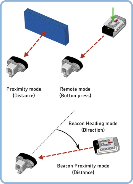
Figure 8-1. The operation modes of the Infrared Sensor. The red dashed lines represent the invisible rays of infrared light. If you block the path between the sensor and the remote, the sensor won’t be able to get a correct measurement.
Although the sensor doesn’t measure the exact distance to an object, it’s good at seeing whether or not an obstacle is in the way. The sensor value should be 100% when the sensor doesn’t see anything, and the value should drop to around 30% if the robot gets close to a wall. If you program the robot to drive forward but then move away if it sees something closer than 65% (the threshold value), you’ll have an obstacle-avoiding robot. The ProximityAvoid program in Figure 8-2 uses a Wait block to look for measurements less than 65%.
You’re not limited to using just one sensor in your program. In fact, you can use all of the sensors connected to your EV3 in a single program. This can make your robot more reliable.
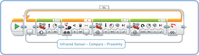
Figure 8-2. Create a new project called EXPLOR3R-IR with a program called ProximityAvoid, and configure the blocks as shown. Notice the similarity with the TouchAvoid program you made in Chapter 6.
For example, the Infrared Sensor doesn’t always see small objects in the robot’s path, but the Touch Sensor is good at detecting these. On the other hand, the Touch Sensor won’t detect some soft obstacles, like a curtain, but the Infrared Sensor will. If you combine the sensor measurements, the EXPLOR3R is less likely to get stuck somewhere when it drives around.
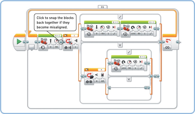
One way to combine sensor measurements is to use a Switch block within a Switch block, resulting in the program flow in Figure 8-3. Create and run the CombinedSensors program that implements this decision tree, as shown in Figure 8-4.
Note
Don’t forget to reconnect the Touch Sensor attachment you made in Chapter 6 to your robot. The Touch Sensor should be connected to input port 1.
Discovery #42: Close Up!
Make the robot repeatedly say “Detected” if it sees an object closer than 50%, and make it say “Searching” otherwise. Then try out other threshold values, such as 5% or 95%, to see how close and how far the sensor can detect objects reliably. The sensor doesn’t measure an exact distance, and you’ll find that the results vary depending on what kind of object you’re trying to detect.

In Remote mode, the Infrared Sensor detects which buttons on the infrared remote you press, allowing you to make programs that do something different for each button. This is how you were able to remotely control your robot in Chapter 2. The IR Control application you used on the EV3 brick is actually a program that makes the robot steer in different directions according to the buttons you press. The sensor can detect 12 button combinations, or Button IDs, as shown in Figure 8-5.
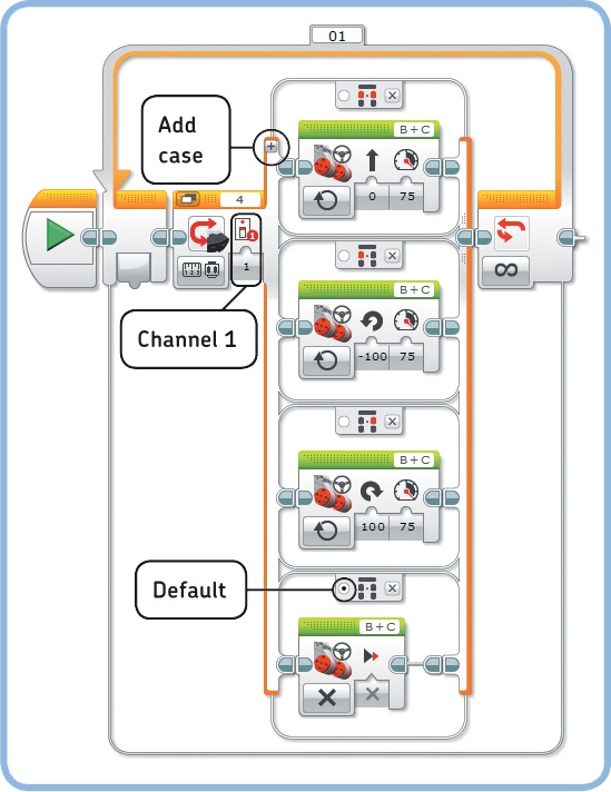
A Switch block in Measure mode lets you choose a set of blocks to run for each sensor value—each Button ID, in this example. The CustomRemote program uses such a switch to make the EXPLOR3R drive forward if the two top buttons are pressed (Button ID 5). It steers left when the top-left button is pressed (ID 1) and right when the top-right button is pressed (ID 3), and it stops if no buttons are pressed (ID 0). Stopping is the default, so the robot also stops if you press an unspecified button combination.
Because the program is configured to listen to the remote on channel 1, your remote should be on channel 1 as well (see Figure 2-10). If you have another EV3 robot, switch it to a different channel (2, 3, or 4) to avoid interference. Create and run the program now (see Figure 8-6), and drive your robot around with the remote.
This technique is especially useful (and fun!) because now you can make a custom remote control program for all of your robots. For example, in Chapter 12 you’ll build a Formula EV3 Race Car that drives and steers differently than the EXPLOR3R. The normal IR Control application won’t work for that robot, but you can solve this problem by making your own program to drive and steer the robot.

Figure 8-5. The Infrared Sensor can detect 12 button combinations (Button IDs) on the remote control. Pressed buttons are shown in red.
Discovery #44: Unlock the Remote!
Can you protect your program with a secret button combination? Add two Wait blocks just before the Loop block in the CustomRemote program. Make these blocks wait for you to press Button IDs 10 and 11, respectively, before the rest of the program will run. (As an extra challenge, try making the code more secure using the technique you learned in Design Discovery #8 in Design Discovery #8: Safe Deposit!.)
In addition to detecting which button you’ve pressed on the infrared remote, the Infrared Sensor can detect the signal strength and the direction the signal is coming from when you press any of the buttons. The robot can use this information to locate the remote, or beacon, and drive toward it.
In Beacon Proximity mode, the sensor uses the beacon’s signal strength to calculate a relative distance ranging from 1% (the beacon is very close to the sensor) to 100% (it’s very far). For best results, hold the beacon at roughly the same height as or just above the sensor and point it at the eyes of the robot (see Figure 8-1).
The little green light on the beacon indicates it’s busy sending a signal. It doesn’t matter which button you press when it comes to beacon proximity or heading, but it’s handy to use the button at the top (Button ID 9). The green light turns on when you press it once, and it turns off when you press it again, so you don’t have to keep the button pressed all the time.
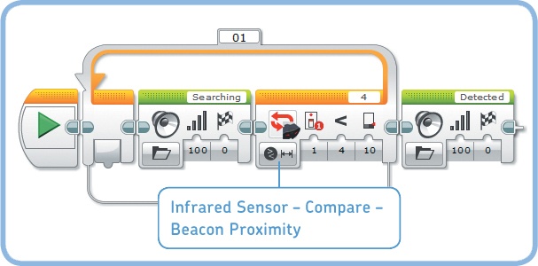
Now you’ll make the BeaconSearch1 program that has the robot repeatedly say “Searching” until the Infrared Sensor measures a beacon proximity of less than 10%. In other words, it will keep saying it’s searching until you hold the beacon very close to the sensor. You can accomplish this with a Loop block, configured as shown in Figure 8-7. After the loop finishes, the robot says “Detected.”
Note
The sensor can also tell you whether it sees a signal at all. You could make the robot stop moving if no signal is detected, for example. This requires the use of a few blocks you haven’t seen yet, but we’ll get back to that in Chapter 14.
The Infrared Sensor can measure the direction of the beacon’s signal using Beacon Heading mode. This heading gives the robot a rough sense of the angle between the beacon and the sensor. The measurement is a number between −25 and 25, as shown in Figure 8-8. The sensor doesn’t provide a precise angle, but it’s good enough to determine whether the beacon is to the robot’s left (negative values) or right (positive values).
The sensor is able to see the beacon in all directions—even if it’s behind the sensor—but the measurement is most reliable in the green region of Figure 8-8. The heading value is zero if the beacon is directly in front of the sensor or right behind it, but it’s also zero when the sensor detects no signal at all.
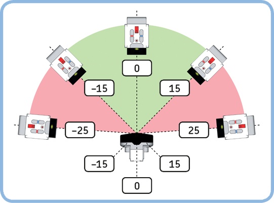
Figure 8-8. The Beacon Heading sensor value ranges between −25 and 25. Negative values indicate that the beacon is to the left of the sensor; positive values mean it’s to the right. A value near 0 means that the robot sees the beacon straight ahead or right behind it.
Information about whether the beacon is to the robot’s left or right is all you need to make the robot drive toward the beacon. When the sensor detects the beacon to the left, the robot should drive to the left. If the beacon is on the right, the robot should steer right. You can use a Switch block to see whether the Beacon Heading sensor value is less than (<) 0, indicating that the beacon is to the left.
If you continuously adjust the steering to the sensor measurement and drive forward at the same time, your program will make the robot find the beacon. Remove the Sound blocks from your previous program and add a Switch block with two Move Steering blocks to complete the BeaconSearch2 program, as shown in Figure 8-9. The loop makes the robot keep searching for the beacon until beacon proximity is below 10%; then the program ends.
Note
Remember to make the beacon transmit a signal continuously, either by keeping one of the buttons pressed or by toggling the button at the top (Button ID 9) so the green indicator light is permanently on.
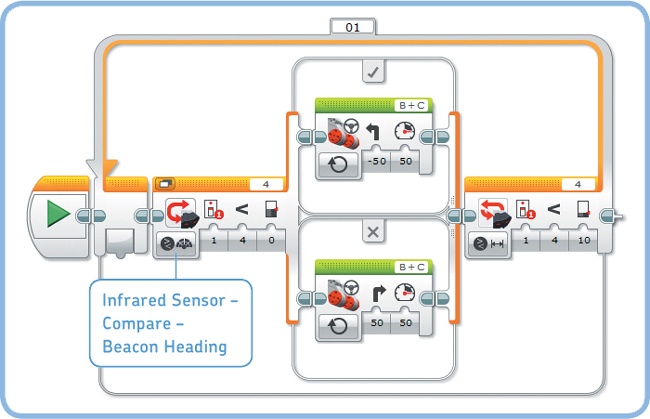
Figure 8-9. The BeaconSearch2 program makes the robot drive toward the beacon and stop when it’s very close to the beacon. If you move around with the beacon, the robot will follow you.
Discovery #45: Smooth Follower!
Can you expand the BeaconSearch2 program to make the robot drive toward the beacon more smoothly? Have the robot make soft turns (25% steering) if the beacon is in the green area of Figure 8-8 and sharp turns (50% steering) if it’s in the red area.
Hint
Use the techniques you learned in following a line more smoothly. You don’t need to calculate threshold values; they’re given in Figure 8-8.
Combining multiple operation modes of the Infrared Sensor in one program can make your robot behave unexpectedly because the sensor needs time to switch from one mode to the other. (Beacon Proximity and Beacon Heading are the only operation modes of the Infrared Sensor you can use together without delays.)
For example, say you wanted to change the Loop block in the CustomRemote program (see Figure 8-6) to loop until the sensor detects a proximity below 10%. A Switch block would detect the pressed button in Remote mode, and then the Loop block would try to read the proximity value in Proximity mode. But because the sensor has to change from one mode to the other each time, the program would run very slowly, and your robot may not respond properly to the remote control. (Try this out if you like).
If timing isn’t critical, though, it’s fine to use different modes in one program. For example, the MultiMode program in Figure 8-10 works as expected. First, it waits until you press the top-right button on the remote (Button ID 3), after which you’ll hear a beep. Then, it says “Yes” if the proximity measurement is lower than 30%; otherwise, it says “No.” You’ll hear a gap between the beep and the spoken word—that’s the delay caused by switching from Remote mode to Proximity mode.

The Infrared Sensor lets your robot detect objects in its environment from a distance. When combined with the infrared remote, the sensor can act as a remote control receiver and a beacon detector. You’ve also seen how to combine the Touch Sensor and the Infrared Sensor to make the robot avoid obstacles more reliably. You can, of course, add the Color Sensor for even more sophisticated programs. Before you go on, practice your building and programming skills with these Discoveries!
Discovery #46: Follow Me!
Can you make the EXPLOR3R follow you in a straight line while keeping a fixed distance? Use the Infrared Sensor in Proximity mode to detect the distance to your hand (keep it in front of the robot). The robot should follow as you move your hand away; it should reverse if you move your hand closer. Make the robot stand still if it sees your hand at a distance between 35% and 45%.
Discovery #47: Sonar Sounds!
Can you make the EV3 play sounds to guide you toward the beacon with your eyes closed? Make it play tones at different frequencies and volumes based on the location of the beacon. Play low tones (400 Hz) if the beacon is to the left of the sensor and high tones (1000 Hz) if the beacon is to the right. The closer you are to the beacon, the louder the sound should be.
Hint
First, use a Switch block to determine whether the beacon is to the left or to the right. Next, in both parts of this switch, place a Switch block to determine whether the beacon is close or far away. Then, you’ll have four spots to place a Sound block, each configured to play one of these tones: low and loud, low and soft, high and loud, and high and soft.
Design Discovery #9: Railroad Crossing!
Can you design an automated railroad crossing for LEGO model trains? Use a motor to move a barrier that stops cars from crossing the railway when a train passes. Use the Infrared Sensor or the Color Sensor to spot when a model train approaches and when the barriers should be lowered as well as when they should be raised again.
Design Discovery #10: Foolproof Alarm!
Can you use all three sensors in the EV3 set to create an intruder alarm that never fails? Use the Touch Sensor to detect a door that’s being opened (Design Discovery #4 in Design Discovery #4: Intruder Alarm!), use the Color Sensor to detect people stepping through the doorway (Design Discovery #7 in Design Discovery #7: Doorbell!), and use the Infrared Sensor in Proximity mode to detect movements near an object of interest, such as a phone.