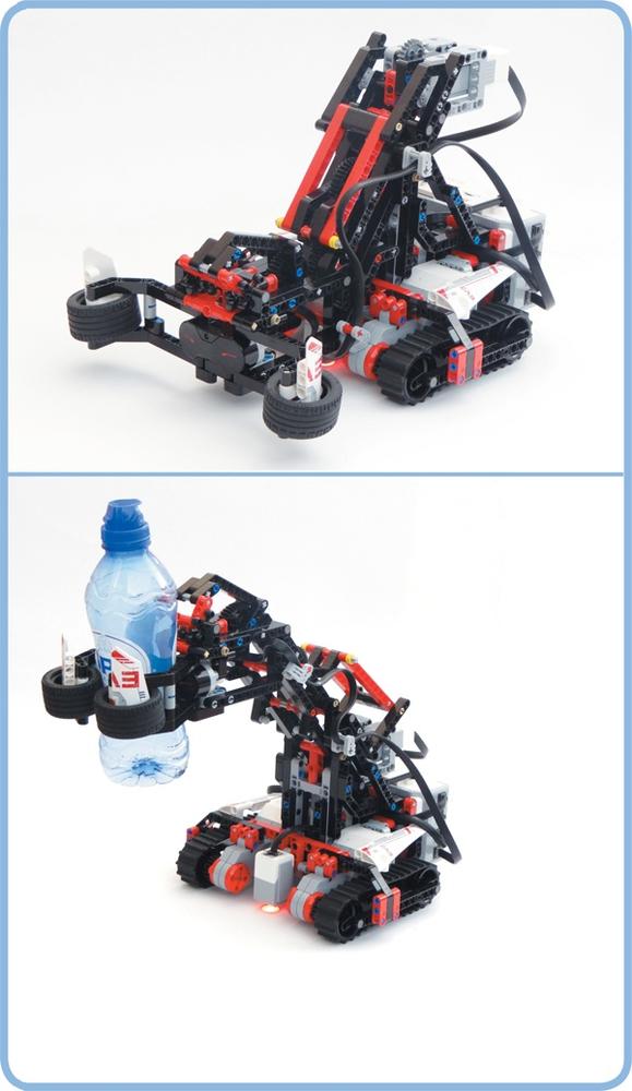
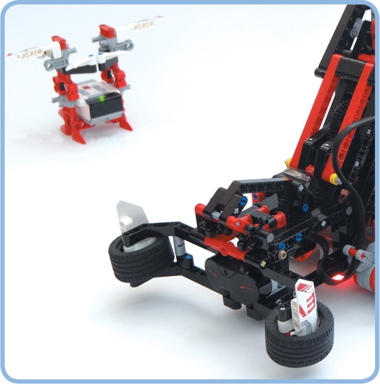
Throughout the previous chapters, you’ve learned a great deal about programming EV3 robots. Now you’re ready to build and program the more sophisticated robots in this part of the book. This chapter will teach you to build and program the SNATCH3R, a robotic arm that can find and pick up objects, as shown in Figure 18-1.
You’ll first create a program that lets you control the robot remotely so you can test its mechanical functions, and then you’ll program it to find and grab the infrared beacon autonomously. You’ll use data wires and variables to make the robot scan its surroundings so that it can find the beacon from up to 2 meters (6 feet) away, even if it’s behind the robot.
The Discoveries throughout this chapter will help you see how the programs really work so you can expand on them with more features. For example, you’ll be challenged to make the robot follow lines with the Color Sensor and pick up objects in its path.
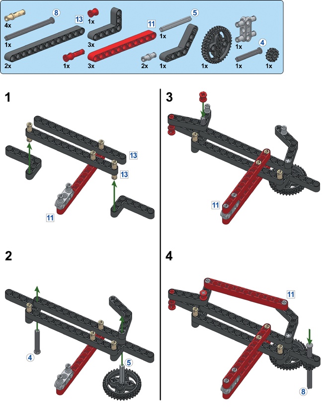
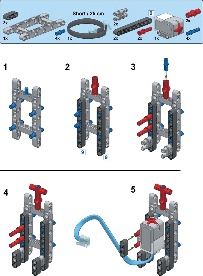
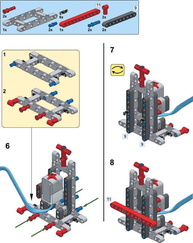
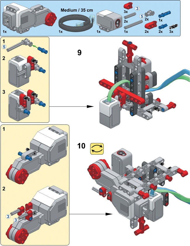
The SNATCH3R uses two Large Motors to control a set of treads for driving, but the really cool part of this robot is its multifunctional grabber. Normally, grabbing and lifting objects requires two motors: one to grab the object and another to lift it. The SNATCH3R requires just one Medium Motor to accomplish both tasks because of a specialized construction of LEGO beams, axles, and gears. To better understand how the robot works, you’ll build a simplified mechanism using the instructions on the next page.
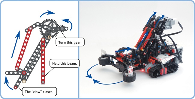
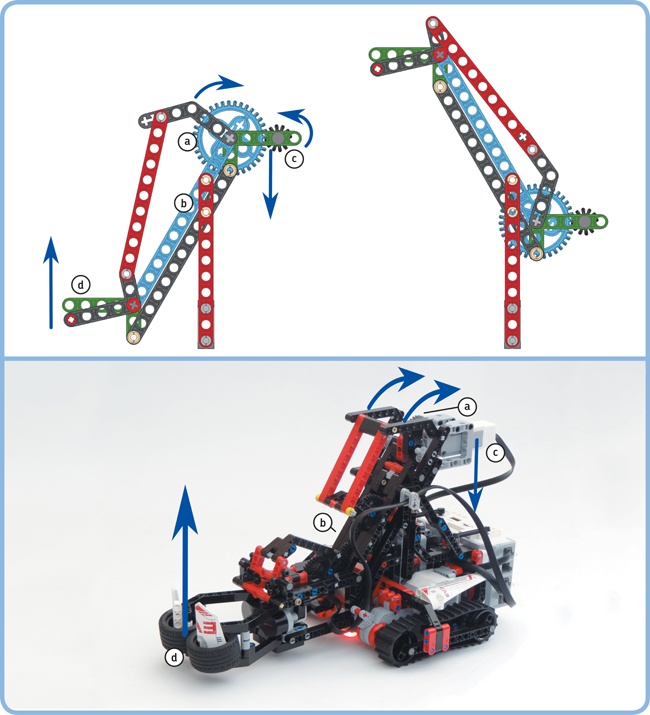
To see how the grabber mechanism works, hold the red beams of the sample mechanism with one hand and use your other hand to turn the 12T gear by rotating its axle (see Figure 18-2). Try not to push the axle up or down while rotating it; the mechanism should do this on its own.
When you turn the small gear, the 36T gear will begin to pull the red beam upward so that the “claw” closes. Something similar happens in the SNATCH3R mechanism. The Medium Motor drives a 24T gear with a worm gear, which starts a chain reaction that ultimately causes the grabber to grasp objects positioned between its claws. When the motor spins backward, the reverse happens and the grabber opens.
Once the grabber is closed, the beams and gears that caused it to close can no longer move. In the simplified mechanism (see Figure 18-3, top), this means that the 36T gear (a) hardly moves relative to the beam shown in blue (b). As a consequence, you can rotate the blue beam relative to the green beams (c and d) by rotating the 36T gear, and doing so raises the grabber into the air.
Similarly, as shown in Figure 18-3 (bottom), the 24T gear in the SNATCH3R (a) becomes locked to the beams in the grabber mechanism (b), and rotating it relative to the motor compartment (c) by turning the Medium Motor forward causes the grabber (d) to rise. When the motor rotates backward, the grabber lowers.
Note that the two green beams in the sample mechanism (c and d) are always positioned horizontally, regardless of the arm’s position. Similarly, the motor compartment (c) and the grabber (d) in the SNATCH3R remain positioned horizontally.
A Touch Sensor in the base of the SNATCH3R detects whether the grabber is lifted all the way up. Therefore, to grab and lift an object, you rotate the Medium Motor forward until the Touch Sensor is pressed. If the arm starts out in the lowered position with its claws open, the motor will have turned for 14.2 rotations when it reaches the Touch Sensor. Therefore, to lower and release the object, you rotate the motor backward for 14.2 rotations.
But how does the mechanism know to close the grabber before raising it and, when reversing, to lower it before opening the grabber? The mechanism doesn’t “know” to do this, of course, but it’s designed so that this behavior results naturally because of gravity. Closing the claws requires less energy than raising the grabber, so the claws always close first when the motor turns forward. Similarly, lowering the grabber requires less energy than opening the claws, so the grabber always lowers first when the motor turns backward. The details are beyond the scope of this book, but you can see that gravity plays a role by holding the sample mechanism on its side. You should find that without gravity to pull the claw downward, the mechanism doesn’t work properly.
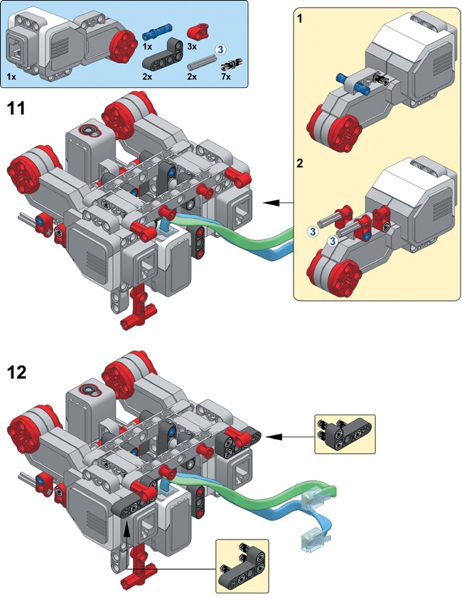
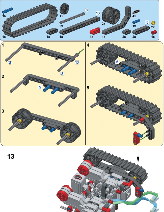
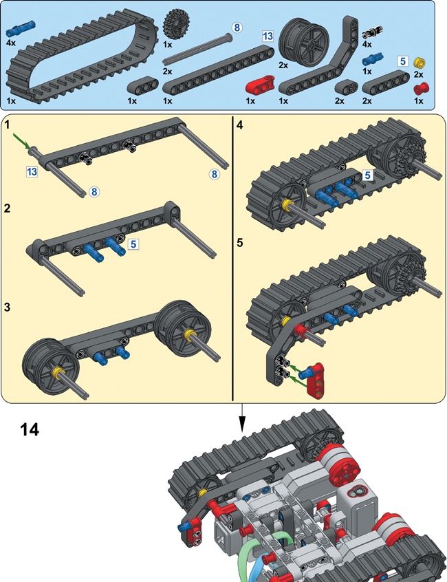
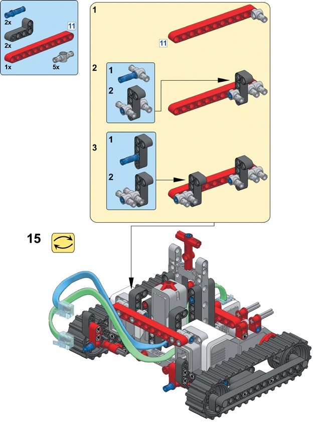
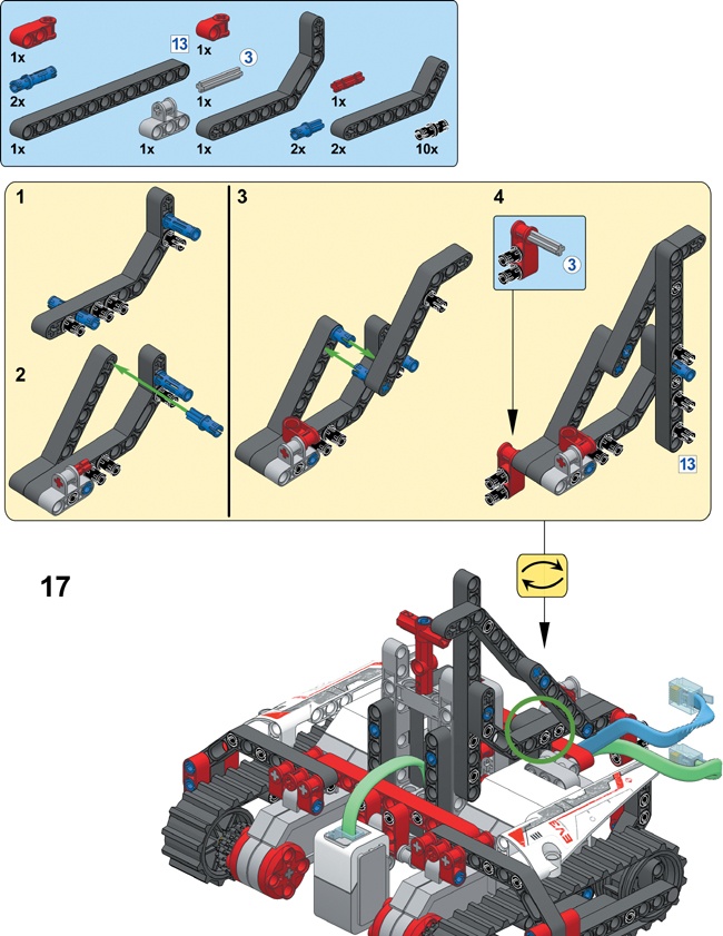
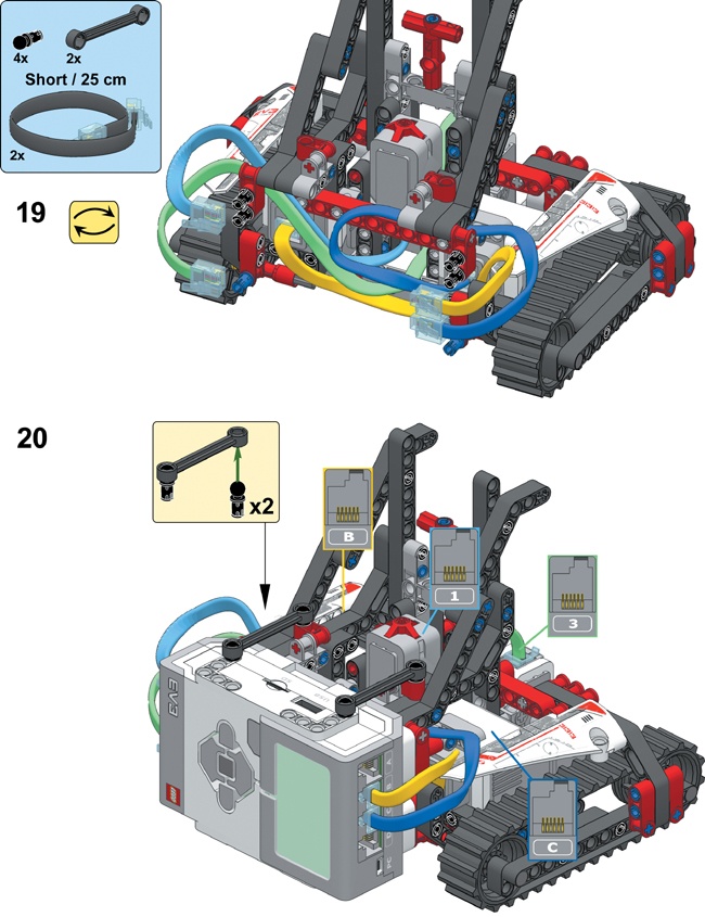
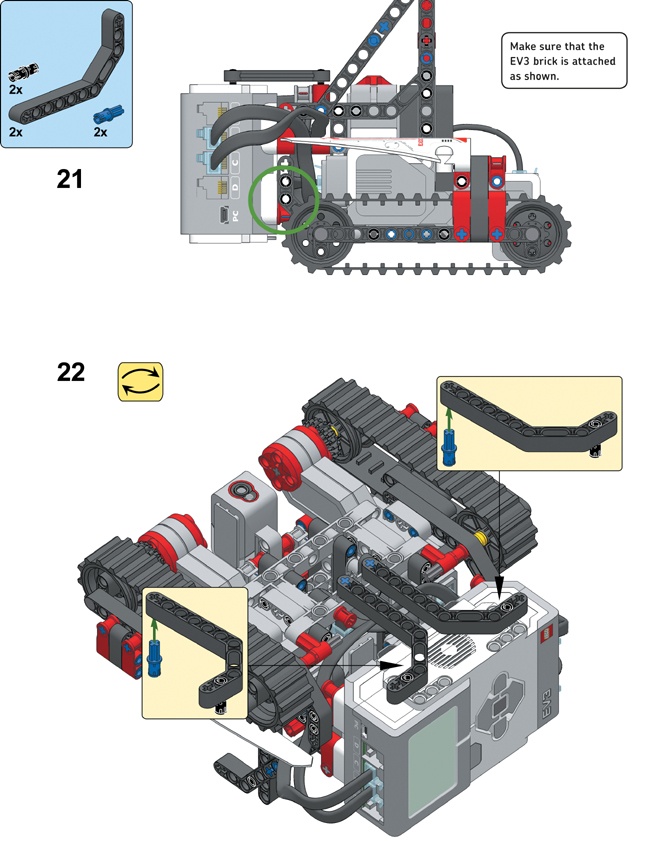
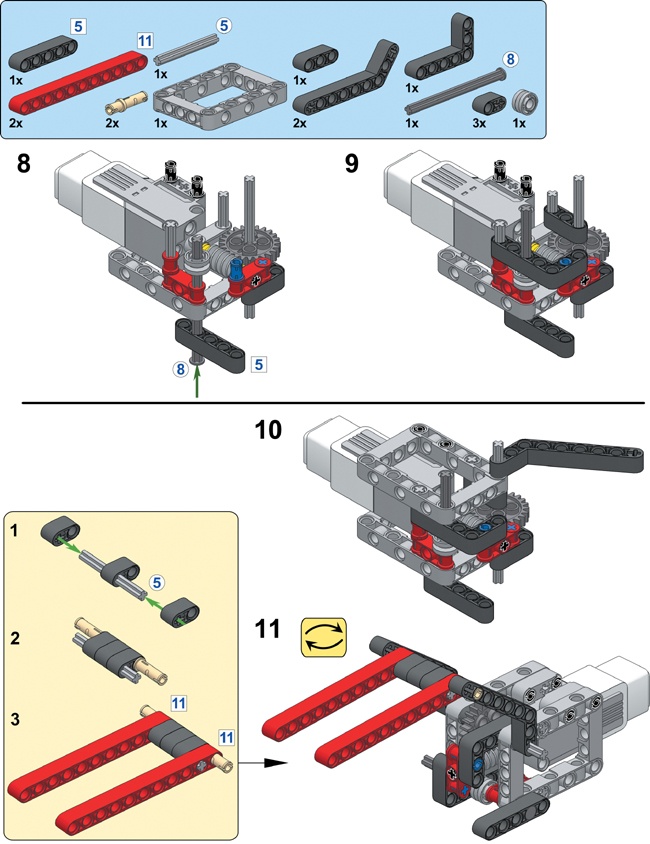
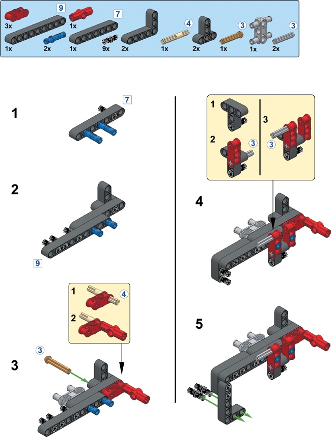
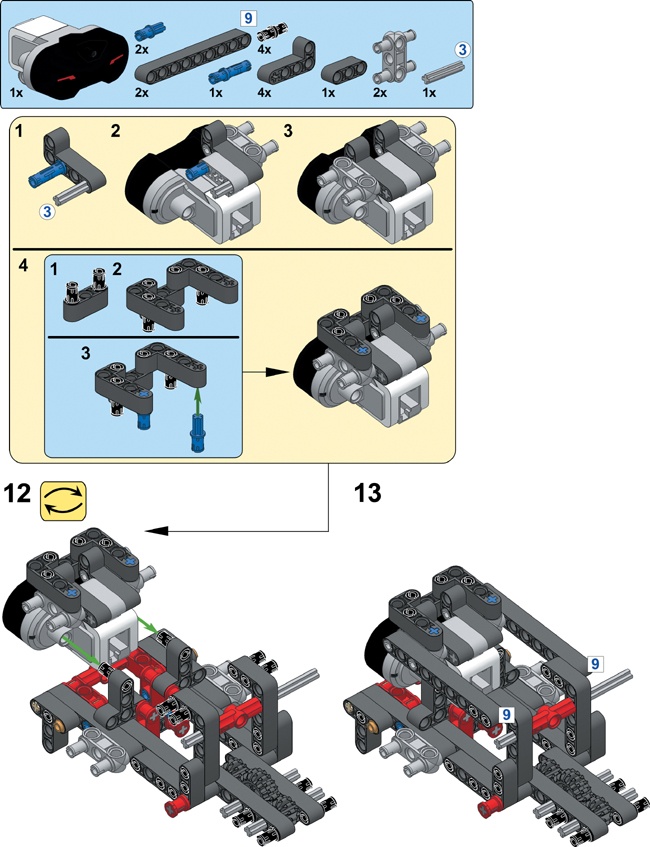
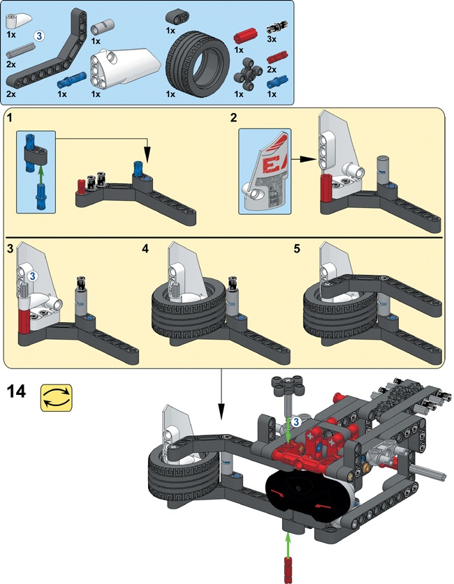
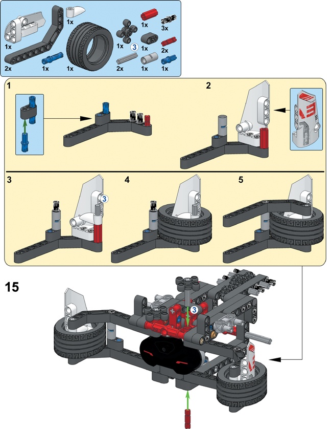
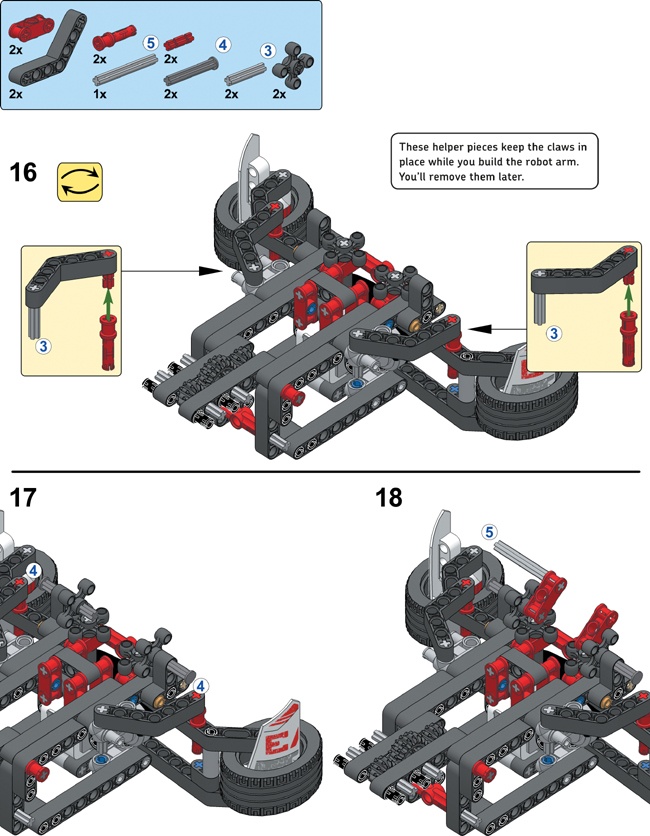
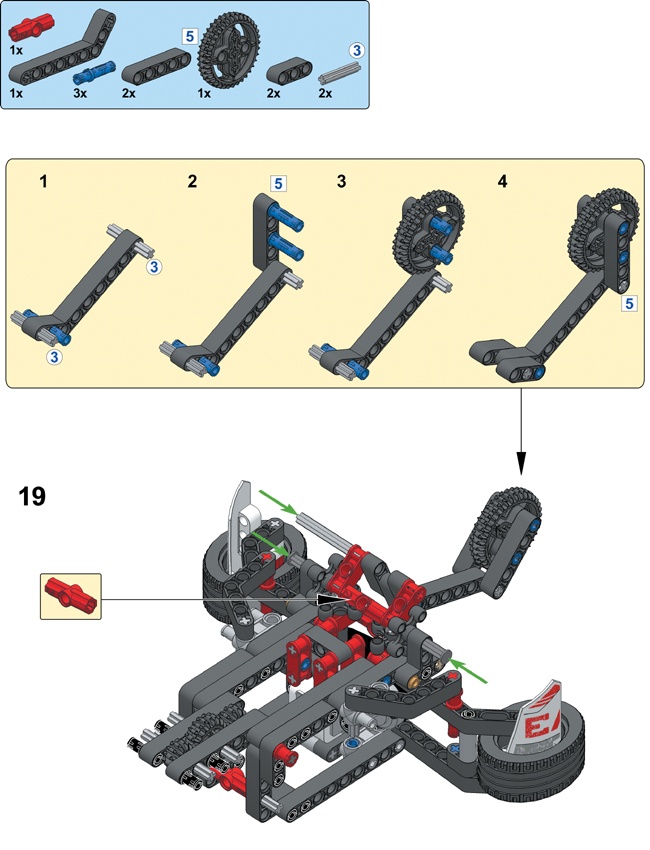
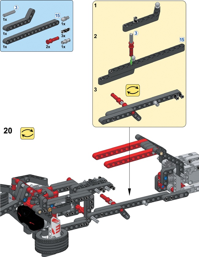
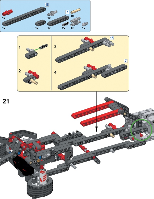
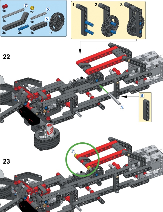
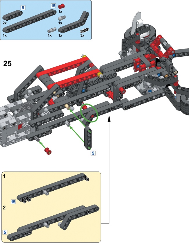
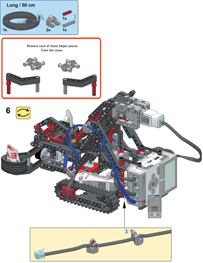
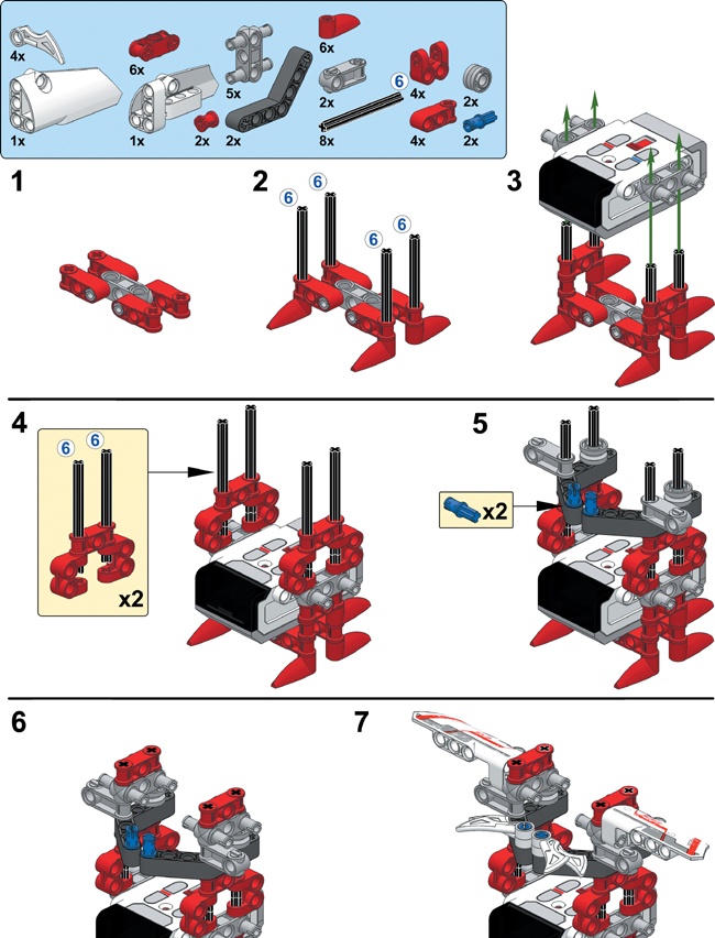
Now that you’ve gotten a sense of how the SNATCH3R’s grabber mechanism works, it’s time to build the robot to see the full mechanism in action. Follow the directions on the next pages, but first take the sample mechanism apart and select the pieces you’ll need for the complete model, as shown in Figure 18-4.


Now that you’ve built the robot, you’re ready to test its mechanical functions by creating a remote control program. You’ll drive the robot using Move Steering blocks, and you’ll create three My Blocks to control the grabber.
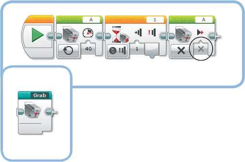
To grab an object and raise the grabber, the Medium Motor must rotate forward until the Touch Sensor inside the robot’s base is pressed. You’ll limit the motor speed to 40% to reduce the amount of power required to drive the motor.
Create a new EV3 project called SNATCH3R, place three blocks on the Canvas as shown in Figure 18-5, and turn them into a My Block called Grab. Because the worm gear in the mechanism prevents the motor from turning when the motor isn’t powered, setting the Brake at End to false is sufficient to keep the motor in place, and doing so saves some battery power.
When the program starts to run, the grabber can either be lowered with its claws open, lifted all the way up with its claws closed (see Figure 18-1), or in any intermediate position. To prevent damage to the mechanism and the motor, it’s important keep the grabber mechanism between these two boundaries by limiting how far the motor can turn.
You’ll control the upper boundary with the Touch Sensor: If the sensor is pressed, the motor shouldn’t move any farther forward. You’ll control the lower boundary using the Rotation Sensor of the Medium Motor: If the sensor value is less than 0 degrees, the motor shouldn’t move any farther backward.
To make this work, you’ll need to make sure the Rotation Sensor value is 0 degrees when the grabber is in the lowered position before the program begins. To accomplish this, raise the grabber until the Touch Sensor is pressed with the Grab My Block, and then lower it with a Medium Motor block configured to rotate the motor backward for 14.2 rotations. Finally, reset the Rotation Sensor value to 0. The distance between the upper and lower boundary is 14.2 rotations only when the claws are fully closed while the grabber is raised, so you need to make sure there aren’t any objects between the robot’s claws during this reset procedure.
Create the Reset My Block using the instructions in Figure 18-6. You’ll place this block at the start of every program for the SNATCH3R.
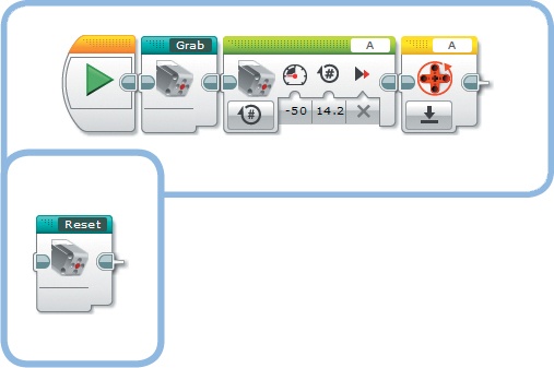
Figure 18-6. The Reset My Block places the grabber in the lowered position with its claws open at the start of your program and resets the Rotation Sensor to 0. The completed My Block is shown to the left. Note that the Grab My Block can be placed within the Reset My Block just as can any other normal block.
To lower the grabber and release the object, the Medium Motor should turn backward until the grabber is in the lowered position or, in other words, until the Rotation Sensor is at 0 degrees. Create the Release My Block, as shown in Figure 18-7.

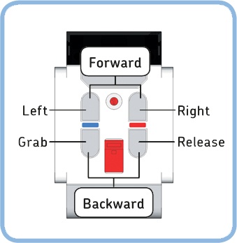
Now create and run the RemoteControl program, as shown in Figure 18-8. Drive the robot around, and make it grab and move objects using the infrared remote control, as shown in Figure 18-9. The SNATCH3R should be able to grab, lift, and move lightweight objects, such as empty soda cans and water bottles.
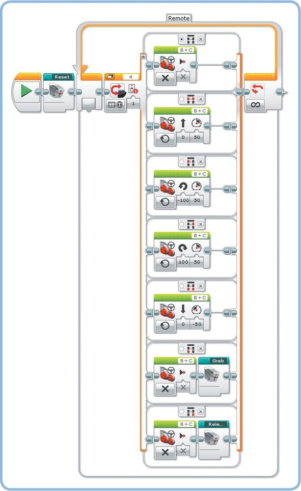
Figure 18-8. The RemoteControl program. The default case makes the motor stop moving so that the robot stops when you release the buttons.
Discovery #117: Extended Remote!
The RemoteControl program is great for testing the SNATCH3R’s functionality, but it’s a very basic program. Can you expand the program so you can make the robot drive in any direction, even while it’s busy grabbing or releasing an object?
Discovery #118: Remote Speed Control!
The Move Steering blocks in the RemoteControl program make the motors turn at 50% speed. However, sometimes you need to go faster (75%) to drive a large distance, and sometimes you need to go slower (25%) to accurately position the grabber in front of an object. Can you add remote control commands to change the speed of the motors?
If you experience any problems with the SNATCH3R’s grabber when running the RemoteControl program, you should solve them before proceeding to the next section. If you’re not sure how the SNATCH3R should work exactly, watch a video of the robot in action at http://ev3.robotsquare.com/. The following problems and solutions may help you troubleshoot your robot.
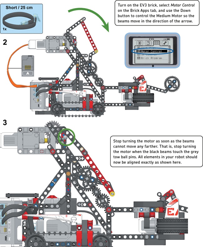
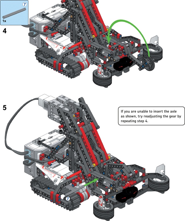
The grabber doesn’t close its claws before lifting. This can happen when you have accidentally misaligned the gears in the SNATCH3R’s arm. You can solve this problem by repeating the final building steps. To begin, remove the 7M axle you added in building the SNATCH3R by pushing it out of the robot with another axle. Then, reattach the helper elements to the claws (step 16 in building the SNATCH3R). You can then continue normally from building the SNATCH3R and test your robot again. Be sure to carefully observe the side views of the mechanism in building the SNATCH3R; each element of your robot should be aligned exactly as shown.
The cable connected to the Infrared Sensor prevents the claws from closing. This can occur if the cable is in the way of the 36T gear in the grabber. To check whether this is the problem you’re experiencing, try removing the cable completely and run the Reset My Block. If the grabber works fine now, you know the cable is the problem. Reattach the cable to your robot in such a way that it does not interfere with any of the gears.
The Medium Motor isn’t aligned parallel to the ground. This happens if the grabber isn’t correctly mounted to the robot’s driving base. To resolve this, remove the axles you added in building the SNATCH3R and carefully reattach them according to the instructions. The side views on that page show exactly in which holes you should mount these axles (some elements have been removed for better visibility).
You’ll now create a program that makes the SNATCH3R find, grab, lift, and move the infrared beacon. Each task should run autonomously, which means that all tasks are performed without human interaction.
Before you create the program, you’ll need to add some elements to the infrared beacon to make it easier for the robot to grab and lift it. Follow the instructions on the next page to build the IR “bug” using the remaining elements of the EV3 set. (If you used the Bill of Materials from Figure 18-4 to select the elements for your robot, you should have the required pieces at hand.)
You learned earlier that the robot can find the infrared beacon by driving to the left if the Infrared Sensor’s Beacon Heading is negative or to the right if it’s positive. Now that you’ve learned to use data wires and variables, you can create a more sophisticated program that makes the robot actually search for the beacon so that it will find the beacon up to 2 meters (6 feet) away, even if the beacon is behind the robot.
You’ll create a My Block called Search that has the robot scan its surroundings while making one complete turn to the left. Then, it turns right until it’s back at the position where it saw the beacon and its claws point toward the beacon. In principle, the robot could now find the beacon simply by driving straight ahead, but because the sensor measurement is not that accurate, you’ll create a My Block to make it easy to search for the beacon again if necessary.
To understand the search algorithm, you need to understand the Beacon Heading measurements that the robot takes as it makes one turn, as shown in Figure 18-10. When the sensor points in the direction of the beacon, the heading value (H) is 0 or close to 0. When the sensor points about 90 degrees away from the beacon, the heading is 25 or −25. Additionally, the sensor value is 0 when the robot faces away from the beacon because the SNATCH3R’s body blocks the view of the beacon and the sensor can’t determine the signal’s direction.
To find the beacon, we should therefore look for a value near 0 but not exactly 0. We should ignore 0 measurements because they might indicate that the beacon is behind the robot. Doing so will reduce the accuracy slightly, but at least you’ll be sure that the robot doesn’t drive away from the beacon. (In the final search phase, you’ll no longer ignore 0 values.)
Finally, it doesn’t matter whether we detect positive or negative values, so we can take the absolute value of the measurement. For example, −3 and 3 are equally close to 0.
To sum up, we have to look for the lowest measured absolute value that is not 0 and store it in the robot’s memory.
Besides knowing the lowest heading value, the robot should have a sense of where this detection was made. The robot uses the Rotation Sensor in motor C to keep track of the robot’s position, as shown in Figure 18-10. The Rotation Sensor value (R) is 0 at first, and it increases as the robot turns to the left. Each motor has to turn about 1800 degrees in order to have the robot make one complete turn.
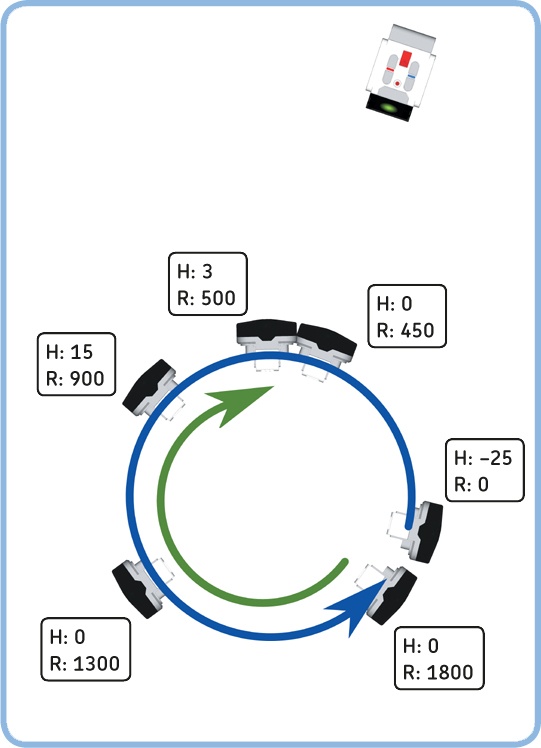
Figure 18-10. As the robot turns left (blue arrow), the Infrared Sensor continuously measures the Beacon Heading value, but this diagram shows only six measurements. If we ignore 0 values, the lowest absolute heading value (H) is 3 in this case. At this position, the Rotation Sensor value of motor C (R) is 500 degrees. When the robot completes the circle (when the Rotation Sensor measures 1800 degrees), the robot turns right until it measures 500 degrees again (green arrow) and the robot points (roughly) in the direction of the beacon.
By storing the Rotation Sensor value measured at the time the lowest Beacon Heading value was detected, the robot is able to return to this position later; it just has to turn to the right until motor C is back at the stored position (500 degrees in the example).
The flow diagram in Figure 18-11 shows how the robot can determine the lowest valid heading value and the corresponding Rotation Sensor value. In the diagram, the variable called Reading represents the absolute value of the Beacon Heading measurement, updated with a new measurement each time the loop repeats.
Rather than storing all measurements and picking the lowest one, the program stores only one value in a variable called Lowest. Each time a new valid reading is less than the value in Lowest, the new reading is stored in Lowest and the Rotation Sensor value is stored in a variable called Position. Ultimately, Lowest contains the lowest recorded valid sensor measurement, and Position contains the Rotation Sensor value recorded when this lowest detection was made.
You can now implement the flow diagram using the programming instructions shown in Figure 18-12 through Figure 18-16. You’ll implement the two questions in the flow diagram using Switch blocks, marked a and b respectively.
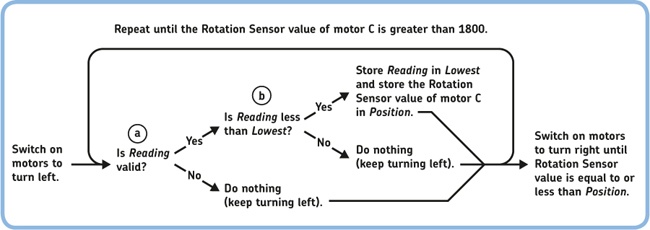
Figure 18-11. The search algorithm. The Reading variable contains the absolute value of the Beacon Heading and is considered valid if it isn’t 0.
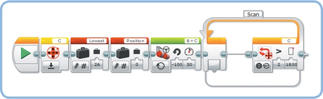
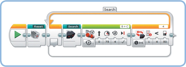
Figure 18-12. Step 1: Define two Numeric variables called Lowest and Position, and initialize them as shown. Initialize Lowest to 26 so that any successful measurement (25 or less) will be the next lowest value. Also, reset the Rotation Sensor of motor C, switch on the motors to turn left, and add the Loop block you’ll use to scan for the beacon. The loop runs until motor C has turned 1800 degrees. (This should result in the robot turning roughly 360 degrees.)
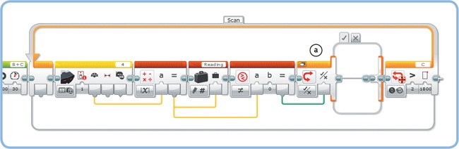
Figure 18-13. Step 2: Now add the blocks to the loop that make the robot store one measurement, take its absolute value, and determine whether it’s nonzero. Define a Numeric variable called Reading, and configure the blocks as shown. You use the Compare block to check whether the value is nonzero, and the blocks on the true tab of the Switch block (a) will run if this is the case. Nothing should happen if the value is zero, so the false tab should remain empty.
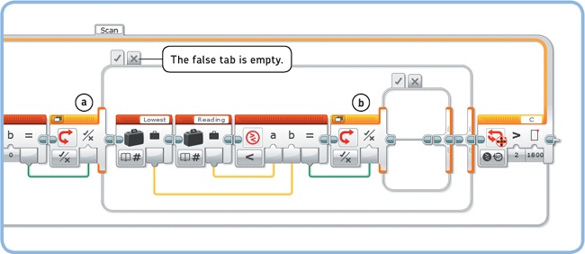
Figure 18-14. Step 3: Now that you have a valid measurement, you can compare it to the lowest value recorded so far (a). If Reading is less than Lowest, the output of the Compare block is true, and the blocks on the true tab of the Switch block (b) will run.
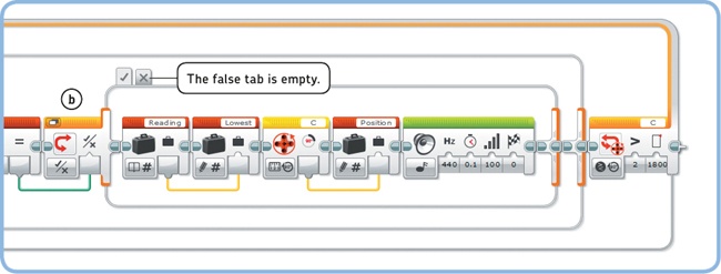
Figure 18-15. Step 4: Now that you know that the new value in Reading is less than Lowest, you store Reading in Lowest, and you store the current Rotation Sensor value in Position. You add the Sound block so that you hear a beep each time the robot updates Lowest and Position with new values. Nothing should happen if the new Reading is not less than Lowest, so the false tab should remain empty.

Figure 18-16. Step 5: Having completed its full turn to the left, the robot should now turn right until the Rotation Sensor is back at the point where the lowest measurement was detected (the value stored in Position). The motors are switched off, and the robot should now face in the direction of the beacon.

When you’re ready, turn all the blocks into a My Block called Search, as shown in Figure 18-17.
Place the IR bug about 1 meter (3 feet) away from the robot, and make the beacon continuously send a signal by pressing the button at the top of the remote (Button ID 9). The robot can face in any direction when the program begins, but the infrared beacon should point toward the robot, as shown in Figure 18-18. If the grabber is not in the reset position with its claws open, run the Reset My Block you made earlier.
Now run the Search My Block to test it. The robot should turn around and beep each time it sees a lower measurement than the previously stored lowest value. After making one complete turn to the left, it should turn to the right until it faces the beacon. This should be the point where you last heard the robot beep. If the robot isn’t successful on its first try, place the IR bug closer to the robot and run the Search My Block again.
The final program will make the robot search for the IR bug, drive toward it, grab and lift it, move it to a new position, and then lower and release it. To begin, create a new program called Autonomous and implement each of these actions using the instructions that follow.
Discovery #119: Signal Verification!
If you forget to switch on the infrared beacon, the robot won’t detect a signal at all. Can you add blocks at the end of the Search My Block that make the robot say “Error” if the robot wasn’t able to get the beacon’s direction any time during the loop?
Hint
If the robot didn’t detect anything during the loop, what value will be stored in Lowest after the loop completes? Look for the answer in Figure 18-11 and Figure 18-12.
The first part of the program will make the SNATCH3R search for the beacon with the Search My Block and then drive forward to approach it. The robot will continue to search and drive forward until the beacon proximity is less than 50%, indicating that the beacon is nearby, as shown in Figure 18-19.
Once the beacon is in sight, the robot can drive toward it by going forward while adjusting its steering to the Beacon Heading value. Rather than using a fixed steering setting, as you did in Chapter 8, you’ll make the amount of steering proportional to the Beacon Heading. The farther the beacon is to the left, the more the robot steers left; the farther the beacon is to the right, the more the robot steers right.
Because the previous search loop ended only once the beacon proximity was less than 50%, you know that the robot faces at least roughly in the direction of the beacon. Therefore, 0 values should indicate that the beacon is right in front of the robot, and you no longer have to ignore them. In fact, because steering is proportional to the heading, steering will be 0 if the heading is 0, and the robot will drive straight ahead.
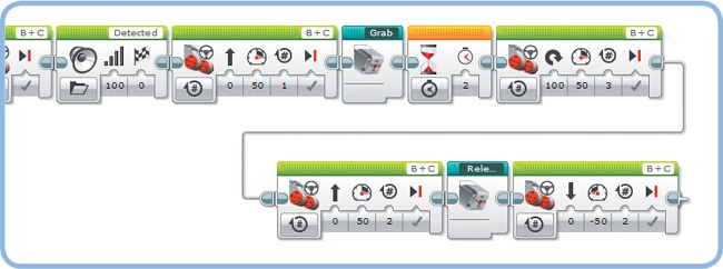
The robot will continue to adapt its steering setting until the beacon proximity is 1%, when the IR bug is nearly positioned between the robot’s claws, as shown in Figure 18-20. Test this section of the program by selecting only the Loop block and clicking the Run Selected button.
The robot is almost ready to grab the beacon, but first it drives forward for one more rotation to ensure the IR bug is properly positioned between the robot’s claws. Once the grabber is raised with the Grab My Block, the robot turns around, drives forward for a short while, and then lowers and releases the object in a different position with the Release My Block, as shown in Figure 18-21. When you’re ready, run your program to see how well the SNATCH3R can autonomously find the IR bug.
You’ve just completed one of the most complex robots in this book. Congratulations! In this chapter, you’ve seen how you can combine many advanced building and programming techniques to create a truly autonomous robot. Now that you’ve built and programmed the SNATCH3R, see what else you can do with this robot. To get started, explore some of the Discoveries that follow to put your robotics skills to the test.
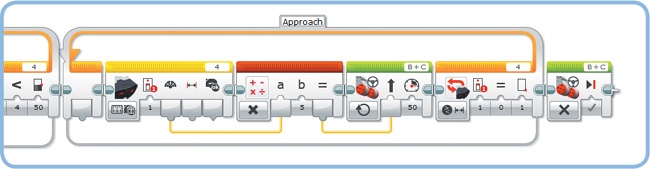
Figure 18-20. Step 2: Driving forward while adjusting the steering to the Beacon Heading value until the beacon is between the robot’s claws
Discovery #120: Keeping Busy!
Can you expand the Autonomous program so that the SNATCH3R repeatedly finds and moves the IR bug? Make the robot drive away from the object after it’s released it, search for it again, and so on. If the SNATCH3R doesn’t properly release the IR bug before driving away, program the robot to zigzag while moving backward to shake off the object.
Discovery #121: Path Finder!
The Color Sensor in the base of the SNATCH3R enables the robot to see the color of the surface beneath it in order to follow lines. Can you make the robot follow the lines of a custom track, grab an object at the end of the line, and then return it to the start of the line?
Tip
The test track you made in Chapter 7 (see Figure 7-4) might not work very well because the SNATCH3R’s treads can tear the soft paper apart. To solve this problem, glue the track to a tough piece of cardboard or create your own track on a sheet of plywood with black tape or a marker. Alternatively, you can use the Mission Pad and use the colored landmarks to design your own mission.
Discovery #122: Proximity Finder!
Can you make the SNATCH3R autonomously find objects other than the infrared beacon, such as an empty water bottle? Use the infrared proximity measurement to detect the object closest to the robot. Then make the robot drive toward the object and grab it.
Design Discovery #29: Excavator!
Can you build a robotic excavator? Remove the robotic arm from the SNATCH3R so that only the base remains (see building the SNATCH3R). Use the Medium Motor to control the arm and the digger.