You’ve already learned a lot about programming robots, but learning to build robots is just as important. Building experience comes with practice, but this part of the book aims to give you a solid introduction to building robots with your EV3 set. In this chapter, you’ll begin looking at how you can create sturdy structures for your robots using beams, frames, pins, connector blocks, and axles, as shown in Figure 10-1. You’ll also learn how the LEGO unit grid can help you design your own constructions of beams and connector blocks. In Chapter 11, you’ll learn how gears work.
Each of the examples presented in this chapter can be built using the pieces in your EV3 set, though not all at the same time. Try out the examples to get a sense of how sturdy each construction is and which ones will be useful for your robots.
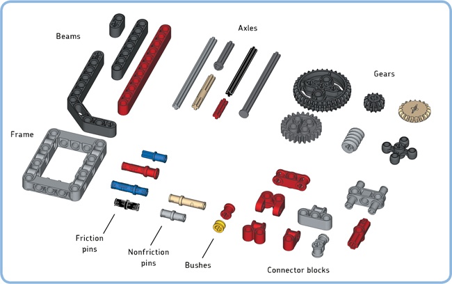
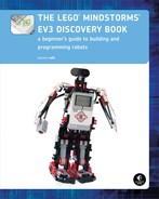
Figure 10-1. The EV3 set contains many different beams, frames, axles, gears, connector blocks, and pins. (You can find a complete parts list on the back inside cover.)
Note
You can take apart the EXPLOR3R robot if you like; you no longer need it to follow along with the rest of the book.
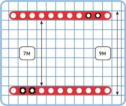
So far you’ve learned a lot about using motors, sensors, and the EV3 brick in your robots. You use beams to create structures that hold all of these elements together. The length of beams and other elements is measured in LEGO units, sometimes called modules, as shown in Figure 10-2. The shortest straight beam in the EV3 set is two LEGO units in size, or 2M; the longest beam is 15M.
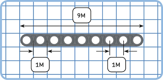
Figure 10-2. The length of beams and other elements is measured in LEGO units. The distance between the center points of two holes is exactly one LEGO unit, or 1M. Consequently, the distance between the center points of the leftmost hole and the rightmost hole of this 9M beam is 8M.
You can extend beams in length or width by joining multiple beams using friction pins. You’ll need at least two pins for a rigid connection, and it’s best to have at least three holes overlap, as shown in Figure 10-3.

The EV3 set contains two types of frames, as shown in Figure 10-4. Frames make it easy to create large structures with many attachment points for other elements, such as beams and motors. Frames are also useful for connecting beams at a right angle.

Beams are useful not only to create new structures but also to reinforce, or strengthen, existing structures. For instance, consider the top structure consisting of two frames in Figure 10-5. It’s easy to pull the two frames apart because doing so breaks only two pin connections.
The bottom structure is reinforced with two 3M beams, making it very hard to pull the two frames apart. (You could make the structure even stronger by replacing the 3M beams with 11M beams that span the full width of the frame.)

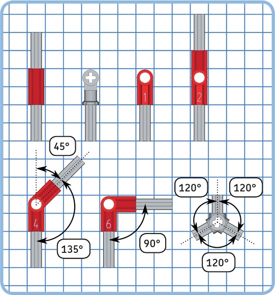
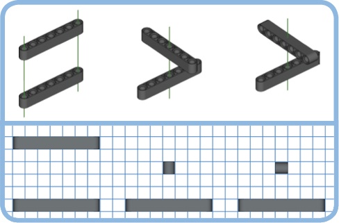
The EV3 set contains many angled beams of different types and angles. The set contains four types of angled beams with a 90-degree angle, or right angle, as shown in Figure 10-6. You’ll use these beams to join straight beams at a right angle.
In addition to right-angled beams, your set contains two types of beams with a 53.13-degree angle, as shown in Figure 10-7. This might seem like a strange angle, but it’s actually quite useful because it can form the corner of a certain common triangle. Specifically, you can use this angle to create a Pythagorean (right-angled) triangle whose sides are 3M, 4M, and 5M, as shown in Figure 10-8.

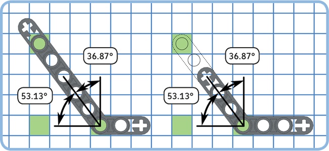
Figure 10-7. Two beams with a 53.13-degree angle. Because the angles of both beams are the same, you can extend the shorter one (right) with a straight beam to achieve similar building possibilities to those provided by the larger one (left).

Figure 10-8. Creating two of the same right-angled triangles with straight beams (left) and with angled beams (right). The pins aren’t actually green, but they are colored to match the connection points marked in green in Figure 10-7. Note that the triangle sides are measured between the center points of the holes at each corner instead of by counting the number of holes on the beam.
Discovery #54: Bigger Triangles!
There is another useful right-angled triangle that you can build using the elements in the EV3 set. In fact, it is twice the size of the triangle shown in Figure 10-8. Can you build this triangle? What about a triangle that is three times the size?
The left of Figure 10-9 is a grid of 1M-sized squares. This LEGO unit grid can help you design sturdy robots in a structured way. If you attach new elements to the beams so that their holes align with this grid, it will be easier to add more elements later (a).
If you stray off the grid by placing pieces at an angle, connecting more elements becomes difficult because LEGO parts come only in a limited number of fixed sizes (b). This type of construction is not recommended for the main structure of your robot, though it may be fine for decorative parts, such as the tail of an animal robot.
Building off the grid can cause beams to stretch or bend and damage your LEGO elements (c). You should always avoid this type of construction. In general, avoid connections that you can’t make without bending or stretching elements slightly. If you’re not sure whether an angled construction causes pieces to bend or not, it’s best to stick to the unit grid by using right angles.
You can stay on the grid with 53.13-degree angled beams by using the connection holes marked green in Figure 10-7. In this way, you can use angled beams to build right-angled constructions, as shown in Figure 10-10.
Note
You can print a copy of the LEGO unit grid from http://ev3.robotsquare.com/grid.pdf to use as a reference for your own designs. Be sure to select actual size, or 100%, in the print size settings. The 15M beam on the printed chart should be the same size as an actual 15M beam. If it’s not the same size, try adjusting the scale setting and print the grid again.

Figure 10-9. Building on the grid is recommended (a). You can build off the grid if necessary (b) as long as you do not stress the beams to make them fit (c).
Discovery #55: Angled Combinations!
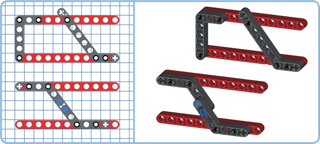
Can you find a combination of two 53.13-degree angled beams to connect the two parallel 11M beams shown in Figure 10-11?
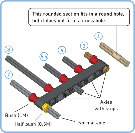
An axle is a shaft to which you can mount rotating elements, like wheels or gears. Axles spin freely in round holes, but you can use them to create rigid connections by mounting them in cross holes, as shown in Figure 10-12. The shortest axle in the EV3 set is 2M; the longest axle is 9M.
You can prevent an axle from falling out of a round hole by adding a bush to secure it or by using an axle with a stop, as shown in Figure 10-13.
The axle pin with friction, shown in Figure 10-14, is a useful connector. One end is a pin with friction, which can be mounted in a round hole, where it will spin with some resistance. The other end is an axle, which can be mounted in a cross hole, where it will remain stationary. Some LEGO sets contain a similar tan or grey axle pin without friction; its pin rotates smoothly in a round hole.

You use connector blocks to join beams, axles, motors, and sensors at various angles. Each type of connector block in the EV3 set can be used in many ways, but this section provides some useful examples to get you started.
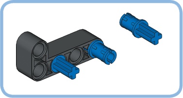
Some connector blocks can be used to extend two axles, as shown in Figure 10-15. Doing so allows you to join two axles at an angle or combine axles to make them longer.
You can use frames or beams to connect two parallel beams, but you can also use a combination of connector blocks, as shown in Figure 10-16 and Figure 10-17. This is useful when space is limited or when you’ve run out of beams or frames. Use the unit grid as a reference for your own designs. For example, if you need to bridge a 3M gap between two parallel beams, you can use option f in Figure 10-16.
In Figure 10-16 through Figure 10-18, you’ll see how to combine certain connectors on the left, and you’ll see examples of these combinations in use on the right.
Many connector blocks have round holes or cross holes positioned perpendicular to one another. This makes it possible to connect beams at a right angle or to connect parallel beams whose holes are placed perpendicular to one another, as shown in Figure 10-18.
You’ve seen earlier that you can strengthen structures using beams (see Figure 10-5). But depending on the orientation of the beam holes, you may need to add connector blocks before you can add beams for reinforcement, as shown in Figure 10-19.

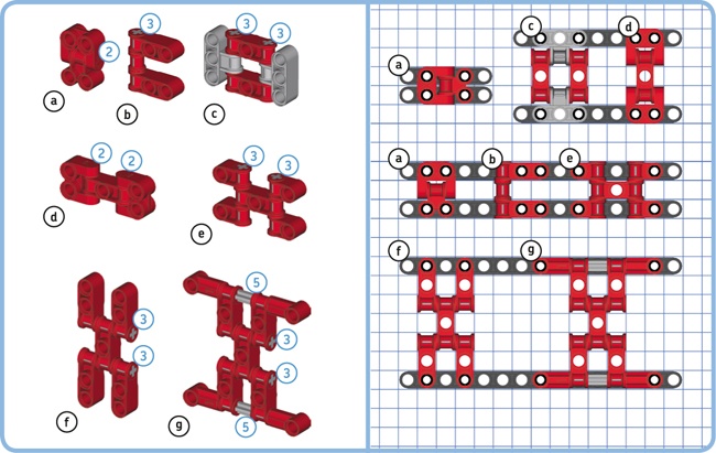
Figure 10-17. Connecting parallel beams with their flat sides facing each other. The circled numbers denote the length of the axles used in the constructions.
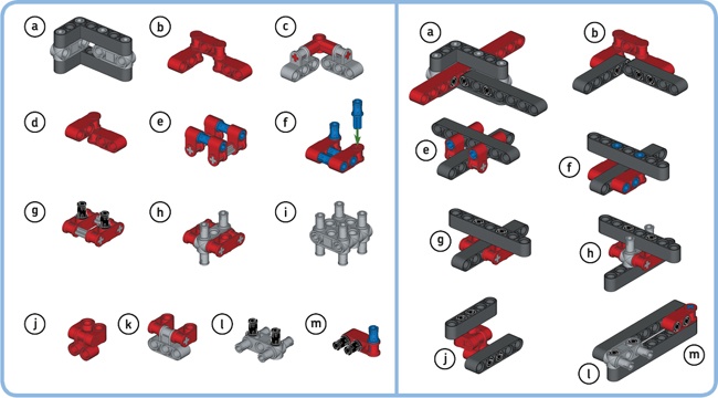
Figure 10-18. Using connector blocks to connect beams at a right angle. Each of the grey axles are 3M in size.
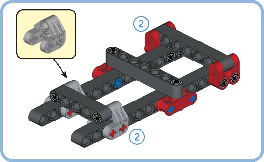
Figure 10-19. You can use connector blocks to create attachment points for beams that reinforce a construction. Note that these structures aren’t rigid when used on their own; you should use these techniques to strengthen structures like the ones in Figure 10-16.
Discovery #56: Constructive Connectors!
Can you combine connector blocks to make sturdy connections between beams, as shown in Figure 10-20? Expand the examples from Figure 10-16 through Figure 10-19 or create your own combinations.
Certain combinations of connector blocks result in a 0.5M offset from the unit grid, as shown in Figure 10-21. When used properly, this technique gives you more building options without compromising sturdiness. For example, you can create constructions that are 7.5M in size rather than 7M or 8M.
Note that you cannot easily strengthen such structures with beams because the distance between two beam holes should always be a whole number. That is, in this particular construction, you can’t use a beam to connect the top beam to the one in the middle.

Figure 10-21. Some combinations of connector blocks result in a 0.5M offset from the unit grid. The beam in the middle has a 0.5M offset relative to the other two beams.
Discovery #57: Half-Unit Beams!
Can you join two beams to create an 18.5M beam using connector blocks?
Hint
Use the connector blocks that are shown in Figure 10-21.
Most of the elements in the EV3 set are exactly 1M in width, but some thin elements are just 0.5M wide, as shown in Figure 10-22. Thin elements can be used when there is no space for larger elements. (The EV3 set does not contain many thin elements; you’ll need to use thin elements from other LEGO Technic sets to take full advantage of this technique.)
One element to highlight here is the cam, which is especially useful for creating a rotating mechanism that presses the Touch Sensor once per rotation, as you’ll see in Chapter 13.

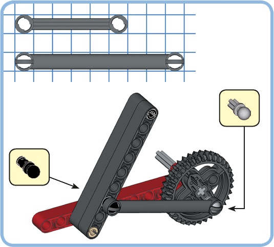
You use nonfriction pins (the grey and tan pins in the EV3 set) to create hinges and flexible mechanisms instead of rigid constructions. For example, the nonfriction pins in the mechanism of Figure 10-23 make it easy to turn the gear.
The EV3 set contains two types of steering links (6M and 9M), normally used for steering mechanisms in LEGO Technic cars. These links can be used to replace beams in certain constructions. While a link creates a less sturdy connection than a beam, it can be used to connect elements that are not in the same plane. That is, if you widen the moving beam of the previous mechanism, you cannot use a beam to connect it to the gear, but you can use a steering link, as shown in Figure 10-24.

We’ll now look at how you can employ the size and shape of motors to use them as central components of your robots. Because motors are large and have many attachment points for pins and axles, it’s often practical to use a motor as a starting point for a mechanism such as a robotic claw or a tank drive.
This method makes it possible to test each mechanism, or module, on its own. Once you’ve verified that all of the modules work well on their own, you can combine them into a single, sturdy robot.
The geometry of the Large Motor (see Figure 10-25) makes it easy to connect two motors using a frame and friction pins. Doing so gives you a head start in creating a vehicle robot, as shown in Figure 10-26. All you need to do is add wheels or treads and the EV3 brick.
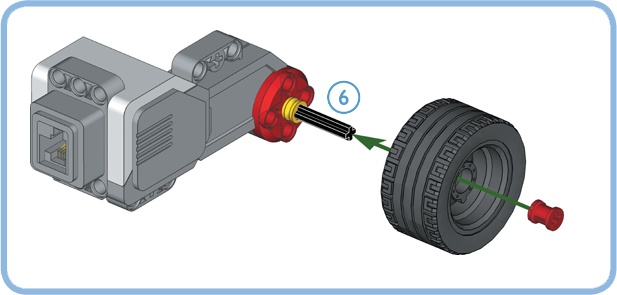
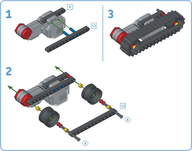
The Large Motor is strong and fast enough to drive wheels directly, as shown in Figure 10-27. You can also directly drive tank treads by bracing them with two 13M beams. Figure 10-28 shows the essential geometry, and you’ll see another example when building the SNATCH3R in Chapter 18. (You’ll learn how to connect gears to the Large Motor in the next chapter.)

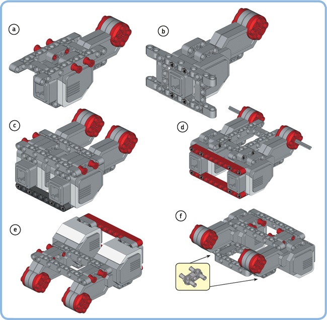
Figure 10-26. Adding frames to a motor makes it easier to mount the motor in a robot. For example, you can create a base for a vehicle robot by joining two Large Motors using frames, beams, and friction pins in various ways.
You can connect wheels and gears to the red motor shaft on the Large Motor using the cross hole, but you can also make beams and other elements rotate by connecting them to the round holes on the shaft. For example, you can make the motor continuously rotate a 3M beam to create a reciprocating mechanism, as shown in Figure 10-29.

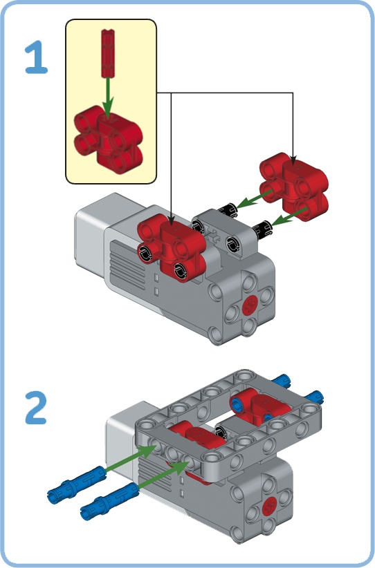
The Medium Motor (see Figure 10-30) is more compact than the Large Motor, allowing you to use it in small mechanisms, such as the steering mechanism of a race car. The motor has round mounting holes near the front, and you can create more connection points in the back by adding a frame, as shown in Figure 10-31. You can also add a frame as shown in Figure 10-32 so you can mount it between the two Large Motors of a vehicle robot, for example, to motorize a forklift mechanism.
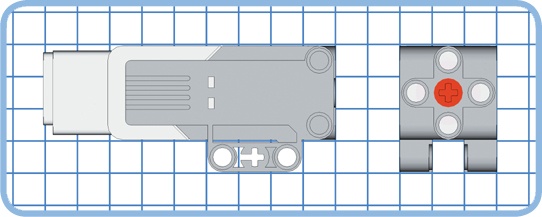

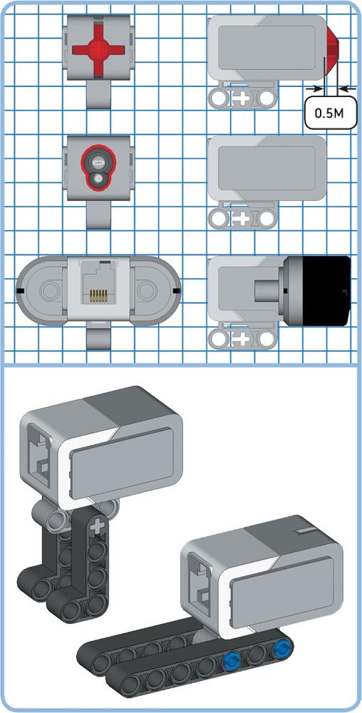
Each of the sensors in the EV3 set has attachment points for one axle and two pins, as shown in Figure 10-33. In addition, the Infrared Sensor has two round holes in the back. To create a rigid connection, you’ll need to use either two pins and a beam or an axle and a beam with a cross hole.
In addition to the pieces discussed in this part of the book, the set contains various other elements, such as swords and monster teeth, which you can use to decorate your robots. Finally, your set includes a ball shooter and ball magazine component. You can find instructions on how to build a shooter with these components by following the building steps for EV3RSTORM in the EV3 software (see Figure 3-2).
In this chapter, you’ve learned the essentials of using beams, frames, pins, axles, connector blocks, and motors to create components for your robots. You’ve also learned how the LEGO unit grid can help you design your own sturdy constructions. There is no recipe for creating a perfect robot. Instead, the best way to gain experience in designing your own robots is just to try things out. You can begin by building the designs presented in this book and then modify them to create your own robots using the Design Discoveries throughout.
In the next chapter, you’ll look at how gears work and how you can use them with the EV3 motors.
Design Discovery #12: Tank Drive!
The EXPLOR3R moves around on two wheels and a support wheel in the back. Can you create a version of the EXPLOR3R that drives around on tank treads? Test your creation by driving it around with the infrared remote.
Hint
Use the tank tread example in Figure 10-28. Why should you remove EXPLOR3R’s support wheel?
Design Discovery #13: Tabletop Cleaner!
Can you create a robot that drives around a tabletop without driving off the table? Make the robot sweep away any LEGO elements in front of it with the Medium Motor so the robot cleans the tabletop as it drives around.
Add the Infrared Sensor to the front of the robot, about 25 cm (10 inches) ahead of the robot’s front wheels, and make it point downward so it sees the tabletop. How do you make the robot detect the approaching table edge?
Tip
If you’ve already built the robot from Design Discovery #12 in Design Discovery #12: Tank Drive!, you can use it as a starting point for this Design Discovery.
Design Discovery #14: Curtain Opener!
Can you design a robot that automatically opens the curtains when the sun rises and closes the curtains when the sun sets? Use the Color Sensor to measure the ambient light intensity, and add an option to override the automatic behavior with the infrared remote control.