In this fifth part of the book, you’ll learn how to use data wires (this chapter), Data Operations blocks (Chapter 15), and variables (Chapter 16) to create more advanced programs for your robots. Chapter 17 demonstrates how you can combine these techniques to create a larger program that lets you play an Etch-A-Sketch-like game on the EV3 brick. You’ll do all this with a robot called SK3TCHBOT, shown in Figure 14-1.
In earlier chapters, you configured programming blocks by entering the desired settings of each block manually. One of the fundamental concepts in this chapter is that blocks can configure each other by sending information from one block to another with a data wire. For example, one block can measure the Infrared Sensor’s proximity value and send it to a Large Motor block. The Motor block can use the received value to set the motor’s speed. As a consequence, the motor moves slowly for low sensor values (27% proximity results in 27% speed) and quickly for high sensor values (85% proximity results in 85% speed).
This chapter teaches you how to make programs that use data wires. You may find this a bit difficult at first, but as you go through the sample programs and the Discoveries, you’ll master all of these programming techniques!
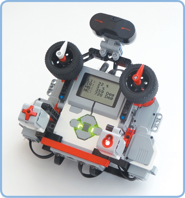
Figure 14-1. You’ll use SK3TCHBOT to learn many new programming techniques and to play an Etch-A-Sketch-like game on the EV3 screen.
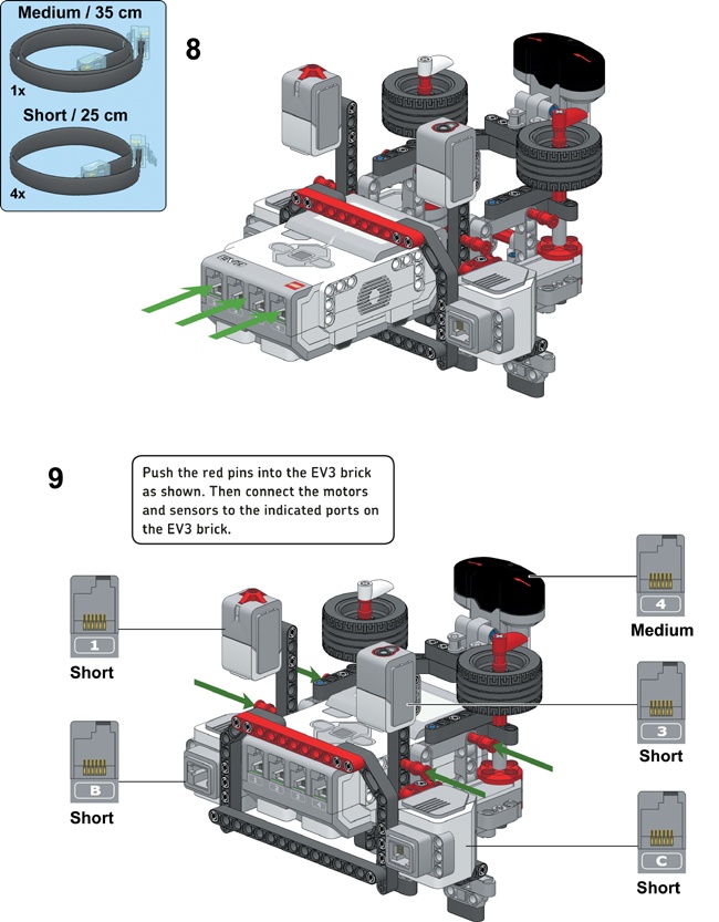
You’ll use SK3TCHBOT to test your programs with data wires and variables. The robot consists of the EV3 brick, three sensors, and two Large Motors, which you’ll use as inputs and outputs for your programs so you can see data wires in action. In Chapter 17, you’ll learn how to create a program that turns SK3TCHBOT into an Etch-A-Sketch-like device, letting you make drawings on the screen by turning the input dials attached to the motors.
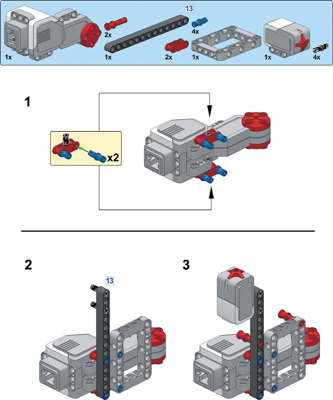
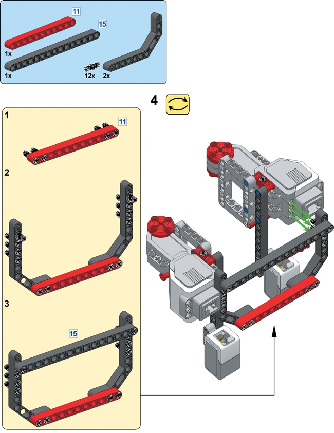
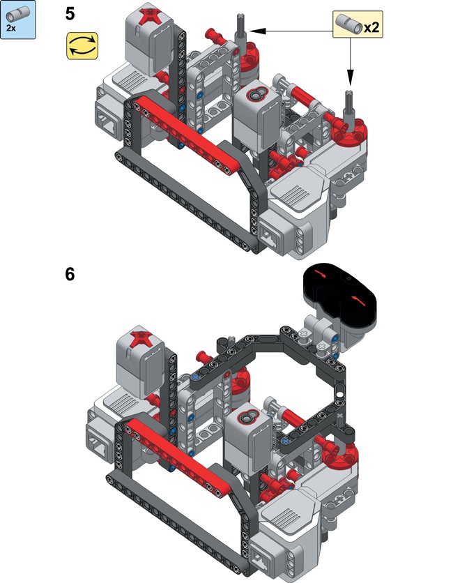
Build SK3TCHBOT by following the instructions on the next pages, but first select the required pieces, as shown in Figure 14-2.


To see how data wires work, you’ll create a small program that makes SK3TCHBOT play a sound and then rotate the white dial for 3 seconds. The motor’s Power setting, and therefore its speed, will respond to what the Infrared Sensor sees: If the sensor’s proximity value is 27%, the motor’s speed will be 27%; if the sensor reads 85%, the motor’s speed will be 85%; and so on.
You use the Infrared Sensor block to read the sensor. (You’ll learn more about Sensor blocks later.) Create a new project called SK3TCHBOT-Wire with a program called FirstWire, as shown in Figure 14-3 and Figure 14-4, and download it to your robot.
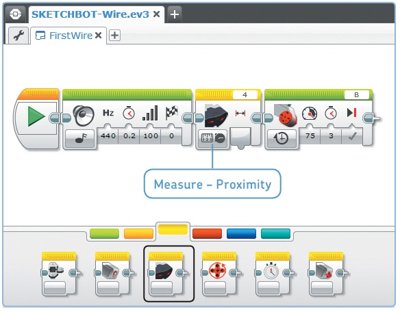
Figure 14-3. Step 1: Place all the necessary blocks on the canvas, and configure them as shown. You’ll find the Infrared Sensor block on the yellow tab of the Programming Palette. Be sure to select Measure – Proximity mode.
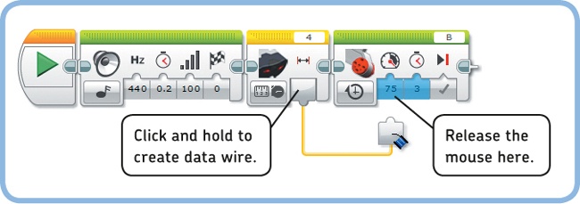
Figure 14-4. Step 2: Create and connect the yellow data wire as shown. Then run the finished program.
You should notice that the white dial turns at a different speed each time you run the program. For example, if you hold your hand close to the sensor and run the program, the wheel should spin slowly, but it should spin faster if you run the program again with your hand farther away.
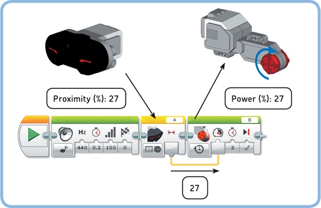
Congratulations! You’ve just created your first program with data wires. Let’s have a look at how each block works. The first Sound block simply plays a sound. Once the sound finishes playing, the Infrared Sensor takes one measurement (let’s say it reads a proximity value of 27%). The yellow data wire carries the sensor measurement to the Large Motor block, which then makes motor B turn for 3 seconds. The Power setting of the Large Motor block depends on the value carried by the data wire; it’s 27% in this case. Figure 14-5 shows an overview of what happens.
Discovery #73: Sound in the Distance!
Remove the Large Motor block from the FirstWire program, and replace it with a Sound block configured to say “Hello.” Connect the data wire from the Infrared Sensor block to the Volume input of the Sound block. This should make the robot say “Hello” softly when it sees you up close or loudly when it sees you from afar.
As you’ve seen, you use a data wire to carry information between blocks. The information is always sent from an output plug to an input plug, as shown in Figure 14-6. In the example program, the data wire carries the sensor value from the Sensor block’s Proximity output plug to the Motor block’s Power input plug.
Note that the data wire hides the value that you originally entered in the Power setting (75). The program ignores this value and uses the value it gets from the data wire instead. On the other hand, because you didn’t connect data wires to the other input plugs of the Motor block (Seconds and the Brake at End), they operate normally. For example, you entered 3 in the Seconds setting, making the motor rotate for 3 seconds.
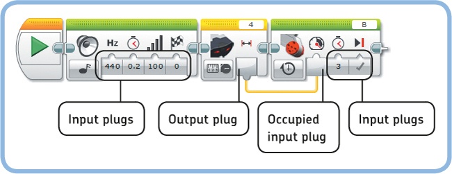
Figure 14-6. The data wire carries information from an output plug (on the Infrared Sensor block) to an input plug (on the Large Motor block).
Now let’s have a look at some other properties of data wires.
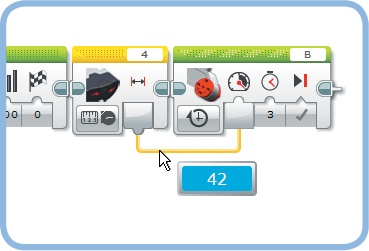
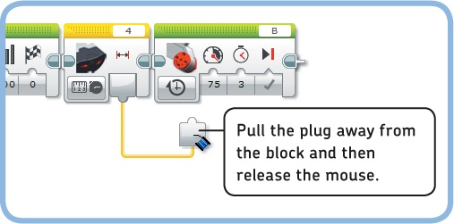
You can see the value carried by a data wire by placing your mouse on the wire while the program runs, as shown in Figure 14-7. This can help you understand exactly what’s going on in your program.
You’ll see data wire values only if the robot is connected to the computer and you launch the program using the Download and Run button in the EV3 software; you won’t see them if you start the program manually using the EV3 buttons.
Delete a data wire by disconnecting the right end, as shown in Figure 14-8.
When configuring programs with data wires, you don’t have to connect a block to the one right next to it; you can connect blocks when there are other blocks in between, as shown in Figure 14-9. The WirePause program reads the sensor, pauses for 5 seconds, and makes the motor move. The motor speed is based on the sensor measurement taken at the start of the program.
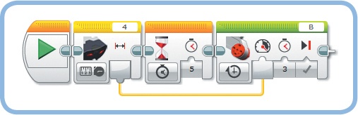
Figure 14-9. The WirePause program takes one measurement when the Sensor block runs (say, 34%). After 5 seconds, the motor begins turning at 34% speed, even if the sensor value has changed in the meantime.
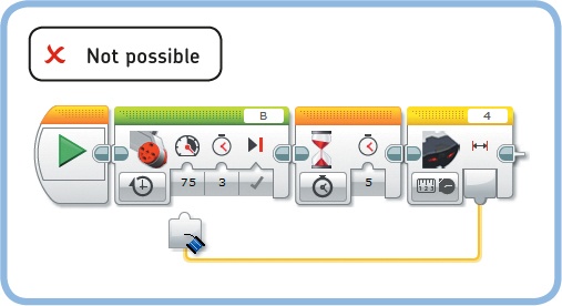
The reverse isn’t possible, as shown in Figure 14-10. You can’t make the Motor block use the data wire because the wire doesn’t contain a value until the measurement is made. In other words, the block with the input plug (the Motor block, in this case) must come after the block with the output plug (the Sensor block).
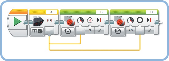
You can use an output plug as a starting point for multiple data wires, as shown in Figure 14-11. The MultiWire program sends the proximity measurement to the Power setting of the motor on port B (white dial) and to the Degrees setting of the motor on port C (red dial). For example, if the sensor measurement is 34%, motor B rotates at 34% speed while motor C rotates 34 degrees at 75% speed.
On the other hand, you can’t connect multiple data wires to a single input plug. Once an input is occupied (see Figure 14-6), you can’t connect another wire to it. (If it were possible to connect two or more wires to the same input, the block wouldn’t know which of the values to use.)
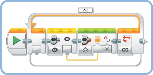
In the FirstWire program, the motor moved for 3 seconds at a constant speed based on one sensor value taken just before the motor started moving. You’ll now expand this program to make the motor adapt its speed to the sensor value continuously. To do so, place the Sensor block and the Motor block in a Loop block, and set the mode of the Large Motor block to On, as shown in Figure 14-12.
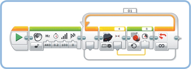
Figure 14-12. The RepeatWire program continuously adapts the motor’s speed to the proximity sensor measurement.
When you run the RepeatWire program, the motor’s speed should change gradually as you slowly move your hand away from the sensor. If you suddenly place your hand up close to the sensor, the sensor value drops and the motor quickly stops.
The speed changes continuously because the blocks in the loop take hardly any time to run. The Sensor block takes a measurement, and the Motor block switches on the motor at the desired speed. Then, the program goes back to run the blocks in the loop again, instantly taking a new measurement to adjust the speed, and so on.
Discovery #74: Bar Graph!
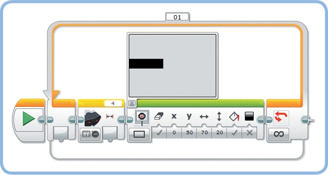
The incomplete program shown in Figure 14-13 plots a bar graph on the EV3 screen, but a data wire is missing. How do you connect the data wire to make the bar’s length represent the proximity measurement?
Discovery #75: Extended Graph!
Expand the program you made in Discovery #74 in Discovery #74: Bar Graph! by adding two more bar graphs representing the reflected light intensity and the ambient light intensity as measured by the Color Sensor.
So far you’ve used data wires to transfer numerical values only, but there are three basic types of information that data wires can carry: Numeric, Logic, and Text. Each type has its own color and plug shape (round/yellow, triangular/green, and square/orange), as shown in Table 14-1. The plug shape matches the shape of the input it connects to like a puzzle piece. This match helps indicate what data wire type can be connected to a particular input.


The Numeric data wire (yellow) carries numeric information that may include whole numbers (such as 0, 15, or 1427), numbers with decimals (such as 0.1 or 73.14), and negative numbers (such as –14 or –31.47). The Infrared Sensor’s proximity is an example of such a numeric value (it ranges between 0 and 100).
The Logic data wire (green) can carry only two values: true or false. These wires are often used to define settings of a block that can have only two values, such as the Clear Screen setting of the Display block. Similarly, because the Touch Sensor has only two possible values (pressed and released), it uses a Logic data wire to send the sensor state. The Touch Sensor block in Measure – State mode gives you a Logic data wire carrying true if the sensor is pressed and false if it’s not pressed.
Create the LogicClear program to see a Logic data wire in action, as shown in Figure 14-14. The program begins by displaying an image of two angry eyes on the EV3 screen. Two seconds later, the robot determines the Touch Sensor value and passes it to the Clear Screen setting of the Display block with a Logic data wire. If the sensor is pressed (true), the screen is cleared before displaying the word MINDSTORMS. If it’s not pressed (false), the screen isn’t cleared and the word is simply drawn on top of the image.
The Text data wire (orange) carries text to, for example, a Display block so that it appears on the EV3 screen. Text can be a word or phrase, like Hello, I’m a robot, or 5 apples. We’ll get back to this data wire type in Chapter 15.

In addition to the Numeric, Logic, and Text data wire types, the EV3 software has the Numeric array and the Logic array data wire types. A Numeric array is basically a list of Numeric values used to send multiple numbers across a single wire. For example, you could use an array to send the five most recent sensor values to a custom My Block that displays all of them on the EV3 screen.
Similarly, a Logic array is a list of Logic values. We won’t use arrays here, but you can experiment with an example program that uses arrays at http://ev3.robotsquare.com/ after you’ve finished reading this book.


Generally, you should connect Numeric data wires to inputs that accept numeric values (rounded plug), Logic data wires to logic inputs (triangular plug), and Text data wires to text inputs (square plug).
However, the EV3 software allows three more connections, as shown in Table 14-2. You can remember which connections work by looking at the shape of the plugs. In some cases, the shapes don’t match exactly, but they still fit. For example, the triangular plug fits in a rounded socket, which means you can control a Numeric input with a Logic data wire. On the other hand, a rounded plug doesn’t fit in a triangular socket, which means you can’t control a Logic input with a Numeric data wire.
In the three situations shown in Table 14-2, the information carried by the wire is converted to the proper type to make your program work. Let’s make two programs to see what this means.
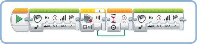
The ConvertWire program (Figure 14-15) demonstrates the conversion of a Logic value to a Numeric value. The Wait block requires a numeric value for the Seconds setting, but it receives a Logic value from the Touch Sensor block instead. This works because the software converts the Logic value to a Numeric value: True becomes 1; False becomes 0. Consequently, you’ll hear a 1-second pause between the beeps if you press the sensor, but you’ll hear no pause (0 seconds) if the sensor isn’t pressed.
When using a Display block to display text on the EV3 screen, you can either type something in the Text field or select Wired, as shown in Figure 14-16. Selecting Wired creates an extra input plug, allowing you to supply the text with a data wire.
The block expects you to connect a Text data wire to the Text input, but you can also connect a Numeric data wire. Computers like the EV3 brick store numbers and text lines in two different ways. Therefore, you normally can’t send a Numeric value to a Text input. Fortunately, the software converts the number to a text format that the Display block understands. This conversion makes it possible to display numbers on the EV3 screen, as demonstrated by the DisplayNumeric program (see Figure 14-17).
The program continuously updates the sensor value and shows it on the screen. Displaying values is a useful technique to test your programs. Of course, you already know how to monitor sensor values with Port View, but with this data wire technique, you can also perform calculations on sensor values and display the results in real time, for example, as you’ll see in the next chapter.
In addition to Text and Numeric data wires, a Text input plug can accept Logic data wires. Again, the EV3 brick stores Logic values in a different way, but the program converts them to a Text format when necessary. True causes the Display block to display 1, while false makes the block display 0. Replace the Infrared Sensor block in the DisplayNumeric program with a Touch Sensor block to try this out.


In Part II, you learned to work with sensors by creating programs with the Wait, Loop, and Switch blocks. The final way to read sensors is with Sensor blocks. These blocks are useful if you want to retrieve a sensor value and transfer it to another block with a data wire, as you saw with the FirstWire program.
There’s a Sensor block for each sensor on the Sensor tab of the Programming Palette, as shown in Figure 14-18. Each block can be used in Measure mode or Compare mode.
A Sensor block in Measure mode takes one measurement and passes the measured value on to another block with a data wire. You choose the type of measurement by selecting one of the sensor’s operation modes. For example, you passed the proximity sensor value to a Motor block using an Infrared Sensor block in Measure – Proximity mode.
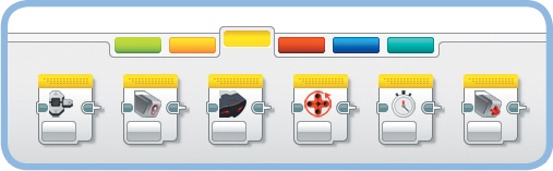
Figure 14-18. From left to right: Brick Buttons block, Color Sensor block, Infrared Sensor block, Motor Rotation block, Timer block, and Touch Sensor block
Everything you have learned about sensor operation modes and sensor values so far holds true for Sensor blocks, too. Table 14-3 provides a summary of the sensor values for each sensor operation mode. Use this chart as a reference when making your own programs, whether you use Wait, Loop, Switch, or Sensor blocks.
Table 14-3. sensor values for each sensor operation mode
Sensor block | Operation mode | Min. | Max. | Meaning | Page | Notes |
|---|---|---|---|---|---|---|
0 | 5 | 0 = None, 1 = Left, 2 = Center, 3 = Right, 4 = Up, 5 = Down | 97 | Detects only one button at a time. | ||
0 | 7 | 0 = No color detected, 1 = Black, 2 = Blue, 3 = Green, 4 = Yellow, 5 = Red, 6 = White, 7 = Brown | 77 | |||
0 | 100 | 0 = Lowest reflectivity 100 = Highest reflectivity | 81 | |||
0 | 100 | 0 = Darkness 100 = Very bright light | 85 | |||
0 | 100 | 0 = Very close 100 = Very far | 89 | |||
1 | 100 | 1 = Very close 100 = Very far | 93 | The value is undefined if no beacon signal is detected. See Figure 14-26. | ||
–25 | 25 | –25 = Left 0 = Middle 25 = Right | 93 | The value is also 0 if no beacon signal is detected or if the signal direction cannot be resolved. | ||
0 | 11 | The number represents a combination of pressed buttons on the remote. | 92 | |||
N/A | N/A | Number of degrees that the motor has turned since the start of the program. | 98 | The value can be reset to 0 with Reset mode. | ||
N/A | N/A | Number of rotations that the motor has turned since the start of the program. | 98 | The value is a decimal number, such as 1.5 for one and a half rotations. The value can be reset to 0 with Reset mode. | ||
–100 | 100 | The number represents the rotational speed of the motor. 100% speed is equivalent to 170 rpm for the Large Motor; 100% speed is equivalent to 267 rpm for the Medium Motor. | 99 | This mode measures rotational speed; it does not measure current or power consumption. The measured value is independent of the EV3 brick’s battery level. | ||
0 | N/A | Time elapsed in seconds since the start of the program. | 235 | The value is a decimal number, such as 1.5 for one and a half seconds. The value can be reset to 0 with Reset mode. | ||
False | True | False = Released True = Pressed | 66 | The value is carried out with a Logic data wire. |


Just as in Measure mode, a Sensor block in Compare mode takes one measurement and outputs the sensor value with a data wire. In addition, it compares the measured value to a threshold value, and it outputs the result with a Logic data wire. The Compare Result plug carries out true if the condition (for example, “The proximity value is greater than 40%”) is true; it carries out false if the condition is false. You specify the condition by entering a Threshold Value and choosing a Compare Type in the block’s settings, as you’ve done for Wait, Loop, and Switch blocks.
You’ll now create a program to see how this works. The SensorCompare program (see Figure 14-19) contains an Infrared Sensor block in Compare – Proximity mode to measure the sensor value and check whether it’s greater than 40%. The proximity value controls the speed of motor B, which runs for 5 seconds. The Compare Result output controls the Pulse setting of the Brick Status Light block. If the comparison is true (the sensor value is indeed greater than 40%), the Pulse setting will be true, making the status light blink. If it’s false, the light just stays on.

Beacon Proximity and Beacon Heading are combined into a single mode (called Beacon) if you use an Infrared Sensor block in Measure mode (see Figure 14-23). They appear as separate modes if you choose Compare mode, but otherwise there is no difference. You’ll see an example of Beacon mode later in this chapter.
A Touch Sensor block in Compare mode can tell you whether the sensor has been bumped (pressed and released) since the last time you used any block to interact with the Touch Sensor. That is, if you bump the sensor and check the sensor state later, the block will tell you that the sensor has been bumped: The (Numeric) Measured Value plug outputs 2. But this is a bit ambiguous—if you check whether the sensor is released after you bump it, the block outputs false (because it was bumped), even though the sensor is actually released.
Usually you’ll just want to know whether the Touch Sensor is pressed or released when the block runs, so it’s better to use the Touch Sensor block in Measure mode. In this mode, the block simply outputs true if the sensor is currently pressed and false if the sensor is currently released, regardless of what happened earlier during the program.
Discovery #77: Sensor Throttle!
Can you make a program to control the speed of the white dial (motor B) using the position of the red dial (motor C)? Turn the red dial manually to test your program.
Hint
Use the RepeatWire program (see Figure 14-12) as a starting point, and use a Motor Rotation block in Measure – Degrees mode.
When making programs with data wires, it’s important to consider what happens when a data wire value is outside the allowed range of values. For example, the brick status light accepts three values that set the color to green (0), orange (1), or red (2), but what happens if you control the color using a data wire that has a value of 4? To find out, create the ColorRange program shown in Figure 14-20; refer to Table 14-3 to see what the data wire value will be for each of the EV3 buttons.
Discovery #78: My Port View!
Expand the DisplayNumeric program (see Figure 14-17) to display the Color Sensor’s reflected light intensity, the Touch Sensor value, and the positions of the Rotation Sensors on the EV3 screen. The values should be updated four times a second.
When you’re ready, turn the blocks inside the loop into a My Block called MyPortView. You can use it anytime in your programs for SK3TCHBOT to see information about each sensor.
Discovery #79: Compare Size!
Can you show a circle in the middle of the EV3 screen and control its size and color using the proximity measurement? Use the Radius setting on the Display block to control the circle’s size; use the Fill setting to display a filled circle if the proximity is greater than 30% and an empty circle otherwise. Place the Sensor block and the Display block in a Loop so that the circle is continuously redrawn.
You should find that the light is green if no buttons are pressed (0), orange if the Left button is pressed (1), and red if the Center button is pressed (2). All of the other buttons (3, 4, and 5) also result in a red light.
You can find the allowed values for each input plug by going to Help > Show EV3 Help, but the documentation doesn’t tell you what happens if you go beyond this range. As a rule of thumb, just remember that the EV3 software uses the nearest allowed value, but you’ll have to create a simple experiment like the ColorRange program to be sure whether this generalization applies to your program. (The rule works in this case: The value 2, or red, is the nearest allowed value when the data wire value is 3, 4, or 5.)
Now that you know how data wires work, you’re ready to explore the features of Wait, Loop, and Switch blocks that require the use of data wires. You’ll also learn to use the Loop Interrupt block.
Recall that a Wait block pauses the program until a sensor reaches a certain trigger or threshold value. The Measured Value output gives you the measurement that made the block stop waiting. For example, the WireWait program (see Figure 14-21) waits for the Color Sensor to see either blue (2), green (3), yellow (4), or red (5), after which it displays the last measurement on the screen.
Loop blocks have two features that require data wires: Loop Index and Logic mode. You’ll try out each feature with a sample program.
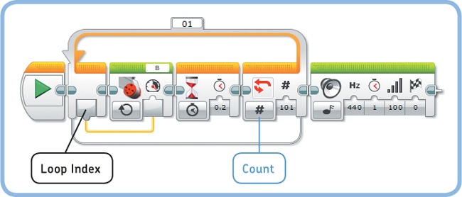
The Loop Index output plug (see Figure 14-22) gives you the number of times the Loop block has finished running the blocks inside it. The index begins at 0, incrementing by 1 each time the blocks in the loop run.
You’ll now make the Accelerate program, which uses the Loop Index as an input for the motor speed. When you start the program, the index is 0, which makes the motor run at 0 speed (it stands still) for 0.2 seconds. When the Loop block returns to the beginning, the Loop Index increases to 1, and it repeats the Motor block, this time setting the speed to 1. When it repeats, the motor speed is 2, and so on.
The Loop block is configured to run 101 times so that the speed is 100 when it runs for the last time. You’ll then hear a sound and the program ends. You could configure the loop to run, say, 150 times, but the motor will stop accelerating when the index exceeds 100 because 100 is the maximum speed.
You learned earlier that you can make the Loop block stop repeating after a certain number of repetitions, after a certain number of seconds, or when a sensor reaches a trigger value. In Logic mode, you can make a loop stop repeating using a Logic data wire.

The Loop block checks the data wire value each time it’s done running the blocks in the loop. If the data wire value is false, the blocks run again. If it’s true, the loop ends. In other words, the blocks repeat until the data wire value is true.
The LogicLoop program (see Figure 14-23) demonstrates this technique, using a Loop block in Logic mode and an Infrared Sensor block in Measure – Beacon mode. The Sensor block gives you the beacon heading and beacon proximity, but here you’ll use only the Detected output plug, which tells you whether the sensor successfully detects the beacon’s signal. If a signal is detected, the data wire carries out true, making the loop end; if no signal is detected, the data wire carries out false and the loop runs again. In other words, the program waits until the sensor picks up a signal, and then it plays a sound.
When you run the program, you should find that the sensor can successfully detect a signal up to around 3 meters (10 feet) away.
Discovery #80: IR Acceleration!
Can you make motor B accelerate until the Infrared Sensor successfully picks up a signal from the beacon?
Hint
Combine the Accelerate program (Figure 14-22) and the LogicLoop program (Figure 14-23) into a single program.

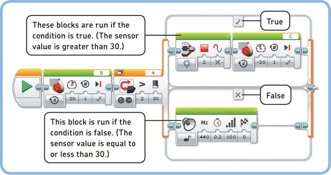
As you’ll recall from Chapter 6, you use Switch blocks to have your robot make decisions. The robot uses a sensor value to determine whether a given condition (such as “The proximity value is greater than 30%”) is true. If it’s true, the blocks at the top branch of the Switch block run (![]() ); if it’s false, the blocks at the bottom run (
); if it’s false, the blocks at the bottom run (![]() ), as demonstrated by the SwitchReminder program in Figure 14-24.
), as demonstrated by the SwitchReminder program in Figure 14-24.
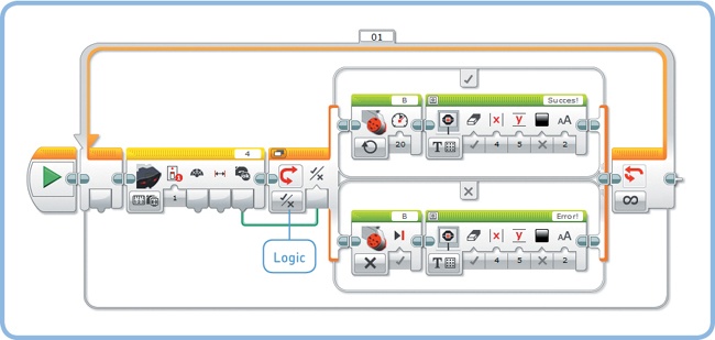
Rather than using a sensor value to make a decision, you can use a Logic data wire to control the Switch block by choosing Logic mode, as shown in Figure 14-25. If the data wire value is true, the blocks at the top of the switch run; if it’s false, the blocks at the bottom run.
The LogicSwitch1 program (see Figure 14-25) continuously checks whether the Infrared Sensor successfully detects the beacon. If so (true), the robot displays “Success!” on the EV3 screen and motor B moves; if not (false), it shows “Error!” and the motor stops. (The sensor stops receiving a signal about a second after you release the button, so it takes about a second for the error message to appear.)
If you set the Switch block to Numeric mode and you connect a Numeric data wire to it, you can choose specific actions to run for each value using the techniques you learned for Switch blocks with more than two cases, as discussed in Chapter 7 (see Figure 7-10). For example, you can make the robot say “Hello” if the data wire value is 3, “Good morning” if it’s 10, and “No” for all other values (the default case). You’ll try this out in the next chapter.
In some cases, it can be useful to connect data wires from outside a Switch block to blocks inside the switch. For example, you can modify your previous program to control the motor speed with the beacon proximity value without having to use another Infrared Sensor block.
To do so, toggle the Switch block to Tabbed View and connect the data wire as shown in Figure 14-26. The finished LogicSwitch2 program controls the motor’s speed with the beacon proximity if a signal is detected; it stops the motor otherwise.
As shown in Table 14-3, the beacon proximity value is undefined if no signal is detected. If the beacon proximity value is connected to a Motor block while no signal is detected, the Motor block receives no value, and it moves unpredictably. You can avoid this potential problem by making sure to use the value only when it contains a proper sensor measurement—that is, only if the Detected output is true.
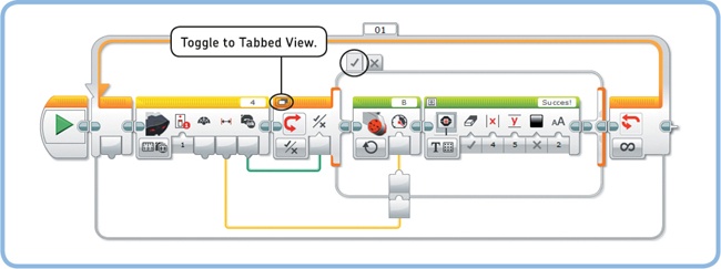
Figure 14-26. The LogicSwitch2 program. Start with the LogicSwitch1 program, switch to Tabbed View, bring forward the True tab, and connect the Numeric data wire as shown. (A pair of input and output plugs across the edge of the switch should appear automatically as you try to connect the wire.) The blocks on the False tab remain unchanged.
That’s why you need to use the Switch block in the LogicSwitch2 program. The sensor value is used to control the motor speed only when a signal is detected. Otherwise, the blocks on the False tab run and a Large Motor block in Off mode makes the motor stop.
In Beacon Heading mode, on the other hand, the output value will be 0 if either the beacon is directly in front of the sensor or no signal is received at all. You can distinguish between these two cases using the same technique as in our last program. For example, you could display the Beacon Heading value on the screen if the signal is detected and make the screen read “Error” otherwise.
The final way to make a Loop block stop repeating is to use the Loop Interrupt block. A Loop block normally checks a sensor condition or Logic value each time it finishes running the blocks inside it, but the Loop Interrupt block makes a specified loop end immediately.
You choose which loop you want to interrupt by selecting the Loop name from a list, as shown in Figure 14-27. You can use the Loop Interrupt block to end a loop from the inside or to end a loop that’s running on a parallel sequence. When a loop is interrupted, the program continues with the blocks that are placed after the loop.
The Loop Interrupt block can be useful to break out of a Loop block at any point in the loop, rather than having to wait for all of the blocks in the loop to finish. Consider the BreakFromInside program in Figure 14-27, which repeatedly turns motor B for one rotation and then says “LEGO.” If the Infrared Sensor’s proximity value is less than 50% after the robot says “LEGO,” the loop ends normally, and you’ll hear “MINDSTORMS” right after.
Thanks to the Loop Interrupt block, you can also end the loop by keeping the Touch Sensor pressed just after motor B turns. When you do, the program skips to the block after the loop, and you’ll hear only “MINDSTORMS.”
Create the program as shown in Figure 14-27, and run it a few times to determine which sensor should be triggered (and when) to make the loop end.
You can also interrupt a Loop block from a sequence running in parallel. When you do this, the loop ends and the program begins to run the blocks after the loop. At the same time, the program attempts to finish the block that was running when you ran the Loop Interrupt block.
For example, the BreakFromOutside program (see Figure 14-28) has a Loop block that repeatedly turns motor B for one rotation. On a parallel sequence, a Loop Interrupt block is run once the Infrared Sensor is triggered. The loop then ends, and the Sound block immediately plays a sound.
If you trigger the sensor when the motor is halfway through making its rotation, it will finish its rotation while the sound plays. So momentarily, the Large Motor block and the Sound block will run simultaneously.

Figure 14-27. The BreakFromInside program contains a loop called MyLoop, which ends if the Touch Sensor is pressed after the motor moves or if the Infrared Sensor is triggered after the robot says “LEGO.”

Figure 14-28. The BreakFromOutside program interrupts a loop called Move when the Infrared Sensor is triggered.
Now change the Duration setting of the Sound block to 0.1 seconds and run the program again. If you trigger the sensor when the motor is halfway through its rotation, the program ends almost immediately, stopping the motor before it completes its rotation.
I recommend that you use this technique with caution. Interrupting a loop that runs in parallel can make the robot behave unpredictably. (What happens, for instance, if you have motor B make another movement just after the loop? Will the previous block continue, or will the new block run?)
Note that interrupting the loop from the inside doesn’t introduce ambiguity as to what the program might do: The BreakFromInside program interrupts the loop, but it doesn’t interrupt another block that’s running.
Discovery #81: Interrupting Interrupts!
Can you create a program like the BreakFromInside program that continuously moves the motor and plays a sound until the Touch Sensor is pressed and the Color Sensor sees something green? Triggering these sensors simultaneously should end the loop after the motor moves. (You’ll learn about another way to make a loop end when multiple sensors are triggered in the next chapter, but for now, just use the Loop Interrupt block.)
Hint
Add a Switch block to the BreakFromInside program (see Figure 14-27).
In this chapter, you learned to use data wires to carry information from one block to another. In addition, you’ve learned to read sensor values with Sensor blocks and to work with the advanced features of Wait, Loop, and Switch blocks.
Most of the programs you’ve made so far with data wires are fairly small, and data wires may not seem very useful yet. However, data wires are essential to programming advanced robots like the ones you’ll build in Part VI. The following Discoveries will let you practice the programming skills you gained in this chapter.
Discovery #82: Sensor Practice!
Create a program that makes the white dial turn at a speed based on the Infrared Sensor’s proximity, but only while you press the Touch Sensor and touch the Color Sensor simultaneously. If either of these sensors isn’t triggered, the motor shouldn’t move.
Discovery #83: Power vs. Speed!
Create a program that makes motor B turn at 30% speed (51 rpm) using a Large Motor block, and motor C turn at 30% power using an Unregulated Motor block. Then, continuously display the speed of both motors using Motor Rotation blocks in Current Power mode. (Recall that this mode gives you the motor speed, as discussed in Chapter 9).
Now observe what happens as you try to slow down the motors with your hands. You should see the speed of motor C drop quickly: 30% power isn’t enough to overcome the friction applied by your hand. However, motor B keeps turning at almost 30% speed because the block makes the EV3 apply additional power to the motor when it is being slowed down.
Discovery #84: Real Direction!
Can you make a program that displays the Beacon Heading value if a beacon signal is detected, and can you make it display “Error!” if no signal is detected?
Hint
Use the LogicSwitch2 program (see Figure 14-26) as a starting point.
Discovery #85: SK3TCHBOT Is Watching You!
Create a program that counts the number of people walking by your robot. Place your robot in such a way that the Infrared Sensor can sense people in front of it. Place two Wait blocks inside a Loop block, and configure the first block to wait until the sensor sees someone passing by; use the second one to wait until the person is out of sight. Ultimately, the loop should go around once each time it senses someone going past. Now when you display the Loop Index on the EV3 screen, you’re displaying how many people have walked by. To ensure that your program works properly, place a Sound block inside the loop so that you’ll hear a sound each time someone passes by.
Design Discovery #25: Bionic Hand!
Can you design a robotic claw that you can attach to your arm? Use sensors and the EV3 buttons to control the movements of the claw. Add the Infrared Sensor and program the robot so that the arm will warn you when the sensor sees that you’re approaching a wall. Use the programming techniques you learned in this chapter to display sensor values on the screen or to make sounds based on sensor measurements.
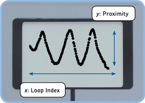
Discovery #86: Oscilloscope!
Can you turn your EV3 brick into a measurement device that records sensor measurements on the screen, as shown in Figure 14-29? Display proximity measurements as small circles whose x coordinate is determined by the Loop Index and whose y coordinate is determined by the proximity measurement. As the loop progresses, you should see new measurements appear one by one to form a plot like the one shown in the figure.
Because the screen has 178 pixels in the x direction, the Loop block should run 178 times to display 178 circles, with a 0.05-second pause between each measurement. Then, the program should erase the screen and start over.