Now that you know how data wires work, you can do some really interesting things with more of the programming blocks. For example, you can make the EV3 combine and process sensor values so that they can be used as input values for other actions. With the tricks you learn in this chapter, you’ll be able to program your robot to choose a random action or do something only when two sensors are triggered at the same time, rather than performing strictly preprogrammed actions.
You’ll learn in this chapter how to use the Math block to allow your robots to make calculations you can use in your programs. For example, the robot can calculate the distance it should travel based on a sensor reading. I’ll also introduce you to a few new programming blocks, such as the Random, Compare, and Logic blocks, and show you how to make My Blocks with inputs and outputs.
These techniques and programming blocks are essential to the advanced robot programs you’ll create in Part VI as well as for advanced programs that you’ll create for your own robots. As in Chapter 14, you’ll use SK3TCHBOT to test the new programs in this chapter.
The Discoveries in this chapter might be a bit challenging at first, but they will help you master essential programming skills, which will let you create much more interesting programs and build some really smart robots!
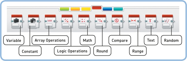
The Programming Palette contains a series of blocks that you have not used yet: Data Operations blocks (see Figure 15-1). Data Operations blocks include the Math block, the Random block, the Compare block, and the Logic Operations block. Each block has its own function, but they all process values carried by data wires and generate new values based on the input values. This section will explain how to use these blocks in your programs.
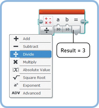
The Math block (see Figure 15-2) allows the EV3 to do arithmetic operations, such as addition, subtraction, multiplication, and division. You enter two numbers in the a and b fields on the block, and you use the Mode Selector to choose which operation, such as division, should be applied to them (in the case of division, a will be divided by b). A data wire outputs the result. Instead of entering numbers for a and b yourself, you can supply them with a data wire.
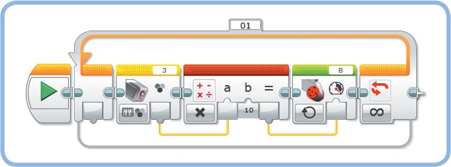
The program in Figure 15-3 shows the Math block performing multiplication on the Color Sensor’s measurement to control the speed of motor B. The Color Sensor value (a number between 0 and 7) isn’t suitable to control the speed because it would make the motor turn very slowly (7% speed at best). The Math block multiplies the sensor value by a factor of 10 and sends the result (a number between 0 and 70) to the Motor block’s Power setting. As a result, the motor moves at 10% speed for black, 20% speed for blue, and so on, up to 70% speed for brown.
Create a new project called SK3TCHBOT-Data with a program called MathSpeed, as shown in Figure 15-3.
Discovery #87: 100% Math!
The Math block in the MathSpeed program makes it possible to use the detected color to control the motor’s speed, but the speed only goes up to 70%. Can you modify the program to use the full range of the motor speed values? Add a Display block to your program to verify that the Math block’s output reaches 100% when brown is detected.
Some calculations require more than one arithmetic operation. For example, you might want to subtract two numbers and multiply the result by a third number. You could use two Math blocks to do this (one for subtraction and one for multiplication), but you can perform both calculations using just one Math block in Advanced mode, as shown in Figure 15-4.
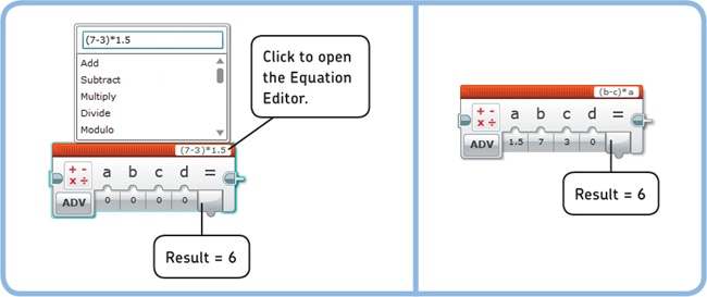
In the Equation setting, you enter the calculation that the Math block should do just as you would enter it on a pocket calculator. For example, entering (7-3)*1.5 will result in an output of 6. (Just as on a calculator, you use parentheses to ensure that the subtraction is done before the multiplication.)
You can also use symbols in the equation (a, b, c, or d) and type a value for each symbol in the a, b, c, and d settings. For example, entering (b-c)*a as the equation and entering 7 for b, 3 for c, and 1.5 for a gives the same output result: 6. Finally, you can supply values for each symbol using a Numeric data wire.
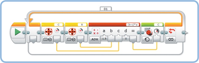
To see the Advanced mode in action, you’ll create a program that makes motor C (red dial) follow the movements of motor B (white dial), which you turn manually. Because motor C is mounted upside down in your robot, the dial will actually turn in the opposite direction, but it will turn by the same amount. To accomplish this, you’ll set the speed of motor C as follows:
Speed of motor C = (Degr. of motor B − Degr. of motor C) × 1.5
To see why this formula works, consider what happens when you turn motor B forward by 70 degrees while motor C is at 60 degrees. The speed of motor C will be set to (70 − 60) × 1.5 = 15, making motor C turn forward to catch up with B. If C is ahead of B, the result is negative and motor C turns backward. The greater the difference between the motor positions, the faster motor C moves. Once both motors are in the same position, the result is 0, making the motor stop.
Create the PositionControl program shown in Figure 15-5. Turn the white dial manually, and watch the red dial follow the same movement in the opposite direction.
Because the Math block is an essential component of many programs that use data wires, it’s a good idea to practice with it before you continue. These Discoveries will get you started.
Discovery #88: Added Value!
Can you create a program that continuously displays both an Infrared Sensor’s proximity measurement and a Color Sensor’s reflected light intensity measurement on the screen as well as the sum of the two?
Discovery #89: Infrared Speed!
Create a program similar to the MathSpeed program to control the speed and direction of motor B using the Infrared Sensor’s proximity measurement. The motor should turn at 50% speed for 100% proximity, stand still for 50% proximity, and rotate at −50% speed (reverse) for 0% proximity.
Discovery #90: Double Infrared Speed!
Can you expand the program from Discovery #89 to make the motor speed range between −100 and 100?
Discovery #91: Gain Control!
What is the effect of the 1.5 value in the PositionControl program? Experiment by changing the value to a low number (0.1) or a high number (5) and observing how fast motor C can follow your movements.
The Random block allows you to generate a random value to use in your program. In Logic mode, the output is a Logic data wire carrying either true or false. Using the block in this mode is like tossing a coin, with the result being either true (heads) or false (tails). For a coin flip, the probability of getting true is 50%, resulting in true about half of the time. The Random block enables you to specify the likelihood of getting true using the Probability of True (%) setting. For example, entering 33 should result in true roughly one-third of the time, while the output would be false two-thirds of the time.
In Numeric mode, the output is a Numeric data wire carrying a random integer number in the range specified by the Lower Bound and Upper Bound settings. For example, setting 1 as the lower bound and 6 as the upper bound should result in 1, 6, or any whole number in between, with each number equally likely to occur, as when rolling a die.
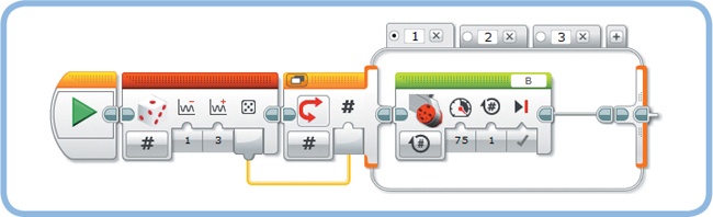
The Random block is useful when you want your robot to do something unexpected. For example, you could use a Random block to randomly say “Left” or “Right” or to make the white dial turn at a random motor speed, as shown in the RandomMotor program in Figure 15-6.
The Switch block in the RandomMotor program runs either the block at the top (true) or the blocks at the bottom (false). You can have the program randomly choose between more than two cases by setting the Random block and the Switch block to Numeric mode. This allows you to specify actions for each possible random value, as demonstrated by the RandomCase program in Figure 15-7.
Discovery #93: Random Frequency!
Can you make the EV3 play a random tone for half a second each time you press the Touch Sensor? Generate a random value and wire it into the Frequency plug of a Sound block. Finally, expand the program to also display the frequency on the EV3 screen.

The Compare block checks to see whether a Numeric value is Equal To (=), Not Equal To (≠), Greater Than (>), Greater Than Or Equal To (≥), Less Than (<), or Less Than or Equal To (≤) another Numeric value. You can enter the values you’d like to compare in the block’s settings (a and b), or you can supply the values to the block with data wires.
The Compare block outputs one Logic data wire (true or false) based on the result of comparing value a to value b. For instance, if you set the mode to Equal To (=), the block outputs true if value a is equal to b.
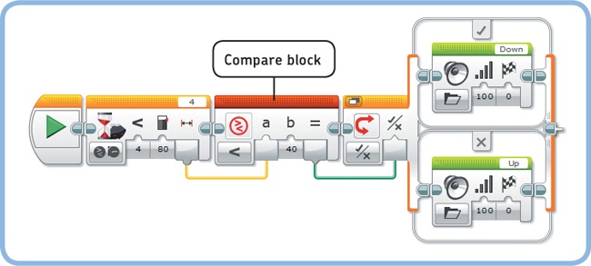
The CompareValues program in Figure 15-8 shows the Compare block in action. In this program, the robot waits until the proximity measurement drops below 80. The measurement that made the Wait block stop waiting is transferred to the Compare block, which determines whether it is less than 40. If so (true), SK3TCHBOT says “Down”; if not (false), it says “Up.”
As a result, the robot says “Down” if you quickly place your hand in front of the sensor, approaching it from the side, but it says “Up” if you slowly approach from the front.
Discovery #94: Random Motor and Speed!
Create a program that generates a random number between 10 and 100 to control the speed of either motor B or motor C. If the random value is less than 50, motor B should turn for one rotation with its Power setting controlled by the random value; if not, motor C should turn for one rotation at the random speed.
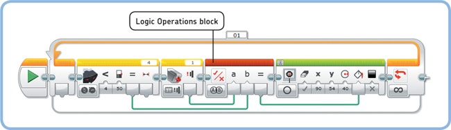
The Logic Operations block compares two Logic data wire values and outputs the result with a Logic data wire. In And mode, it checks to see whether both input values (a and b) are true. If so, the Result output is true. If one or both inputs are false, the output is false.
You can use the Logic Operations block in this mode to create a program that draws a filled circle on the screen if both the Touch Sensor is pressed and the proximity measurement is less than 50%. If either or both conditions don’t occur, the display shows an empty circle because the Logic Operations block’s output is false. Figure 15-9 shows the LogicAnd program.
When configuring the Logic Operations block, you can select one of four modes: And, Or, XOR, and Not. Each option will make the block compare the logic input values differently. The option you choose will depend on what you want your program to do. Table 15-1 lists the available modes as well as the input values that make the output value true.
In Or mode, the block’s output is true if either or both input values are true, as demonstrated by the LogicOr program shown in Figure 15-10. The program repeatedly checks whether the Touch Sensor or the Infrared Sensor is triggered. If one or both are triggered, the Result output is true, causing the loop to end. Once the loop ends, the Sound block plays a tone. This technique is useful because it allows you to make your program wait until at least one of several sensors is triggered.
Now change the mode of the Logic Operations block to XOR. When you run the program, you should hear the sound when either the Touch Sensor or the Infrared Sensor is triggered, but the sound won’t play if both sensors are triggered at the same time.

Discovery #95: Logic Sensors!
The LogicOr program plays a sound when the Touch Sensor or the Infrared Sensor is triggered, but it doesn’t tell you which sensor caused the loop to end. Can you expand the program to say “Touch” if the Touch Sensor ended the loop and “Detected” if the Infrared Sensor was involved?
When you select Not mode, the Logic Operations block has only one input. This mode just inverts the input signal: If the input value (a) is true, the output will be false; if the input value is false, the output will be true.
To see this mode in action, modify the LogicOr program you just made by removing the Infrared Sensor block, and change the mode of the Logic Operations block to Not. The output of the Logic Operations block will be false if the Touch Sensor is pressed and true if it’s released so that the loop runs until you release the sensor.
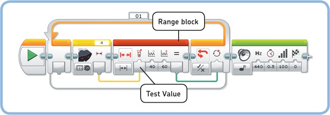
The Range block determines whether a Numeric data wire carries a value within a range specified by a Lower Bound and Upper Bound. The boundary values themselves are considered to be inside the range.
When you select Inside mode, the block’s Result output is true if the Test Value is in the range; the output is false if it’s outside the range. When you select Outside mode, the opposite occurs: The Result output is true if the Test Value is outside the specified range; the output is false if it’s inside the range.
The SensorRange program (see Figure 15-11) uses a Range block (Inside mode) and a Loop block (Logic mode) to wait for the Infrared Sensor’s proximity value to attain a value of 40, 60, or somewhere in between.
The Round block can turn a decimal input value into an integer by rounding it. You can select a mode to Round Up (1.2 or 1.8 becomes 2), Round Down (1.2 or 1.8 becomes 1), or round to the Nearest value (1.2 becomes 1, while 1.5 or 1.8 becomes 2). You can also choose Truncate mode to remove decimals from the number without rounding (1.877 becomes 1.8 if you choose to keep only one decimal).
The RoundTime program (see Figure 15-12) displays the time elapsed since the start of the program on the EV3 screen by rounding the decimal timer value (such as 3.508) down to a whole number of seconds (3).
We haven’t used the Timer block in a program before, but its use is straightforward. The block measures time much like a stopwatch, starting at 0 when the program begins. A Timer block in Measure mode gives the current time as a decimal value, such as 1.500 for one and a half seconds. You can reset the timer to 0 by using the block in Reset mode.
You can use up to eight different timers in your program. For example, you can use timer 1 to measure how long the program has been running and timer 2 to measure how much time has passed since you pressed the Touch Sensor by resetting it each time you press the sensor. To specify which timer value you want to read or reset, you choose from one of eight Timer IDs. You used Timer ID 1 in the RoundTime program.
The Text block combines up to three Text data wire inputs into a single text line. For example, if the input text lines are “EV3”, “is”, and “fun”, the Result output value will be “EV3 is fun”. You have to add a space after both “EV3” and “is”, or the output will simply be “EV3isfun”. If an input is empty, it will be ignored.
You can use the Text block to combine text and a number for display on the EV3 screen. For example, you can expand the previous program to say “Time: 41 s” rather than just displaying a number. To do so, you merge the word “Time:”, the numeric time value, and “s” and display the result on screen, as shown in the TextTime program in Figure 15-13.
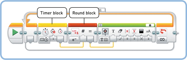
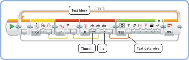
Figure 15-13. The TextTime program. Don’t forget the spaces in “Time:” and “s” (indicated here with blue boxes). After 41 seconds, the display should say “Time: 41 s”.
Up to now, you’ve seen how to use data wires to send information between existing programming blocks, like Sensor blocks, Data Operations blocks, and Action blocks. You can also use data wires with your custom-made My Blocks. Doing so makes it possible to create My Blocks with parameters (inputs and outputs). For example, you can create a My Block to display the value passed to it by a data wire.
You learned how to create basic My Blocks without inputs or outputs in Chapter 5. In this section, you’ll learn to create My Blocks with input and output plugs. You’ll also learn about some strategies for creating useful My Blocks.
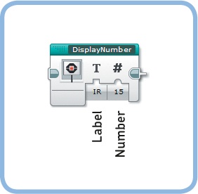
To get started, you’ll create a My Block with two input plugs called DisplayNumber, as shown in Figure 15-14. The purpose of this block is to combine the information from the Text input called Label and the Numeric input called Number and display the result on the EV3 screen.
This block will make it easy to display a number on the screen with a label to describe it. For example, entering IR as the Label and 15 as the Number will make the block display IR: 15.
Create the My Block by following these steps:
Create a new program called NumberTest. You’ll need it to test the My Block when it’s ready.
Place and configure a Text block and a Display block on the canvas, as shown in Figure 15-15. You’ll use the Text block to combine the Label input, a colon followed by a space, and the Number input into one text line, and you’ll use a Display block to show it on screen. Then, select both blocks by dragging a selection around them with your mouse.
Open the My Block Builder by going to Tools > My Block Builder.
Enter DisplayNumber as the My Block’s name, enter a description, and choose an icon for your block, as shown in Figure 15-16.
Now, we’ll configure the block’s parameters. Add two inputs by clicking Add Parameter twice, as shown in Figure 15-17.
Open the Parameter Setup tab, select the first parameter, and configure it as a Text input called Label, as shown in Figure 15-18. Also, choose a descriptive icon, such as the T icon, for this input on the Parameter Icons tab.
Now, select the second parameter, and configure it as a Numeric input called Number, as shown in Figure 15-19. The Default Value is set to 0, which means that the Number setting will be 0 by default when you pick it from the Programming Palette later. Choose the standard input plug in the Parameter Style option. This creates a basic Numeric input plug that accepts any value (like the inputs on a Math block), rather than one with a slider that accepts only a range of values (like the Power and Steering settings on the Move Steering block).
Click Finish. You should now see the contents of the DisplayNumber My Block on its own tab inside your project, as shown in Figure 15-20. You should also see the Label and Number plugs, although the wires aren’t connected yet. The plugs carry the values passed to the My Block from the main program. That is, if you enter IR and 15, as shown in Figure 15-14, Label carries IR and Number carries 15.
Complete the My Block by connecting the Label and Number values to the Text block, as shown in Figure 15-20, and save your project. (Recall that the Text block combines the information from its inputs into one text line. The Display block shows it on the screen.)

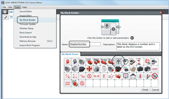
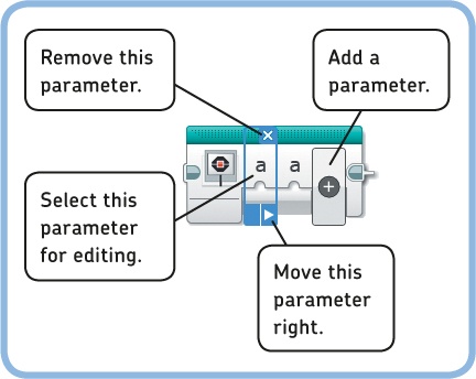
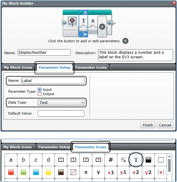

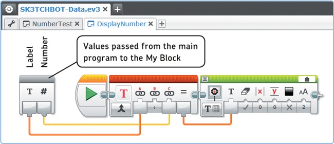
Figure 15-20. Once you click Finish in the My Block Builder, you’ll see the DisplayNumber My Block on its own tab in the SK3TCHBOT-Data project. Finish the block by connecting the wires as shown.
Congratulations, you’ve created a My Block with inputs! You’ll find the My Block on the light blue tab of the Programming Palette. Now, finish the NumberTest program to test your newly created block, as shown in Figure 15-21. In this example, the main program (NumberTest) passes two values to the My Block (DisplayNumber). The blocks inside the My Block retrieve these values and display them on the EV3 screen.
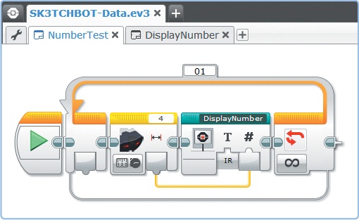
Figure 15-21. The NumberTest program. The Infrared Sensor block sends the proximity measurement to the Number input plug of the DisplayNumber My Block, while you enter a value for the Label manually (IR). The My Block combines the Label with a colon, a space, and the sensor value, and it displays the result on the EV3 screen. For a measurement of 65, for example, the screen will show IR: 65.
Once you’ve created a My Block, you can alter its functionality by double-clicking the block and changing the blocks within it. For example, you can add a Sound block to the DisplayNumber block to have the robot beep each time it displays a number.
As of this writing, the LEGO MINDSTORMS EV3 software (version 1.10) doesn’t allow you to edit the input and output parameters of a My Block after you create it with the My Block Builder. If you need to modify parameters or add new ones, you’ll have to create a new My Block from scratch. (Once you’ve created the new block with its parameters, copy the contents of the old block and paste them into the newly created one to save time.)
Discovery #98: My Unit!
Create a new My Block based on the DisplayNumber My Block with an additional Text input called Unit (see Figure 15-22). Then append the unit of measurement to the number. For example, displaying the Rotation Sensor value by entering MB as the label and Deg as the unit should result in MB: 375 Deg (short for Motor B: 375 Degrees).

Discovery #99: Enhanced Display!
The DisplayNumber My Block you just made is useful only for displaying a single value at the top of the screen. Can you create a more useful version of this My Block with a setting to choose a line number and a setting to clear the screen, as shown in Figure 15-23?

Besides making My Blocks with inputs, you can also create your own blocks with output plugs. To see how this works, you’ll create a My Block that detects the direction of moving objects with the Infrared Sensor. The Direction My Block has one Logic output plug called Approaching, as shown in Figure 15-24.
The output is true if an object is approaching the sensor (the distance to an object is decreasing); the output is false otherwise (either the distance to the object is increasing or unchanging). Create the Direction My Block and the DirectionSound test program using the steps that follow.
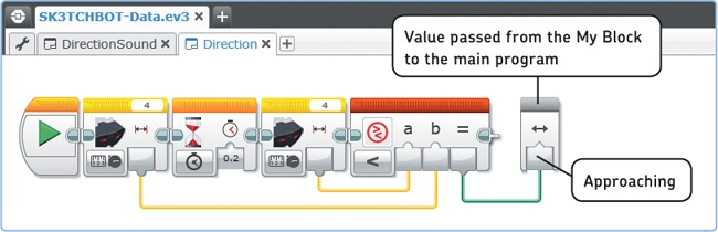
Create a new program called DirectionSound, and place two Infrared Sensor blocks, a Wait block, and a Compare block on the Canvas, as shown in Figure 15-25. These blocks take two proximity measurements 0.2 seconds apart and compare them to see whether the second value (a) is less than the first (b). If so, then the object is approaching the sensor, and the Compare block’s output will be true.
Select each of the four blocks and go to Tools > My Block Builder. Enter Direction as the block’s name, and choose the Infrared Sensor as its icon, as shown in Figure 15-26.
Add one parameter, configure it as a Logic output called Approaching, and select an appropriate symbol, as shown in Figure 15-26. Then, click Finish.
To complete the My Block, connect the Result output of the Compare block to the Approaching plug, as shown in Figure 15-27. This value is then passed to the main program, which contains the Direction My Block.
Now, return to the DirectionSound program, and test your My Block by having the robot play a high-pitched tone when an object is approaching (true) and a low tone when the object is moving away or standing still (false), as shown in Figure 15-28. In this example, the blocks inside the Direction My Block calculate the direction of the moving object and pass the result to the main program (DirectionSound) through the Approaching plug.
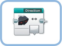

Figure 15-25. Configure the blocks for the Direction My Block as shown. When you’re ready, drag a selection around the blocks and launch the My Block Builder.

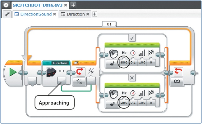
Figure 15-27. The DirectionSound program uses the Logic value from the Approaching output to play a high-pitched sound if an object is approaching and a low tone if it’s not approaching.
Discovery #100: Proximity Average!
Create a My Block that calculates the average of two proximity measurements. Then make it output the result with a Numeric data wire. As in the Direction My Block, the measurements should be taken 0.2 seconds apart.
Discovery #101: Proximity Rate!
Create a My Block with one Numeric output that determines the speed of a moving object by calculating the rate at which the proximity value changes. To accomplish this, have the block take two sensor measurements, as in the Direction My Block, and calculate the rate of change as follows:

To test the block, display the speed value on the screen, and change the brick status light to green if an object is approaching, orange if the object is standing still, and red if the object is moving away from the sensor. How can you determine the direction using the speed value?
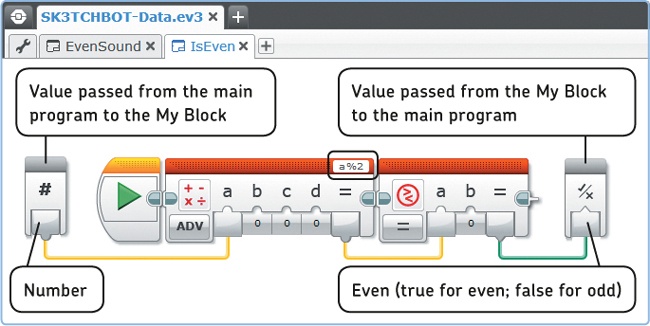
In the final example, you’ll create a My Block with both an input and an output plug, as shown in Figure 15-29. The IsEven My Block determines whether a Numeric input value called Number is even. If it is, a Logic output called Even carries out true; if it’s not, it carries out false. Create the block using the following steps:
Create a new program called EvenSound, and place a Math block and a Compare block on the Programming Canvas. (For now, just leave their settings unchanged.)
Select the two blocks you’ve just placed, and open the My Block Builder. Enter IsEven as the block’s name, and choose the icon shown in Figure 15-29.
Add one Numeric input plug called Number and one Logic output plug called Even, and configure the icons as shown in Figure 15-29. Click Finish.
Now, complete the My Block by configuring the two blocks and connecting the data wires as shown in Figure 15-30. The Math block uses the modulo operator (%), which calculates the remainder after dividing two numbers. In this case, it tells us the remainder of dividing the input value a by 2. Even numbers are divisible by 2, so the remainder will be 0 and the Compare block will carry out true. For odd numbers, the remainder isn’t 0, causing the Compare block to output false. (For example, 7%2 gives a remainder of 1, and the Compare block outputs false, which tells us the input is an odd number.)
Now that you’ve finished creating the My Block, test it by completing the EvenSound program, as shown in Figure 15-31. The program displays a random number between −100 and 100 on the EV3 screen, and it determines whether the number is even or odd using the IsEven My Block. The robot says “Yes” for even numbers and “No” for odd numbers.


Creating My Blocks with inputs and outputs allows you to create a wide variety of blocks. My Blocks can be useful for the following:
Repetitive tasks: There are some things you’ll do in many of your programs, such as displaying values on the screen. If you create a My Block for such a task once, you’ll save time in the long run.
Program organization: You can break down large programs into My Blocks to make it easier to understand your program and to test parts of it individually. For example, if you were to create a program for an autonomous robotic arm, you could create one My Block to localize an object, another to drive toward it, and a third to lift and move the object.
Processing information: As you create programs that process values with Data Operations blocks, it can be difficult to understand how your program really works when you look at it later. To resolve this, you can break down complex calculations into smaller ones, grouped into My Blocks. For example, in the EvenSound program (see Figure 15-31), hiding the modulo operation in the IsEven My Block makes it easier to see how the program works.
You can begin creating a My Block in two ways:
Convert a selection of blocks into a My Block: Use this method if you have already configured and tested the blocks in your program. This is a useful technique to break a large program into subsections, each with its own functionality. If your selection of blocks is connected to other blocks in your program with data wires, you should configure a My Block parameter for each data wire. In fact, the My Block Builder automatically configures such parameters, but you’ll still need to add a descriptive name and icon for each one.
Create a My Block from scratch: Use this method if you know what your My Block should do but are not yet sure how to configure the blocks inside it to accomplish the task. For example, if you want to create a block that determines whether a number is even or odd but don’t know how it will work exactly, you could start by making a My Block with one Numeric input and one Logic output. Once it’s created, experiment with blocks inside the My Block until you accomplish the required task. (Note that you can’t start the My Block Builder without selecting any blocks, so you’ll have to start from a dummy block, like a Wait block, and delete the dummy block later.)
When you create a My Block, it will be accessible for use only within your current project. To use it within another project, you’ll have to copy or export it from your current project and paste or import it into the other. (See managing my blocks in projects.)
In this chapter, you learned about Data Operations blocks as well as how to create My Blocks with input and output parameters. These techniques will allow your robot to process and combine sensor values in order to use them as inputs for actions such as sounds and movements. You’ll see many practical examples of this in the remaining chapters of this book. For now, practice your newly acquired skills with the following Discoveries.
Discovery #103: Is It an Integer?
Can you create a My Block that determines whether a Numeric input value is an integer (a whole number) rather than a decimal? Create a My Block called IsInteger with parameters similar to those of the IsEven My Block, but use different blocks on the inside.
Discovery #104: Double Stalled!
Can you create a program that has both motor B and motor C turn until either one of them is stalled? When you’re ready, turn the blocks that make the program wait until a motor is stalled into a My Block called WaitForStall so you can use it in any of your programs. (It would be especially useful for vehicles like EXPLOR3R and the Formula EV3 Racer).
Hint
Part of your program is similar to the LogicOr program in Figure 15-10. Use two Motor Rotation blocks in Compare – Current Power mode.
Note
Remember that you can find the solutions to many of the Discoveries on the book’s companion website (http://ev3.robotsquare.com/).
Discovery #105: Reflex Test!
Can you create a program to test your reaction time? Make the brick status light turn green for a random amount of time and then turn red. As soon as you see the red light, you should press the Touch Sensor. The program should then display the time it took for you to see the red light and press the sensor. Place the whole program in a loop to see whether you can improve your reaction time! When you’re ready, expand the program to prevent people from cheating by pressing the Touch Sensor early.
Design Discovery #26: Robot Clock!
Can you build your own working EV3 clock? Use the three motors in the EV3 set to control the hour, minute, and second hands on your clock. Use the timer block and calculate the position of each hand based on the number of seconds elapsed since the start of the program.