
8
shot-roller: a robotic defense system
Now that you’ve learned how to control motors, use sensors, and program the NXT, you can begin making more complex machines. This chapter will show you how to build and program the Shot-Roller (Figure 8-1). This three-wheeled construction can shoot balls in any direction.
NOTE Enjoy the Shot-Roller, but remember to never shoot at people! As long as you respect the safety of others, this is not a dangerous robot.
The Shot-Roller can operate in either autonomous or remote-control mode. In autonomous mode, it does everything by itself. You can program it to look around and shoot at targets detected by the Ultrasonic Sensor or to respond to light signals using the Color Sensor. In remote-control mode, you use two Touch sensors to completely control the robot’s actions. The sensors are used as buttons to activate the shooter’s movements.
Unlike the Explorer and the Discovery robots that you built earlier in this book, the Shot-Roller uses three motors, as you can see in Figure 8-1. The Turn motor enables the robot to spin around in order to look for targets; the Turret motor moves the turret up and down; and the Firing motor is the shooter, which can shoot balls at high speed. The combination of these three motors allows the robot to fire in any direction!

In addition to building the Shot-Roller, you’ll learn some new programming techniques. You’ll also get to use some new programming blocks such as the Color Lamp block and the Motor block.
building the shot-roller
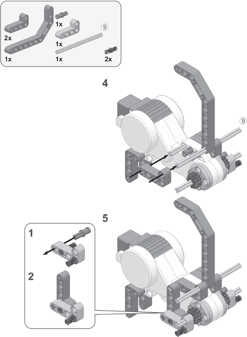
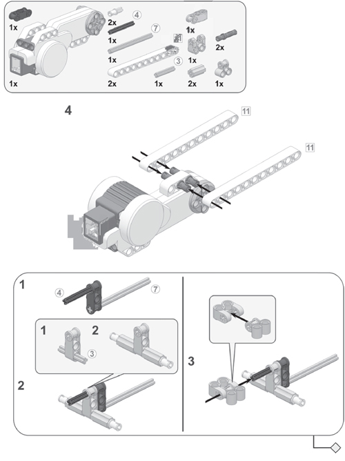
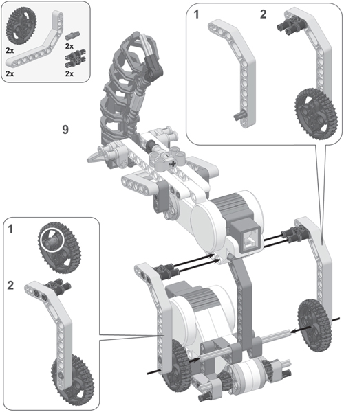
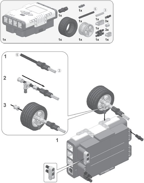
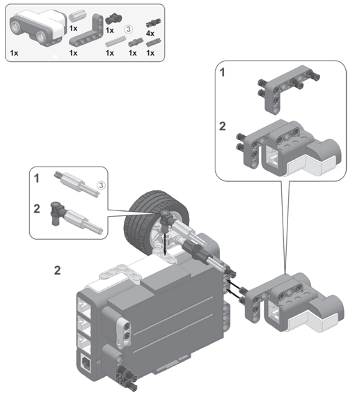
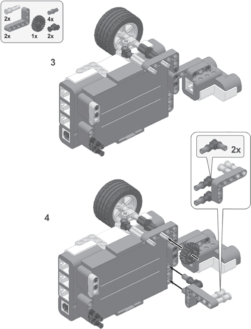
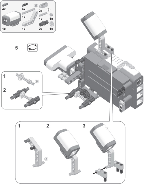
Now that you’ve learned a bit about Shot-Roller’s functionality, you’re ready to build it. To do so, follow the directions on the next pages, but first select the pieces you need as shown in Figure 8-2.

Figure 8-2: The required pieces to build the Shot-Roller


connecting the cables
Connect the sensors and motors to the NXT brick according to Table 8-1, making sure that they do not interfere with the wheels. One way to accomplish that is to wind the cables around several LEGO pieces on the robot.
Make sure that your robot can turn around smoothly and move the turret up and down easily, without having the cables blocking these movements. Check this by moving the turret and the wheels with your hands.
table 8-1: cable placement for the shot-roller
From motor/sensor |
To NXT brick port |
Cable length |
Turret motor |
Output port A |
Medium (35 cm/15 inches) |
Turn motor |
Output port B |
Medium |
Firing motor |
Output port C |
Medium |
Color Sensor |
Input port 3 |
Medium |
Ultrasonic Sensor |
Input port 4 |
Short (20 cm/8 inches) |
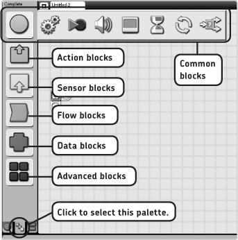
Figure 8-3: The Complete Palette. To open this palette, select the appropriate tab at the bottom of it. Hover your mouse pointer over the colored icons to see the programming blocks in each category.
programming the shot-roller
Before you program your robot, let’s look at some new programming blocks that you’ll need for your programs.
the complete palette
The NXT software has three different Programming Palettes. So far, you’ve used only the Common Palette (for most blocks so far) and the Custom Palette (for the My Blocks). Now you’ll use the Complete Palette, as shown in Figure 8-3. This palette contains all blocks that can be used in an NXT program, except for the My Blocks that you create yourself.
Each colored icon on the Complete Palette represents a certain type of block in the categories Common, Action, Sensor, Flow, Data, and Advanced blocks.
* Common blocks are the blocks from the Common Palette. The Common blocks are just a collection of frequently used blocks. Since blocks such as the Display block and the Sound block are Action blocks, you’ll also find them among this category; there is no difference between the Sound block in the Common category and the Sound block in the Action category.
* Action blocks are blocks to make the robot perform an action, such as turning motors, playing a sound, or displaying a line of text on the NXT screen.
* Sensor blocks (colored yellow) are blocks to read values from sensors for use in your programs. These blocks differ from the blocks that you’ve used so far to poll sensors, such as the orange Wait block. (I’ll show you how to use the yellow Sensor blocks in Chapter 10.)
* Flow blocks (like the Wait block) are typically used to change a program’s flow. For instance, some blocks may need to be repeated (with a Loop block), or a decision may need to be made (with a Switch block).
I’ll discuss some of the Data and Advanced blocks later in this book.
the color lamp block
In Chapter 7 you learned that you can use the Color Sensor to determine the color of a surface, but you can also use it as a red, green, or blue lamp. To use it as a lamp, you use the Color Lamp block in the Action blocks.
To use the Color Lamp block, open the Configuration Panel, select the port it’s connected to, then choose whether to turn the lamp on or off (in the Action box), and finally set the color of the lamp.
Let’s create a program that turns the sensor into a disco lamp that quickly flashes different colors. Start a new program called TestColorLamp, and place and configure four blocks in it as shown in Figure 8-4.

Figure 8-4: The configuration of the blocks in the TestColorLamp program
When you run TestColorLamp, you should see colored flashes coming from the sensor. You see this effect because you don’t use a Wait block to tell the program to pause. Immediately after the first Color Lamp block instructs the sensor to display a red light, the second block requests a blue light and then a green light. This sequence is repeated over and over with the Loop block.
the motor block
Like the Move block, the Motor block in the Action blocks controls a motor. The important difference between the two is that the Motor block has extra features for controlling individual motors, while the Move block is perfect for vehicles with two wheels like the Discovery we used in earlier chapters. Because the Shot-Roller uses three motors, each for a different function in the robot, you’ll use Motor blocks to control them individually.
Some of the configurations in a Motor block are the same as those in a Move block. For instance, you can use the Motor block’s Configuration Panel to select to which output port the motor is connected, in which direction the motor should turn, the motor power, and the time of rotation (Duration); you can also tell the robot what to do when the motor finishes rotating (Next Action).
using the control motor power option
One unique setting in the Motor block is the Control Motor Power option. Normally, when you set a motor to move at a certain power level (such as 50), the motor turns more slowly when you try to stop it with your hands because the power to the motor stays constant. However, when you use the Control Motor Power option, the NXT will automatically apply more power to the motor when there’s a load on it so that the motor continues turning at a constant speed. You can see a Motor block with its Configuration Panel in the following sample program.
To illustrate the Control Motor Power setting, you’ll shoot two balls with the Shot-Roller’s Firing Motor. To shoot a ball, the motor has to make one full rotation. You’ll launch the first ball with a Motor block specified to control the motor power and with the second one without the power control, as shown in Figure 8-5.
When you run the program, the first ball should be released at high speed because the motor power is controlled, while the second ball is stuck in the ball magazine: there is not enough power to push it out.

Figure 8-5: The configuration of the blocks in the MotorControlTest program
autonomous mode
Now that you know how to use the Motor and Color Lamp blocks, you can start making better programs for the Shot-Roller! You’ll begin by creating some programs that make the robot do everything by itself, without your help. In this autonomous mode, the NXT controls the motors and the robot’s actions based on the running program and input from the sensors.
In your next program, you’ll use the Color Sensor as a Color Lamp, so in effect, the only real sensor you’ll use is the Ultrasonic Sensor. Your program will instruct the Shot-Roller to turn around while looking for targets. If the robot sees a target, it will raise the turret. If the target is closer than 25 cm (10 inches), it will fire two balls; otherwise, it will fire just one. Once the balls have been fired, the robot lowers its turret, and the robot returns to the beginning of the program, looking for targets again. The Color Lamp indicates the state of the shooter: scanning for targets (blue light), aiming with the turret (green light), and firing (red light).
NOTE Before starting the program, make sure that the shooter is parallel to the ground.
creating the program
Create a new program called Shot-Roller-Autonomous, and then follow the instructions in Figures 8-6 through 8-10.

Figure 8-6: Step 1: You make the Turn motor move by activating motor B with the Duration option set to Unlimited. As the Shot-Roller turns right, a Wait block makes the Ultrasonic Sensor look for targets in sight. Once the robot sees a target closer than 45 cm (18 inches), motor B is turned off, and the turret is raised by spinning motor A backward.
NOTE In addition to the newly placed programming blocks, Figure 8-7 also shows some of the blocks placed previously. You don’t need to configure these blocks again; they just help you see where to put the new block. You may also see such blocks from previous steps in other figures in this book.
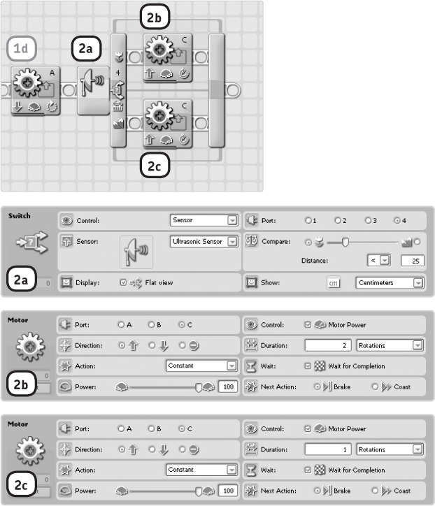
Figure 8-7: Step 2: The Wait block in step 1 waited until the sensor saw something closer than 45 cm, but it couldn’t determine exactly how close a target was. To find out, you use a Switch block. If the detected object is closer than 25 cm (10 inches), you shoot two balls, and just one otherwise.
NOTE When you pick a Wait block from the Programming Palette (among the Flow blocks), it is by default configured to poll the Touch Sensor. To make it wait for a certain number of seconds, set the Control box to Time (Figure 8-8).
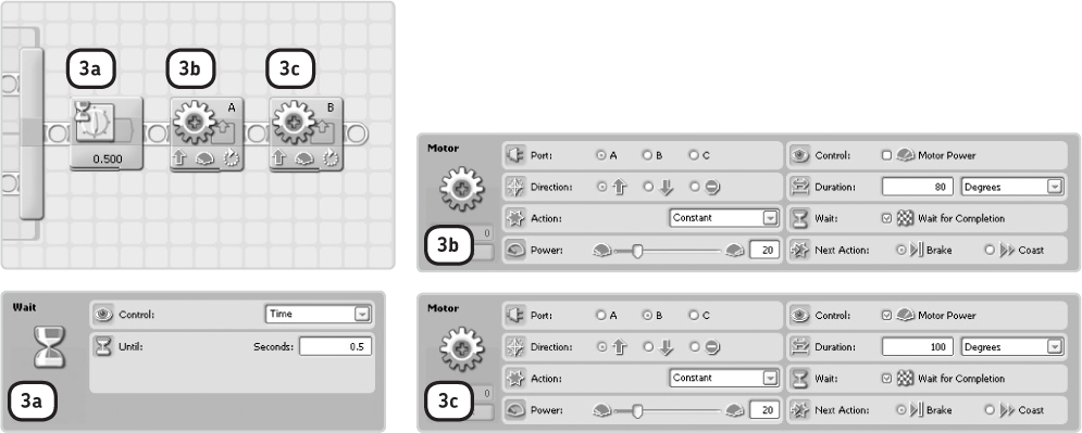
Figure 8-8: Step 3: After the robot shoots the balls, it waits for half a second, lowers the turret, turns slightly, and then starts the whole program over again—all to keep it from shooting at the same target repeatedly.

Figure 8-9: Step 4: You use a Loop block to repeat the sequence of blocks by placing a Loop block at the start of your program (before block 1a) and then selecting the rest of the blocks and dragging them into the Loop block. The result is the program shown in this figure.
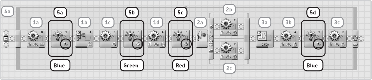
Figure 8-10: Step 5: Finally, you insert the Color Lamp blocks to indicate the state of the shooter as shown, and you configure the Color setting in each block’s Configuration Panel as indicated. This figure shows the final program.
Congratulations! You’ve finished creating the program. Now you can download it to the Shot-Roller and run it!
light sensor mode
In addition to using the Color Sensor as a color detector and a colored lamp, you can use it to measure the light intensity in a particular area. For example, it can measure the difference between bright areas covered in sunlight and a dark closet. The sensor values range from 0 to 100. A sensor value of 0 says that the sensor sees no light, while a value of 100 indicates that it sees very bright light. You can see the settings of a Wait block configured to poll the Color Sensor in Light Sensor mode in Figure 8-11.
Use the Until box to specify which value the sensor should measure in order for the Wait block to stop waiting. The block that you see here waits until the sensor reports a light value brighter (greater) than 50.
When measuring light intensity, you can choose to turn on the Color Lamp by selecting the Light checkbox in the Function box and specifying the color you want to see.
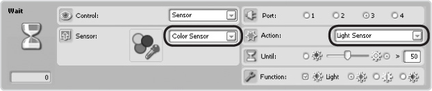
Figure 8-11: The configuration of a Wait block polling the Light Sensor. To configure it, pick a Wait block from the Programming Palette, select Color Sensor from the list of sensors, and then select Light Sensor in the Action box.
defending a territory with the shot-roller
The next program needs a dark room, such as a windowless bathroom with the lights turned off. Once you’ve programmed the Shot-Roller, put it in this room, and you’ll have 30 seconds to leave the room and to carefully close the door. Alone in its darkened room, the Color Sensor’s measure of light intensity should be at or close to 0. Now if you open the door, and once the measured value exceeds 5 (the trigger value), the Shot-Roller robot notices that someone has opened the door and will defend its territory using its shooter. (Don’t forget to close the toilet lid!)
Start a new program called Shot-Roller-Light, and then place and configure the blocks as shown in Figure 8-12.
NOTE When I refer to the Light Sensor, or the Light Sensor value, I’m actually referring to the Color Sensor functioning in Light Sensor mode. When using a programming block to control the Light Sensor, first select Color Sensor from the list of sensors, and then specify that you want to use the Light Sensor function in the Action parameter of the Configuration Panel. In other words, don’t select Light Sensor in the sensor list, because that’s an older sensor that’s not included in the 2.0 kit.

Figure 8-12: The configuration of the blocks in the Shot-Roller-Light program
troubleshooting your program
If your robot doesn’t run the program as expected, the trigger value of 5 in Wait block e may be too low; the room may not be completely dark. Try a higher trigger value, such as 10. (You’ll learn about a more solid solution to this problem in Chapter 9.)
remote-control mode
In autonomous mode, the robot handles all the actions itself, but it is also fun to control a machine like the Shot-Roller remotely. In Chapter 3, you saw that NXT-G has a built-in function to control robots remotely, but it’s suitable only for vehicles like the Explorer. Therefore, you’ll create a program that responds to the remote that you’ll use: two Touch Sensors connected to input ports 1 and 2 on the NXT with long cables, as shown in Figure 8-13.
You’ll use the Touch Sensor on port 1 to control the Turn motor and the sensor on port 2 to control the Turret motor. When you press both buttons at the same time, you’ll make the Shot-Roller fire a ball. Each of these three control actions are placed on a separate Sequence Beam. But how do you control the Turn motor and the Turret motor with just one button each?

Figure 8-13: Two Touch Sensors are used to control the Shot-Roller remotely.
You can solve this problem as follows: The first time you press a Touch Sensor, the controlled motor moves forward until you release the button. Then, when you press the button again, the motor moves backward until you release the button. The next time you press the button, the motor spins forward again, and so on.
Because you want to be able to use the Turret and Turn motors simultaneously, you place the blocks to handle these motors on two separate Sequence Beams so that they can run at the same time.
Create the Shot-Roller-Remote program as shown in Figures 8-14 to 8-20.

Figure 8-14: Step 1: When you press the Touch Sensor on port 1, the Turn motor moves forward, and the Shot-Roller spins to the right. When you stop pressing the sensor, a Motor block makes the motor stop.
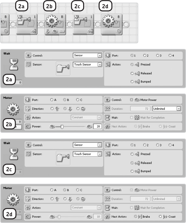
Figure 8-15: Step 2: These blocks work like the ones placed in step 1, except that they make the Turn motor spin backward, causing the Shot-Roller to turn left.

Figure 8-16: Step 3: Place a Loop block on the Work Area, and then select all the other blocks and drag them into the loop. Because of the Loop block, the program will repeatedly wait for button presses and therefore repeatedly control the Turn motor based on this input.

Figure 8-17: Step 4: Select the Loop block that you placed in step 3, and then press the Copy button and then the Paste button on the toolbar to duplicate the loop and the blocks in it. Drag the new loop to the position shown in the figure, and then connect the new blocks to the main program as shown here.
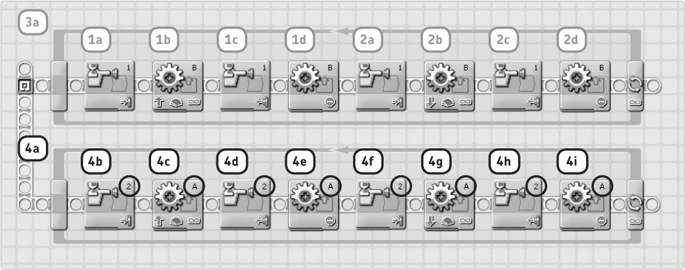
Figure 8-18: Step 4 (continued): The blocks you just copied will be used to control the Turret motor (output port A) with the Touch Sensor on input port 2. Therefore, you change the Configuration Panels of the Wait blocks to wait for button presses of the Touch Sensor on port 2, and you change the Motor blocks to control the Turret motor (port A). Your Work Area should look like the one shown here.
Finally, you need to program the robot to shoot when both Touch Sensors are pressed simultaneously. To do so, you’ll use two Switch blocks, each configured to check whether a sensor is pressed. When both sensors are pressed, the Turret and Turn motors are switched off, and the Firing motor shoots until you release the Touch Sensors.
The Switch blocks are displayed in compact mode (Flat View is not checked in the Configuration Panels) to make the programs more readable. There are no blocks hidden in the false condition tabs of the switches because in this part of the program no action is taken when one of the Touch Sensors is not pressed.
The two switches are placed inside a Loop block so that the robot continuously checks to see whether both sensors are pressed. Because the robot needs to perform this check constantly, you place the blocks that control the Firing Motor on a Parallel Sequence Beam.
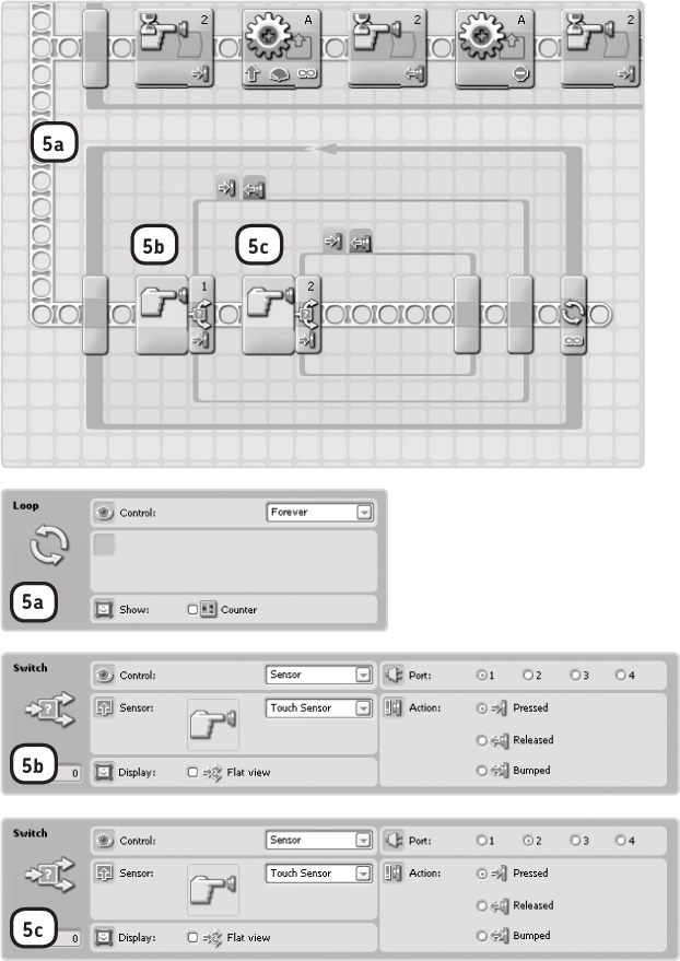
Figure 8-19: Step 5: Place and configure a Loop block and two Switch blocks as shown, and then connect the blocks to the main program by connecting the Sequence Beams, as you did in step 4. Because this is the second Parallel Beam, hold the SHIFT key while making the connection.

Figure 8-20: Step 6: Place and configure three Motor blocks as shown. These blocks are run when the condition of both Switch blocks is true; in other words, when both Touch Sensors are pressed. The Turn and Turret motors are turned off, and the Firing motor starts to fire balls.
Congratulations, you finished creating the remote-control program! Download the program to the Shot-Roller, and have fun!
further exploration
In this chapter, you had a chance to build, program, and play with a prebuilt robot. This is, of course, a lot of fun, but it is even more fun to create your own robot designs. For example, you could take the shooter from this robot and mount it on your self-built car or tank, or you could turn it into a dangerous creature, such as a ball-shooting insect. Don’t worry if you don’t succeed on the first try; you will gain more and more building experience as you continue to try new designs.