
7
using the touch, color, and rotation sensors
Chapter 6 showed you how to use the Ultrasonic Sensor, together with the Wait, Loop, and Switch blocks, to make your robot interact with its environment. In this chapter, you’ll learn how to use the Touch, Color, and Rotation Sensors, as well as the NXT buttons. You’ll use these sensors to allow the Discovery robot to avoid walls with bumpers, follow a line, play different sounds based on sensor readings, and even tell you which color its sensor detects. Once you’ve finished this chapter, you’ll be ready to build two cool robots that use sensors in their own way in Chapters 8 and 9.
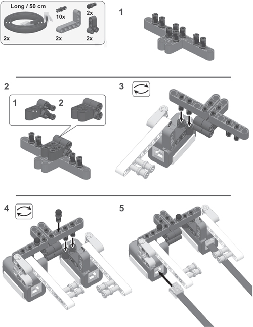
You’ll begin by upgrading Discovery with a dual bumper attachment that use two Touch Sensors, as shown in Figure 7-1.

Figure 7-1: Discovery with a bumper attachment that uses two Touch Sensors
the touch sensor
The Touch Sensor can make your robot feel and respond to its environment by detecting whether its orange button is pressed or not (released). By combining the readings from the Touch Sensor with, for example, a Wait block, you can make the robot respond to a press of the Touch Sensor, as shown in Figure 7-2. The sensor can also detect whether it’s bumped, meaning the sensor was quickly pressed and then released.
You can use Touch Sensors in many different ways. For example, in this chapter, you’ll use them to create bumpers for your robot so that it can back up and turn around when it strikes an obstacle. In Chapter 8 you’ll use Touch Sensors to create remote control buttons, and in Chapter 9 they’ll act as antennas for an animal robot. In Chapter 13 you’ll see how to use a Touch Sensor to perform a specific mechanical function, such as detecting when a grabber has lifted its load to the maximum height.
creating the bumper attachment with touch sensors
You’ll now create an extension for your Discovery robot that uses two Touch Sensors as bumpers (Figure 7-1) to allow your robot to feel objects that it runs into. Once it determines which bumper was pushed, the robot will back up and turn away from this object. Create the bumpers now, as shown in the instructions on the next pages.

Figure 7-2: The Touch Sensor detects three actions: pressed, released, and bumped.


connecting the cables
Now connect the cables that you’ve already added to the Touch Sensors to the NXT, as shown in Figure 7-3.
From now on I’ll refer to the Touch Sensor connected to port 1 as the Right Touch Sensor and the Touch Sensor connected to port 2 as the Left Touch Sensor.
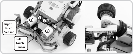
Figure 7-3: Connect the Touch Sensors to the appropriate input ports on the NXT with long cables. To prevent the cables from dragging on the ground or interfering with the wheels, wrap each cable around a motor, as shown here.
programming with the touch sensor
Let’s look at the Configuration Panel settings that are specific to the Touch Sensor, as shown in Figure 7-4.
Use the Port setting to select to which port the sensor is connected.
Use the Action setting to control which action will trigger the sensor (Pressed, Released, or Bumped). When the action occurs, this Wait block stops pausing the program.
creating a test program for the touch sensor
The Discovery-Touch program you’ll create in this section will make the robot play a sound when you press the Right Touch Sensor. Create the program as shown in Figure 7-5, run it, and then create modified versions with each of the other two Action settings (Released and Bumped) so you can see how they work.

Figure 7-4: The Configuration Panel of a Wait block, configured to poll a Touch Sensor. On the right half of the panel are the specific settings for the Touch Sensor. The Configuration Panels of Loop and Switch blocks that control a Touch Sensor contain the same settings.

Figure 7-5: Configuration of the blocks in the Discovery-Touch program
NOTE The Wait blocks on the Programming Palette are basically all the same. The difference between them is that each block has preset Control and Sensor settings to make programming easier.
avoiding walls with touch sensors
The Discovery robot can easily avoid walls with its Ultrasonic Sensor, but it can do the same thing using the Touch Sensors. Although it can’t use the Touch Sensors to sense objects from a distance, of course, it will be able to feel smaller objects than it might otherwise be able to sense with the Ultrasonic Sensor. Another advantage of the two bumpers is that they allow the robot to determine in which direction it should turn after running into something.
When creating your program to use the Touch Sensors, the first thing you need to do is to switch on the motors. Next, you check to see whether a sensor has been pressed. If the Left Touch Sensor is pressed, Discovery should back up, turn right, and then continue its path; if the Right Touch Sensor is pressed, it should back up and turn left. To find out which sensor is pressed, you’ll use Switch blocks.
A Switch block can poll only one sensor at the time, so you’ll start by checking to see whether the Right Touch Sensor is pressed. If it is, you go left. If it’s not, you’ll see whether the Left Touch Sensor is pressed. If it is, you turn right. If neither sensor is pressed, you essentially do nothing different and keep moving forward. All of these actions and decisions repeat continuously, as shown in the schematic overview of the Discovery-Bumper program in Figure 7-6.

Figure 7-6: An overview of the Discovery-Bumper program. If the answer to the first question is yes, the robot turns left, but if the answer is no, another question is asked. The programming blocks that you use to make the second decision are placed inside the lower part of the Switch block that you use to make the first decision.
creating the discovery-bumper program
You’ll now create a wall-avoidance program. First, create a new program called Discovery-Bumper, and place and configure the blocks as shown in Figure 7-7 and Figure 7-8.
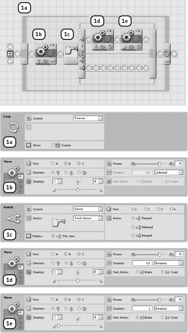
Figure 7-7: Step 1: The blocks shown here turn the motors on and handle the first decision with a Switch block. The complete sequence of blocks is placed inside a Loop block configured to loop forever.
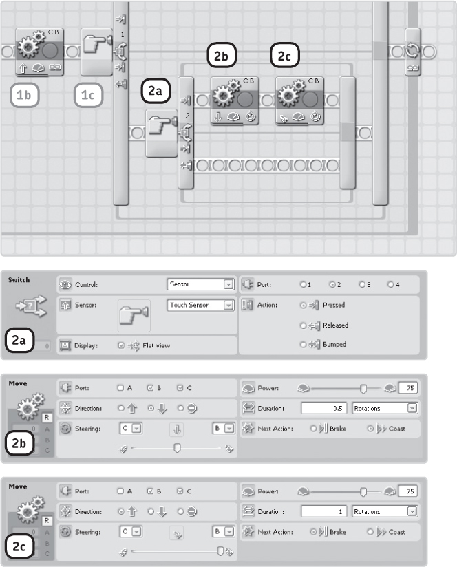
Figure 7-8: Step 2: The blocks you add in this step are run when the Right Touch Sensor (on port 1) is not pressed. The blocks enable the robot to make the second decision. If neither sensor is pressed, the robot doesn’t take any action, and it returns to the beginning of the program to see whether a sensor is being pressed.
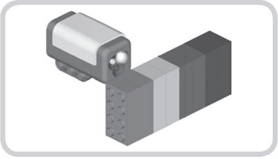
Figure 7-9: The Color Sensor can sense the color of surfaces such as the color of LEGO bricks. It can identify black, blue, green, yellow, red, and white.
the color sensor
The Color Sensor detects the color of a surface, the brightness of a light source, and the intensity of light reflected by a surface. Figure 7-9 shows the Color Sensor being used to detect the color of LEGO bricks. The color sensor can also act as a colored lamp, emitting a bright light colored red, green, or blue. You’ll use the color sensor’s ability to see color in this chapter and learn to use its other features in Chapters 8 and 9.
Because the Color Sensor has so many functions, it’s useful in many applications. For instance, you can use it to make a vehicle follow lines (Chapter 7), as a Color Lamp to indicate that a certain action is taking place (Chapter 8), as a light detector (Chapters 8 and 9), to sort colored LEGO bricks (Chapter 14), and even as a stabilization sensor (Chapter 15).
creating the color sensor attachment
In this section, you’ll enhance Discovery by creating a submodule with the Color Sensor. But before you do, detach the bumpers by disconnecting their cables and the gray pins that connect them. (Don’t take them apart, though; you’ll need them for some of the discoveries at the end of this chapter.)
Once you’ve completed the Color Sensor attachment, connect it to input port 3 on the NXT using the short cable, as shown in Figure 7-10.
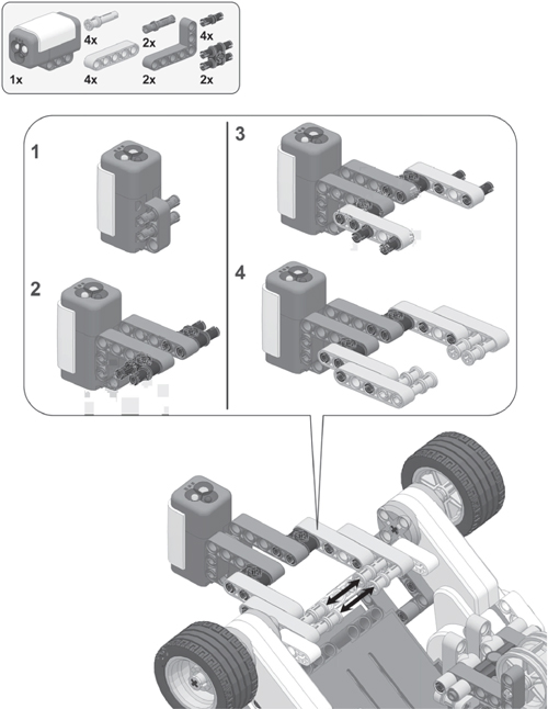

Figure 7-10: Connecting the Color Sensor to the Discovery robot using the short cable

Figure 7-11: The placement of the Discovery robot and the Color Sensor on the Test Pad
using the view mode to poll the color sensor
To poll the Color Sensor, select View▸Color▸Port 3 on your NXT, place your robot on the Test Pad, and point the sensor at the colored line, as shown in Figure 7-11. Notice how the color name displayed on the NXT screen changes as you move the sensor over the line. The sensor can recognize six colors this way: black, blue, green, yellow, red, and white.
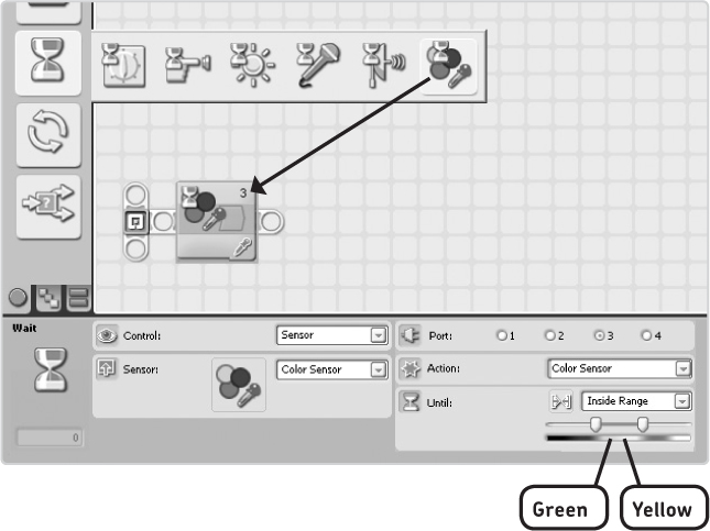
Figure 7-12: The Configuration Panel of a Wait block that polls the Color Sensor
programming with the color sensor
In this section, you’ll create programs for the Discovery robot that use the Color Sensor with Wait and Switch blocks, just as you did with the Ultrasonic and Touch Sensors. Figure 7-12 shows a Wait block that polls the Color Sensor and its Configuration Panel.
In the Port area, select the input port the sensor is connected to (port 3). In the Action box, choose Color Sensor. In the Until box, specify what the sensor should see in order for the Wait block to stop waiting, by selecting a range of colors, such as green and yellow as shown. With Inside Range selected, the robot will wait until the sensor reports a color that is either green or yellow. If you were to select Outside Range, the block would wait until the sensor spots something that’s not green or yellow.
staying inside a colored line
Your next program, Discovery-Circle, will demonstrate how you can use the Color Sensor as a line detector. Once your program is loaded, you’ll place the Discovery robot in the circle on the Test Pad and have it drive around without leaving the circle. Figure 7-13 shows the program flow for this behavior; Figure 7-14 shows how to create the program.

Figure 7-13: The program flow of the Discovery-Circle program
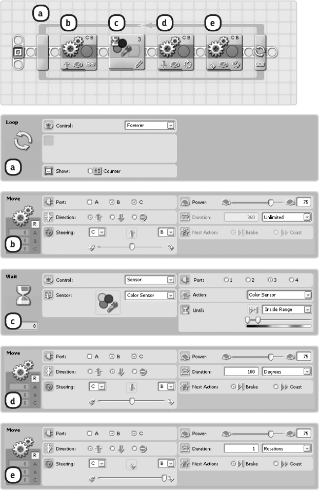
Figure 7-14: The configuration of the blocks in the Discovery-Circle program. The Wait block is configured to wait until the sensor sees something that is black as specified in the Until setting (using the sliding bars).
With the Discovery-Circle program the robot constantly moves through the circle. If you put some LEGO pieces in the circle (Figure 7-15), your robot will eventually push them out, although before it can do that, you need to give Discovery a bulldozer blade. Can you build such a blade with your LEGO pieces?
Figure 7-15: The setup for Building Discovery #4: Using a bulldozer blade, Discovery can sweep the mess out of the circle. Can you build it?
TIP Connect the bulldozer blade to the Color Sensor attachment, and use the Discovery-Circle program.
Difficulty: Hard
You learned earlier that you can use multiple Switch blocks in a program and that the color sensor can detect up to six different colors. Can you create a program that will make the robot say the name of the color it sees, using sound files? To begin, look at the program flow scheme shown in Figure 7-16, and then test your program using the colored bar on the Test Pad. When you’re ready, turn the entire series of blocks (except for the Loop block) into a My Block called Say Color.

Figure 7-16: A model for a program to make the robot say which color it sees
following a line
In your next project, you’ll use the Color Sensor to create a line-following robot, which means the robot will follow a colored track on a mat, such as the black line on the Test Pad. Let’s look at the strategy behind this program.
When following a black line on a white mat, there are always only two possibilities: the sensor measures either white or black. Therefore, when creating a line-following program for a black-and-white environment, you’ll use a Switch block, which looks for the color black. When the sensor sees black, the Switch block will trigger a Move block to perform one movement; if it sees another color (white), it will perform a different movement, as shown in Figure 7-17.
If Discovery sees white, it cannot determine on which side of the line the color lies, so you need to make sure it will always stay on only one side of the line; otherwise, it will stray off the line into the white area. You do this by always driving Discovery right when it sees black and left when it sees white. Figure 7-18 shows the line-following program.
NOTE Be sure when configuring the Move blocks not to drag the Steering slider all the way to the right (in block c) or to the left (in block d), or the robot will turn in place rather than moving forward. Also, be sure that before you start the program, you place the robot on the mat so that the sensor is pointed at the line, with the outside of the circle to the robot’s right (see Figure 7-17a).
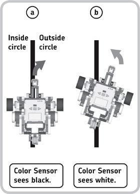
Figure 7-17: Discovery steers right if it sees the black line (a) and steers left if it sees the white area (b). As Discovery steers, it moves forward, so if you repeat this behavior, you end up with a line-following robot.

Figure 7-18: The configuration of the Discovery-Line program. Note that the Duration settings in the Move blocks are set to Unlimited. Once the robot starts to turn, it instantly goes back to the beginning of the program to see whether a different color has been detected or whether it should keep turning in the same direction. Unlimited Move blocks just switch on the motors and have the program continue.
using the NXT buttons as sensors
In addition to the Ultrasonic, Color, and Touch Sensors, the NXT contains its own sensors: the NXT buttons. You can use both the Enter and Right Arrow and Left Arrow buttons on the NXT just like you use Touch Sensors. For example, you can make the robot turn around if you press the Right Arrow button.
To use the NXT buttons, you’ll configure a Wait, Switch, or Loop block set to control a sensor and select NXT Buttons in the Sensor box. In the Button box, choose the Enter Button, Right Button, or Left Button. Finally, in the Action box, you choose whether the button should be pressed, released, or bumped, just as with the Touch Sensor. You can see these configurations in the next sample program.
Let’s practice using these buttons with the Discovery-Button program, as shown in Figure 7-19. Create this program now.

Figure 7-19: The configuration of the blocks in the Discovery-Button program. When you run this program, the robot should turn right when you press the Right Arrow button.
the rotation sensors
When you tell the robot to move forward for three rotations with the Move block, the vehicle knows that it should stop moving when the wheels have each made three revolutions. The robot knows this because the Rotation Sensor in each NXT motor tells the NXT how much the motors have turned.
You can use the information from this sensor in your programs, for example to create a program that repeatedly says “Hello” until you turn one wheel by hand. The sensor tells you how much (either in degrees or rotations) a motor has turned since you started the program, as well as in which direction the motor turned, as shown in Figure 7-20.

Figure 7-20: The Rotation Sensor inside the motor tells the NXT program how many degrees or rotations the orange part of the motor has turned since you activated a program and in which direction. If a program is running and you spin the wheel around twice in the black direction, the sensor will report two rotations (or 720 degrees) in the forward direction. If you then turn it half a rotation in the gray direction, the sensor reports one and a half rotations in the forward direction.
using the view mode to poll the rotation sensor
You can use the motor’s Rotation Sensors in your programs like normal sensors, but since they are inside the NXT motors, they are always connected to output ports.
To use the View mode on the NXT to read the sensor value reported by a Rotation Sensor, turn on the NXT, select View, choose Motor Degrees, and then select port B or C. Now, as you rotate the motor that you selected by hand, the value on the display should change. Positive degree values mean that you turned the wheel forward, and negative ones represent reverse rotations. Instead of Motor Degrees, you can select Motor Rotations to make the NXT screen show how many complete revolutions the wheel has made.
making programs with rotation sensors
As you’ve seen in this chapter, you can use Wait, Loop, and Switch blocks to control a Rotation Sensor. For instance, a program with a Loop block can repeatedly say “Hello” until the motor on port B has turned 180 degrees in the forward direction. The boxes in the right half of the Configuration Panel are used to configure the sensor, as shown in Figure 7-21, and you use the Port box to select to which output port the motor you want to poll is connected. (You’ll learn more about the Reset function in the Action box in “Resetting the Rotation Sensor” on page 84.)
In the Until box you configure the trigger value (the condition that makes a Loop block stop looping) by using the orange arrows to specify whether it should look for forward or backward rotation. Select a number of degrees or rotations, as well as whether the sensor reading should be greater (>) or less (<) than this number in order to trigger the block and make the Loop block stop Looping.
Now create the sample program Discovery-Rotation shown in Figure 7-21 to perform the behavior described.
NOTE The list of sensors in the Wait, Loop, and Switch blocks may contain both Rotation Sensor and !Rotation Sensor. The !Rotation Sensor is there for compatibility with older versions of the NXT-G software, but you’ll always use the Rotation Sensor option (the one without the exclamation point) in this book.
resetting the rotation sensor
As a program runs, the Rotation Sensor value changes as you turn a motor by hand or if a Move block makes the robot move. Sometimes, though, it is useful to reset this value to zero. For example, you might want to modify the Discovery-Rotation program to reset the sensor after it confirms that the motor has turned 180 degrees. With a Loop block and the Action setting specified to Read, the Rotation Sensor will repeat the blocks in it until the trigger value is reached. When Reset is selected, the sensor value is reset to zero after each loop. Therefore, a Loop block with this setting stops only if the trigger value is reached during one loop.

Figure 7-21: The configuration of the blocks in the Discovery-Rotation program. Experiment with this sensor by changing the settings in the Until box of the Loop block to see what each setting really does.
Difficulty: Medium
The program shown in Figure 7-22 plays different tones depending on how the left and right wheels of Discovery are rotated. If a wheel is turned forward, the robot plays a different tone than when it is turned backward. Can you figure out how this program works and how it is configured?
HINT The hidden tabs of the Switch blocks also contain Sound blocks.
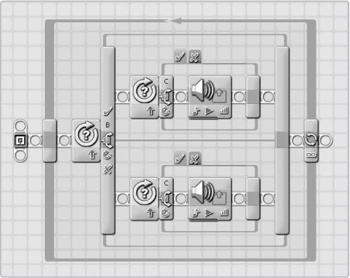
Figure 7-22: Can you re-create the program shown here? How do you think the blocks should be configured to make the robot play four different tones depending on how the wheels have turned?
Now modify the Discovery-Rotation program. Change the Action setting to Reset, and run the modified program to see how this works.
NOTE If you select Reset in a Switch block, the value is reset to zero after the sensor value is compared to the trigger value. You cannot reset the sensor value with a Wait block.
further exploration
Now that you’ve learned how to work with the NXT sensors, you should be able to create robots that interact with their environments. Discovery is, of course, only one example. As you continue reading this book, you’ll build several robots with sensors, each of which will use sensors differently.
By now you’ve learned to use the components that are essential to create a working robot: the NXT, the motors, the sensors, and the NXT-G software. The following chapters will explore each of these subjects in more detail so that you’ll be able to create increasingly sophisticated (and fun!) robots.
The following discoveries will help you explore more possibilities with the sensors. Be sure to post your ideas and solutions to the book’s companion website (http://www.discovery.laurensvalk.com/)!