
11
using data blocks and using data wires with loops and switches
Now that you know how data wires work, you can do some really interesting things with more of the programming blocks. You can use some of these new blocks to make the NXT combine and process sensor values so that they can be used as input values for other actions. For example, with the tricks learned in this chapter, you’ll be able to program your robot to do something only when two sensors are triggered at the same time or to do things randomly, rather than performing a series of preprogrammed actions.
In this chapter I’ll show you how to do math on the NXT with the Math block so that you’ll be able to have your robots calculate, for example, the distance to travel based on a sensor reading. I’ll also introduce you to a few new data programming blocks such as the Random, Compare, and Logic blocks as well as a few new techniques to use with the Switch and Loop blocks, by providing sample programs and new discoveries.
These techniques and programming blocks are essential to advanced robot programs like the ones you’ll create in Part IV, as well as for advanced programs that you’ll create for your own robots. As in Chapter 10, you’ll use the SmartBot to test your new programs.
The discoveries in this chapter might not seem so interesting at first, but once you’ve mastered many of the essential programming skills by solving them, you’ll be able to create much more interesting programs for your robots and build some really smart robots!
data blocks
The Complete Palette contains a series of blocks that you have not used yet: data blocks. Data blocks (Figure 11-1) include the Math block, the Random block, the Compare block, and the Logic block. Each block has its own function, but they all process values carried by data wires and generate new values based on the input values. This section will explain how to use these blocks in your programs.
the math block
The Math block allows the NXT to do arithmetic operations such as addition, subtraction, multiplication, and division. In its Configuration Panel, you can fill in placeholders for two numbers (A and B), and choose which operation should be applied to them, such as multiplication (A will be multiplied by B). The result is output with a data wire. When you use the Math block, you’ll often transfer one or both numbers to the Math block with a data wire instead of entering them yourself, as you’ll see in the second sample program in this chapter.
The Smart-Math program in Figure 11-1 shows the Math block performing a multiplication. The Number to Text and Display blocks are used to display the result on the NXT screen.
Now you’ll learn how to use the Math block in programs for your robots to do more than just display a value.
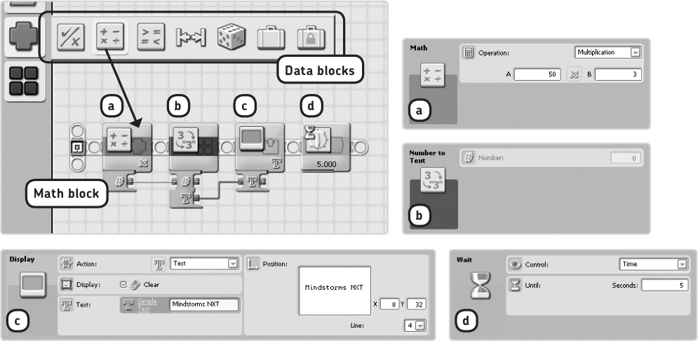
Figure 11-1: The Math block in the Smart-Math program multiplies 50 by 3 and displays the result (150) on the NXT screen. (I’ve hidden the unused data plugs to make the program easier to understand.)
using the math block in a more advanced program
The Sound block can play tones at specific frequencies: The higher the frequency, the higher the pitch you’ll hear. You’ll use the Sound block to create a program that plays tones that change based on readings from the Color Sensor. Your robot will repeatedly play short beeps, depending on which colored ball (from your robotics kit) is held in front of the sensor.
To make this program work, you’ll have the Color Sensor block send sensor values to the Sound block with a data wire connected to the Detected Color plug (which outputs a value between 1 and 6 depending on the detected color). To have the Sound block play tones at a frequency that you specify, you transfer the sensor values to the block’s Tone Frequency plug. If the block receives small values (around 250) from the data wire, it plays low buzzes. Large numbers (around 4,000) make the block play high pitches.
As you can see, this data plug requires fairly large input values. However, since the Detected Color value ranges between 1 and 6 (not 250 and 4,000), you need to process the reading somehow so it can be used as input to the Sound block. To accomplish this, you’ll use the Math block to multiply the color value by 250. For example, if the Color Sensor sees blue, the sensor value is 2, and the Math block will multiply it by 250. The result is a frequency of 500, which will make the Sound block play a low tone. You’ll hear a higher sound when the sensor sees a red ball (frequency = 1250). Create the Smart-Sound program shown in Figure 11-2 now.
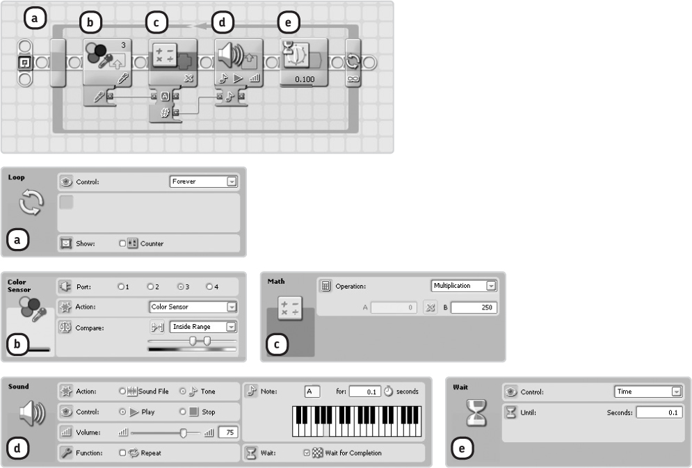
Figure 11-2: The Smart-Sound program. Instead of filling in two numbers in the Math block’s Configuration Panel as in the previous program, you feed one value to the block with a data wire.
Difficulty: Medium
Create a program that continuously displays the Light Sensor and Ultrasonic Sensor readings, as well as the sum of the two, on the NXT screen, as shown in Figure 11-3. Use a Math block to add the two readings, and add a Wait block configured to wait for 0.5 seconds (in the Loop block) so that you’ll have enough time to read the display.

the random block
You use the Random block to generate a random number for use in your program. Use the block’s Configuration Panel to select a range for the random number, such as 35 to 47. The Random block will output the random value through a Number data wire, which in this case will be 35, 47, or some value within this range.
The Random block is useful when you want your robot to do something unexpected. For example, you could use a Random block to make the SmartBot’s Wheel motor turn at a random motor speed, as shown in the Smart-Random program in Figure 11-4.

Figure 11-4: The configuration of the Smart-Random program. The Random block generates a random value between 0 and 100, which is carried to the Power plug on the Motor block, switching on a motor. Next the program waits until you bump the Touch Sensor, at which point the loop returns to the beginning, and the motor speed changes to a new random speed.
the compare block
The Compare block checks to see whether a value is greater than (>), less than (<), or equal to (=) another value. You can enter the values you’d like to compare in the Configuration Panel, or you can supply the values to the block with data wires (plug A and plug B).
The Compare block outputs one Logic data wire (true or false), based on the result of comparing value A to value B. For instance, if you set Operation to Equals, the block outputs true if value A is equal to B.
The Smart-Compare program in Figure 11-5 shows the Compare block in action. In this program, the Random block sends a random value (0, 100, or somewhere in between) to the Compare block, which checks to see whether this value is less than 50. If it is, the Wheel motor on Smart-Bot spins forward for one rotation; if not, it turns backward. This behavior repeats, and the motor continues to revolve in random directions as the random values change.
the logic block
In some of your programs you’ve used Sensor blocks to determine whether the Touch Sensor was pressed or whether the Ultrasonic Sensor value was bigger than the configured trigger value. The results were carried away from the blocks with Logic data wires.
You can use the Logic block to compare two Logic data wires. Depending on how you configure the block, it can see whether both wires carry the value true. If so, it will output a value true. If none or just one of the two input values are true, its output value will be false.
You can use a Logic block to create a program that turns on the Color Lamp if both the Touch Sensor is pressed and the Ultrasonic Sensor sees something farther away than 100 cm. If either or both conditions do not occur, the Color Lamp is switched off, because the Logic block’s output is false. Figure 11-6 shows the Smart-Logic program.

Figure 11-5: The Smart-Compare program. The Compare block in this program checks to see whether the Random block’s output (between 0 and 100) is less than 50. If it is, the Compare block’s output value is true, and the Wheel motor on the SmartBot turns forward. If not, the output value is false, and the motor turns backward.
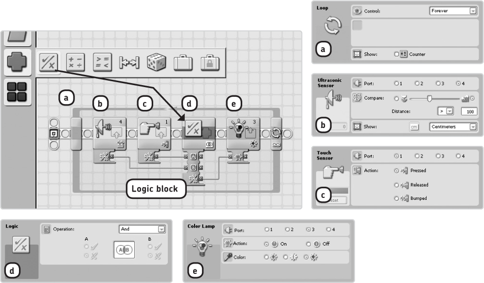
Figure 11-6: The Smart-Logic program. If the Touch Sensor is pressed and the Ultrasonic Sensor sees something that is farther away than 100 cm, the lamp on the Color Sensor is switched on. Because you use the results of the compare and action functions within the Sensor blocks, you connect the Logic data wires to the Yes/No output plugs on the data hubs. (I’ve hidden the other data plugs, such as the Distance plug on the Ultrasonic Sensor block.)
logic operations
When configuring the Smart-Logic program, you can select from four operations in the Logic block’s Configuration Panel: And, Or, XOr, and Not. Each option will make the block compare the two logic input values differently, as you’ll learn in a moment. The option you choose will depend on what you want your program to do.
Table 11-1 lists the available operations, as well as the input values that would lead to an output value of true with each of the operations. (The Smart-Logic program uses the And operation.)
table 11-1: the operations of the logic block and their output values
Operation |
Output value is true when . . . |
And |
Both inputs are true |
Or |
One or two inputs are true |
XOr |
One input is true and the other is false |
With these operations, you wire the two Logic data wires to be compared to the A and B input plugs of the block, but it doesn’t matter which wire you connect to which plug.
not operation
When you select the Not operation, the Logic block doesn’t compare two Logic data wires; it only does something with the logic value wired into plug A on the data hub. This operation just inverts the input signal: If the input A value is true, the output will be false; if the input A value is false, the output will be true.
switch blocks and data wires
You’ve used the Switch block to enable a program to make decisions, such as to determine whether a Touch Sensor is pressed. As a quick reminder, see Figure 11-7, which shows a Switch block in action. Recall that a condition is a statement like “The Touch Sensor is pressed.” When the Switch block determines that a Touch Sensor is being pressed, the condition is true, and the blocks on the upper half of the Switch block are run. If the condition is false, meaning the Touch Sensor is not pressed, the blocks on the lower half of the Switch block are run instead. (See Chapter 6 to learn more about the basics of Switch blocks.)

Figure 11-7: The Smart-Touch program continuously checks whether the Touch Sensor is being pressed. If it is, the Color Lamp blinks (it’s switched on and off). If not, the robot says “No.”
configuring switch blocks with data wires
In addition to working with sensor readings, a Switch block can also make decisions about values when a data wire is connected to the Switch block.
For example, you could configure a Switch block so that the blocks in its upper part run when the input value signal is true and so the blocks on the lower part run when the input signal is false. To do this, you connect a Logic data wire to the Switch block.
To be able to connect a data wire to a Switch block, you’ll select a Switch block from the Programming Palette, place it on the Work Area, then set the Control parameter on its Configuration Panel to Value, as you’ll see in the Smart-Switch sample program that follows.
Smart-Switch displays a random number between 0 and 100 on the NXT screen and also displays whether that number is greater or less than 40. The program first generates a random number between 0 and 100. Next, with the aid of a Compare block, it checks to see whether that number is greater or less than 40. If greater, the Compare block’s output value will be true; otherwise, it will be false. A Logic data wire transfers this value to a Switch block. If the Switch block receives a value of true, the upper parts in the switch are run; if the value is false, the lower blocks are run.
You’ll find the Smart-Switch program in Figure 11-8 and Figure 11-9.
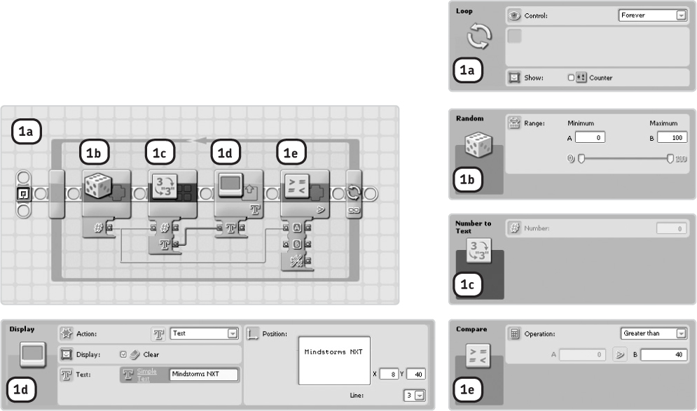
Figure 11-8: Step 1: Because the complete program repeats continuously, you place all of the programming blocks inside a Loop block. The other blocks shown here allow the robot to display the random number on the NXT screen. That same random number is also sent to a Compare block, which checks to see whether it is greater than 40.
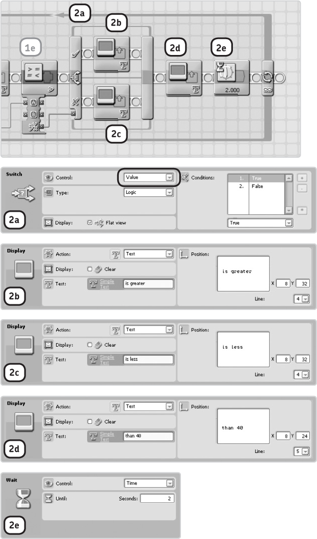
Figure 11-9: Step 2: If the value is greater than 40, a true signal is sent from the Compare block to the Switch block, causing the Display block in the upper part (in V) of the switch to be run. If the signal is false, the lower block (in X) is run. The next Display block (2d) in this step completes the line that is eventually displayed on the NXT screen. Every two seconds your screen will show a new line like 26 is less than 40. The Wait block gives you enough time to read the display before the loop repeats.
using number and text data wires and switch blocks
Rather than wiring a Logic data wire into a Switch block, you can use Number or Text data wires. When using Number data wires, you could have blocks on the upper part of the switch run when the data wire value is, say, 5, and have the lower part run when the value is 3. The process is the same for Text data wires, except that when using them, you’ll use text instead of numbers. You won’t use this feature in this book, but if you want to learn more about it, you can refer to the NXT-G help section for the Switch block.
connecting data wires to inside switch blocks
In some cases it can be useful to connect data wires from outside a Switch block to blocks inside the switch, as shown in Figure 11-10. For example, you can do so when you want to use an Ultrasonic Sensor value outside the switch that you also want to use with a block inside the switch, without having to poll the sensor again. To do so, uncheck Flat View, and then connect the data wires. With Flat View turned off, click the condition icons to swap between the switch’s two Sequence Beams.
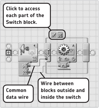
Figure 11-10: You can connect data wires from outside a Switch block to blocks inside it only when Flat View is turned off. The program shown here polls the Ultrasonic Sensor to compare its reading to a trigger value. If the result of the comparison is true, the motor is switched on, at a power level based on the Ultrasonic Sensor reading. Because there are no blocks in the other part of the switch, when the result of the comparison is false, nothing happens.
loop blocks and data wires
Previously when you’ve used Loop blocks, you’ve typically configured them to loop forever, causing the blocks inside the loop to repeat until you manually abort the program. You can also configure loop blocks to loop a certain number of times, to loop a certain number of seconds, or to repeat the blocks inside the loop until a sensor is triggered. You can also end a loop with a data wire.
When you set the Control parameter in the Loop block’s Configuration Panel to Logic, you’ll see an input plug on the right side of the Loop block, and you can connect a Logic data wire to this plug. Now you can specify whether the Loop block should stop looping when this plug receives a true or false logic value, as demonstrated in the Smart-Loop program in Figure 11-11. While looping, the program continuously checks to see whether the Touch Sensor or the Enter button on the NXT is pressed. If one or both are pressed, the Logic block outputs a true value. Because the Loop block is configured to repeat the blocks inside the loop until it receives the true signal, it ends when a sensor is pressed, and the Sound block has the NXT play a sound.
Create the Smart-Loop program now as shown in Figure 11-11. Smart-Loop is a very useful programming construction, because it has the program wait while checking two sensors. It actually functions like a Wait block, except that a Wait block can poll only one sensor.

Figure 11-11: The configuration of the blocks in the Smart-Loop program
Difficulty: Easy
With the Smart-Loop program you learned how to create a program that pauses until one of two sensors is triggered. By adding some extra blocks, you can even poll three sensors (or more) at one time. Create a program that will make a sound when you press a button (either the Left Arrow, Right Arrow, or Enter button) on the NXT. You can see how to do this in Figure 11-12, but this program isn’t finished yet. Can you connect the data wires and select the right operation in the Logic blocks to make it work?

further exploration
In this chapter you learned about several data programming blocks, as well as some tricks for using data wires with the Loop and Switch blocks. These techniques will allow your robot to process and combine sensor values in order to use them as inputs for actions such as making sounds or moving. You’ll see practical examples of this in the next three chapters of this book. For now, practice your newly acquired skills in the following discoveries.