Chapter 1. Introduction to the Method
IDEFO is the most useful method of communication in my professional bag of tricks. This is a more radical statement than it may seem at first, considering that I count various programming languages (FORTRAN, Ada, and assembly code, for example), numerous software design methods (Yourdon, Parnas, and so on), multiple spreadsheet applications (such as Lotus and Excel), and the English language itself as other methods in this “bag.” How can this be? It would seem that the English language would be the most valuable to me—it is, after all, my native language—but IDEFO plays a unique role in my ability to communicate with people in my line of work.
Communication with IDEFO
Using IDEFO, I can communicate and validate my understanding of complex technical subjects of which I had little previous knowledge. It is the most effective way I know of to communicate with technical and nontechnical people, including management, and it plays a vital role in bridging the communication gap between these two groups. Prior to learning IDEFO, I would get mired in hundreds of pages of system specifications and even larger government requests for proposals (RFPs). Now, using the IDEFO method, I can handle complexity without having to rely on the English language alone.
Overview of IDEFO Syntax
The graphical elements of IDEFO are very simple—just boxes and arrows. The boxes represent actions; the arrows represent interfaces between those actions. Figure 1-1 illustrates how IDEFO syntax depicts a basic message in a simple IDEFO diagram. The figure shows that the activity SELL PRODUCTS produces Cash, which is either deposited in a checking account or used to PAY BILLS.1 Note that the Cash shown on the arrows represents physical cash, not information about the cash, as would be shown in a data flow diagram. IDEFO diagrams present all manner of things on the data arrows—anything that is used by, is created by, or influences an activity.
1 As a style convention, in this paragraph I use initial caps to signify interfaces between actions, with the actions themselves set in small caps. For the sake of readability, I will use this convention only when unavoidable.
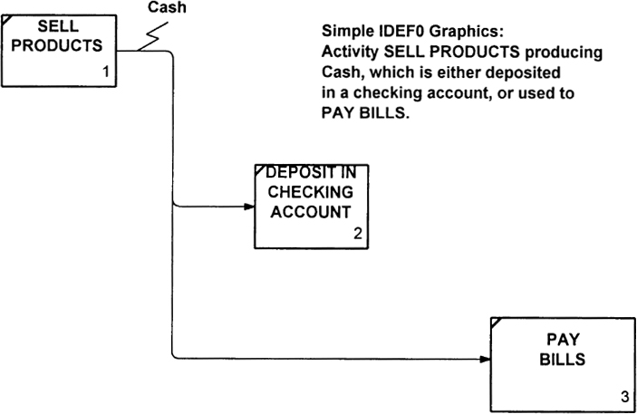
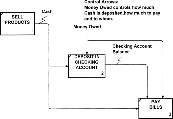
Figure 1-2 shows the addition of control arrows to boxes 2 and 3 of the same diagram. The control arrow Money Owed represents outstanding bills and therefore controls how much may be deposited versus how much should be retained to pay bills. Figure 1-1 assumed that the bills are paid in cash—an assumption drawn from the “story” of the diagram. The addition in Figure 1-2 of the control arrow Checking Account Balance shows that bills may be paid by check.
Finally, Figure 1-3 shows the addition of IDEFO mechanisms to the same diagram. We see that Bank is a mechanism required to make a deposit. Deposit Tickets are also needed, and the diagram indicates that these two mechanisms are used to deposit money in an account. The diagram also shows that both Deposit Tickets and Blank Checks are obtained from the Checkbook, and that Blank Checks are used to PAY BILLS, whereas Deposit Tickets are used to put Cash in the Bank.
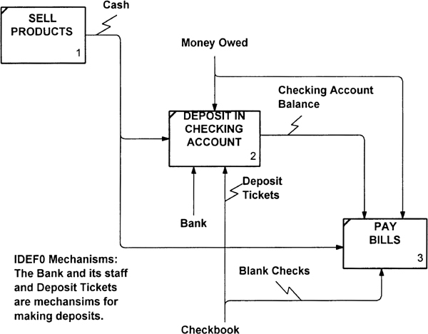
The simplicity of the graphics assumes that one of the major benefits of IDEFO—its ability to communicate to nontechnical and technical enterprise staff alike—will be upheld. Note how the four sides of an IDEFO box support the reader’s intuitive sense. Arrows entering the top of the box imply control (coming down on the activity and enforcing rules). Arrows entering the left side and producing data out the right side of the box imply an input-output relationship. Mechanism arrows coming into the bottom of the box imply a sense of support for the activity.
The communication power of IDEFO provides an efficient and precise way to model real-world operations. Even without any training in IDEFO syntax and semantics, anyone looking at these figures can understand the “story” being depicted. Attempts to elaborate on the IDEFO syntax, such as adding AND/OR logic branches to arrows, different arrow syntax for different classes of arrows, and so on, all result in unacceptable complication of the diagrams and a failure to communicate effectively.
I discuss IDEFO syntax and semantics in greater detail in Chapter 4. For now, to give the reader a feeling for the value of IDEFO and to highlight its real contribution, I devote the next section to a brief history of the method.
Origins and History of IDEFO
As a graduate student at MIT in 1957, I worked under Douglas T. Ross at the Servomechanisms Laboratory (later to become the Electronic Systems Laboratory). Sometime before my arrival, Ross’s lab had developed the first “numerically controlled machine tool” (a computer-controlled milling machine whose motions were controlled by a computer rather than by a machinist following a template) under a government-sponsored research contract with the Air Force Manufacturing Technology (ManTech) initiative to support the United States aerospace industry.
About the time I arrived, Doug Ross was starting a new project to develop a computer support system for programming this new milling machine, relieving programmers from developing lengthy and costly binary machine tool tapes by hand. Although I was not aware of the fact at the time, this was to be the first problem-oriented language in which the programmer wrote instructions to the computer in the user’s technical language, rather than having to learn assembly code or FORTRAN (which was just being developed). The users were able to tell the computer, “Turn on the coolant,” “Move in a straight line from point A to point B,” “Retract the tool,” and so on, instead of “If location A contains a 0, then set A equal to B.” Clearly, weeks of work preparing a single tape could be reduced to a matter of minutes with this new computer language interpreter.
But this accomplishment is not the real issue here; the important point is to realize that this was a true breakthrough in communicating between one technical discipline and another—between the world of the computer programmer and the world of the machinist. Both were technically trained, but in different worlds, using different jargon, and having unique backgrounds and experiences that made them experts in their own diverse ways.
Now, turn the clock to the late 1960’s. The numerical control industry had adopted the MIT system (called APT, for Automatically Programmed Tool) as a national and international programming standard. The same Air Force ManTech Office was attempting to help modernize and upgrade the aerospace industry’s manufacturing capabilities in other ways. However, ManTech personnel were under heavy criticism for providing technology upgrade funds for a single aerospace manufacturer while being unable to provide equivalent support to all of the other aerospace companies.
Recalling their prior experience with APT, in which a coalition of aerospace companies cooperated with MIT to develop, distribute, and maintain the system, the Air Force once again turned to Doug Ross to suggest how it might develop support systems that could be used by an entire industry rather than a single company. Ross had long viewed the universe by looking at complex phenomena and applying the divide-and-conquer approach to decompose them repeatedly until each piece of the model was simple enough to understand and analyze. Consequently, Ross’s answer to the Air Force’s request was to develop an industry-wide model of how aerospace products are built and then to develop support systems that could be used by all (an open-system concept similar to that used today to build printers and monitors to be plug compatible with products from other personal computer manufacturers).
Ross’s idea was accepted by the Air Force, and the Air Force Computer Aided Manufacturing (AFCAM) program was funded. This initial experiment was conducted in Seattle at Boeing, the company selected as representative of all aerospace operations. However, because the conglomeration of aerospace companies would only accept the result if developed by a coalition of the entire industry, it was not until 1978 that an industry-wide model was developed using Ross’s modeling concept, and the Integrated Computer Aided Manufacturing (ICAM) contract was awarded to SofTech, Inc. (the company Ross had founded after leaving MIT).
An Early Opportunity
During the five years preceding the award of the ICAM contract, Ross’s modeling method was applied to a commercial effort in a very different technical field, that of telecommunications. At that time, International Telegram and Telegraph Company (ITT) was developing specifications for the so-called Telephone System of the Future, which included call waiting, call transferring, and many of the other features that we take for granted today. ITT had a large specification effort going on in Europe for the new system, and the project was behind schedule. Experts from five countries were developing the specification, and they had reached an impasse. Documents in English, German, Spanish, French, and Italian sat on shelves in the ITT headquarters in Paris, and no one could determine whether information for different parts of the specification was complete, accurate, or compatible.
The solution was to reanalyze the subject using Ross’s graphical modeling “language.” The goal of the project was to identify elements missing from the specification and errors in the logic while analyzing the completeness and compatibility of the various components. A secondary goal was to provide a communication baseline between all parties. Because the job was too big for one small group of analysts, training courses were given throughout Europe to teach ITT staff how to do the modeling.
The ITT effort successfully pointed out problems in the existing specification (for example, where one group erroneously assumed that a second group was responsible for a portion of the analysis), and analysts from all five countries were able to communicate technical concepts and coordinate the interfaces between their parts of the planned system. Software specifications were written for portions of the renewed effort that was to follow. The Ross modeling method proved itself undeniably effective.
A Good Name
Another significant event took place at ITT’s Paris headquarters during that same period. The manager of the ITT effort, Don Combelic, recognized the inherent usefulness of Ross’s approach, and he decided that the modeling method needed a good name. He described the method as a structured analysis and design technique, and coined the term SADT. His intention was to show that the method was useful not only for analysis, but also for design, and he pointed out that the most important and innovative feature of the method was traceability—the ability to trace each user function back to the design element that implements that feature. Thus, using a mechanism arrow syntax, each user function was traceable to an element of the software, and no software element would be included that had no purpose from the user’s perspective. This was a major advantage in ensuring complete and accurate communication between the nontechnical user community and the technical hardware or software development community.
Combelic required that the principles behind SADT modeling be documented (see the Seven Basic Principles, in Chapter 3), and also insisted that quality assurance issues be addressed, asking for specific methods for judging model quality.
By 1978, as mentioned earlier, the AFCAM effort in the United States was refunded and called ICAM, and a coalition of aerospace companies began developing the industry model of how they worked. They discovered that one company’s product “breakback” structure was similar to a second company’s “breakdown” structure, and that both were specialized forms of the common manufacturing document called a bill of materials. The model showed how these key elements were used and communicated during different parts of the manufacturing process, thus providing a greater level of understanding and management control. A follow-on project was then started to perform a similar analysis on the design portion of the aerospace operation, which complemented the manufacturing portion just completed.
A Series of Methods
By 1981, the Air Force recognized the usefulness of the modeling method and requested a formal Air Force version. The ManTech Office in the Air Force’s Materials Laboratory expanded the concept to include a series of IDEF methods, naming the function-analysis portion of SADT that they found most useful “IDEFO.”2 A second method, named IDEF1, was developed for analyzing data and building databases.3
2 For a more detailed discussion of the history of and relationships between SADT, IDEFO, and IDEF1X, see Appendices C and D.
3 IDEF3, a process analysis technique, has also been added; IDEF2 (using a simulation analysis approach) is not yet a formal member of the IDEF family.
The acronym IDEF (ICAM Definition) describes a series of methods for developing ManTech products and integrating them into the daily operations of an enterprise. By decree, all IDEF methods are in the public domain, are freely available for use without any proprietary rights or licensing requirements, and may be used to define and integrate ManTech products. To date, three IDEF methods are supported by the Air Force and by United States industry; eleven additional methods are in some stage of research or development.
The full IDEF set (IDEFO, IDEF1, IDEF3) was designed to support systems analysis, where a “system” may be a computer system, a noncomputerized process, or an entire enterprise. Because IDEFO by itself had demonstrated the ability to handle an enterprise’s comprehensive scope and complexity, it was the first of the set of IDEFs to be applied to large enterprise analysis. IDEF proponents called IDEFO a “methodology” because of its comprehensive nature, intending the term to signify that IDEFO includes procedures for specifying its application and for accomplishing specific goals, and to convey that it was more than a mere technique or language. This use of the term “methodology” has become widespread among the IDEF user community, but I prefer to use the word “method” to describe IDEFO. My reasoning is that, strictly speaking, adding the suffix “ology” denotes “a study of,” making a methodology a meta-view of methods. To me, methodologies consist of ways for describing and defining methods, which is not the usage of the term adopted by the IDEF project. Rather than quibble over terminology, I use the word “method” to describe elements of the IDEFO approach.
The division of the analysis phase into function (IDEFO) and data (IDEF1) took place during the ICAM program, and had the unfortunate side effect of causing camps to form among the analysts. The database camp viewed the world as a giant database, and argued that the only way efficient computer systems could be developed was if everyone adopted this viewpoint. The functional analysis camp insisted that data are useless unless one can see their functional purpose. This debate continues today, but may be swallowed up by the object-oriented approach, in which both function and data are combined into “objects.”
Armed with these observations, we can now look more closely at the development of IDEFO to see how the IDEFO enterprise analysis approach is designed to satisfy the needs demonstrated by the ICAM and ITT experiences.
Elements of IDEFO
The IDEFO method is comprised of three major elements based on the use of developing and using a model of the real world. The three elements of IDEFO are concepts, language, and pragmatics.4 This book describes IDEFO in terms of these three distinct aspects, and shows students of the method that the maximum benefit from IDEFO comes from understanding and using all three elements.
4 The word “pragmatics” was first used by Doug Ross to describe the key procedural aspect of the method, and is the word used by all IDEF modelers to describe practice and procedures.
The concepts are at the foundation of IDEFO. They are ideas that the user of the method should believe in and adhere to if the rest of the approach is to make logical sense. These concepts are defined as the seven basic principles of IDEFO, and are presented in Chapter 3. They answer why one approach is used over another in the application of IDEFO, and they provide the experienced analyst with the rationale for following the rules, including when to bend them and when strict adherence is important.
The language of IDEFO is the analyst’s means of describing the activities of an enterprise. The language is written in graphical box-and-arrow notation on diagram forms that are structured to produce IDEFO models. The language is used to convey meaning between the analysts, readers, enterprise management and staff, and others.
The pragmatics of IDEFO provide the engineering procedures for using IDEFO. In many cases, the pragmatics are so closely tied to the concepts and language that they are inseparable, and analysts who have attempted to use IDEFO without employing them typically have been unsuccessful. (When I present the most common misuses of IDEFO, later in this book, I show the kinds of problems that can occur if the pragmatics are not followed.5)
5 It is informative to note that during the development of the FIPS (Federal Information Processing Standard) for IDEFO (FIPS 183), there was a lengthy discussion with the National Institute of Standards and Technology (NIST) about the inclusion of a pragmatics section in the Federal Standard. The authors were apparently not familiar with standards that included a pragmatics section. Because of this, and because of the foreseen difficulty with creating such a section of the standard, the IDEFO pragmatics were not included in the “Normative” (required) section of FIPS 183, but were relegated to an “Informative” appendix. This appendix may or may not be referenced when determining if a specific use of IDEFO does or does not comply with the FIPS 183 standard, as the user of the standard wishes.
It is also interesting to compare the IDEFO FIPS with that of Ada, FORTRAN, and other existing standards. Here, the definition of the language syntax and semantics are included in the standard, but there is no mention of how to use the method. Similarly, the developers of the IDEF1X FIPS (FIPS 184) did not find a need for a pragmatics section, claiming that it did not matter how users developed the IDEF1X data model so long as the resulting graphics obeyed the standard syntax and semantics.
To be effective, the IDEFO method must be able to handle complexity. Therefore, behind the concepts, language, and pragmatics lies a basic principle: Divide and conquer. This principle assumes that any amount of complexity can be handled if it is broken down into small enough pieces, so long as the pieces are rigorously linked. This process has long been used in manufacturing. For example, in the aerospace industry, a modern aircraft includes more than three million individual parts. To understand this level of complexity, a designer breaks down the aircraft into its hydraulic system, its electrical system, and so on. So long as these individual parts work correctly and are integrated into the overall system, the aircraft’s complexity is not a major problem.
Doug Ross stated the divide-and-conquer principle as an axiom:
EVERYTHING WORTH SAYING ABOUT
ANYTHING WORTH SAYING SOMETHING ABOUT
CAN BE SAID WITH SIX OR FEWER PIECES.
Applying this principle to the modeling of systems, we begin an IDEFO model with a high-level, single activity that represents the whole system. Breaking this into six or fewer pieces results in a diagram containing six or fewer activities and their interfaces. Each of these activities is then broken down into six or fewer sub-activities on decomposition diagrams.6 This process is repeated until sufficient detail is presented to satisfy the purpose of the model.
6 The word “decomposition” conveys the form of breakdown used in IDEFO. An activity is decomposed into the elements that comprise it (as opposed to applying it in different environments, using it at different time phases, and so forth).
Following the divide-and-conquer principle thus results in a gradual exposition of detail as each activity decomposition diagram is studied by the reader. Each activity box on a diagram represents a well-defined context that sets the scope of the decomposition. This is a key in the communication power of the IDEFO models, since the reader may study any aspect of the modeled system and explore finer detail about an activity of his choice.
Use of IDEFO with Other Methods and Tools
Despite the mass of evidence reflecting successful IDEFO application, the method still has not been widely accepted. In my view, there are two basic reasons for this: misuse and misconception.
Misuse of the method has been the focus of panel sessions at several IDEF Users Group conferences and is, in fact, such an important topic that I devote a whole chapter to the do’s and don’ts. Chapter 6 also presents specific examples of the misuse of IDEFO and describes ways to correct the problems. A discussion of the major misconceptions is presented below.
Misconceptions about IDEFO abound. Some stem from the origins of the method with the Air Force’s ICAM program. Key misconceptions concern the scope and topics that can be modeled, IDEFO’s role in the system development life cycle, its ability to be used in conjunction with other methods, IDEFO’s use with CASE (computer-aided software engineering) and other analysis and development tools, IDEFO’s application to systems analysis, and finally, the belief that an analyst can create useful models with no IDEFO authorship training or apprenticeship period. The following sections address these key issues in terms of IDEFO’s relationship with various aspects of system development.
IDEFO and Scope of Application
I’m often asked the question: “To what types of problems can IDEFO be applied?” People think that since IDEFO was developed as a means of depicting manufacturing processes, IDEFO’s scope must be limited to manufacturing process models. This is not the case: The theoretical basis of IDEFO is that it can be used to model any system comprised of things and happenings. This is a very broad scope; it is difficult to think of any subject to be modeled that contains no action or has no things to act on. Therefore, IDEFO is perfectly applicable to such topics as strategic planning, project planning, shop floor process modeling, computer-/manual/hybrid systems design, and—of course—to business process reengineering.
Other frequently asked questions are: “Can IDEFO depict parallel processes?” and “How is an IDEFO diagram different from a flow chart or a data flow diagram?” Both questions show a lack of understanding about basic IDEFO scope. An IDEFO model is made up of a set of IDEFO diagrams that depict constraint, not flow. Each function box on an IDEFO diagram depicts the function described by the verb phrase written in the box whose further detail may be found on decomposition diagrams. The arrows shown entering and leaving the boxes depict things that are needed by or produced by the function. Whenever sufficient inputs and controls are available on the arrows, a box is considered to activate and produce output. The availability of this output may, in turn, cause one or more other functions to activate, since the availability of some input or control that was causing them to be inactive is not available on the arrow.
Thus, any or all boxes may be active, depending on the availability of their inputs and controls. In fact, this precisely matches the real world, which was a goal of the modeling effort. If the user wishes to apply IDEFO to model the internal operation of a computer software system that runs on a sequential processor, then he must add control arrows to the IDEFO model that will cause the processor to activate in a sequential manner.
Returning to the questions posed above, we now see answers: “Yes, IDEFO does handle sequential processing.” “No, IDEFO is not a flow chart, since it does not prescribe a sequence of operation.” Furthermore, since the IDEFO model displays all constraints on each function, “IDEFO is a constraint model, not a flow model.”
The origins of IDEFO also might make one believe that it should only be applied to very large systems analysis and design efforts. Clearly, these large-scale efforts were what IDEFO was first used to accomplish (in them, everyone could see that a very large system would be impossible to describe in detail without some better means than text or existing computer system design charts). Traditional approaches did partially accomplish the goal: For example, the block diagram method with text is one step in the right direction but shows only the major elements without defining what the connecting lines mean and what information, materials, and paperwork pass between the blocks. Flow charts are also helpful, but a large system requires a very large chart (the largest such chart I have run across was 72 feet long). Even with a large chart, the important information flows and other aspects are not included in flow chart graphics.
These observations show that IDEFO is appropriate for handling large systems, but what about its usefulness for small systems? Isn’t using IDEFO to analyze or design small systems the equivalent of driving a thumbtack with a sledgehammer? It is true that small systems are more easily understood, and that a text, block diagram, or flow chart approach might suffice. However, once IDEFO has been learned and become part of an analyst’s repertoire, he generally finds that IDEFO is quicker and more easily used to define even small problems, since it provides such a natural and communicational means of expressing a system’s elements and their dynamics.
IDEFO and the System Development Life Cycle
The next misconception about IDEFO is that, because there already are many well-known and widely used modeling methods, it is not needed. Surveys constantly compare IDEFO with modeling methods such as Yourdon, Gane and Sarson, and object-oriented design. This is like comparing apples and oranges—which is better?
IDEFO is the only method on this list that was originally intended for the early problem-definition stages. All of the others assume a well-defined problem, and then focus on developing a solution. Recent emphasis on business process reengineering and on the now-recognized need to provide a modeling method for the problem-definition phases preceding the development phase have fostered the use of IDEF methods. This is not to say that these other methods cannot be used for enterprise analysis and problem definition (especially useful are object-oriented methods), but the vast body of experience is clearly with IDEFO. Recently, when members of the National Institute of Standards and Technology (NIST) began development of a Federal Information Processing Standard (FIPS) for IDEFO, they published a call in the Federal Register for other public domain methods in the same category as IDEFO, and none was identified.
A key IDEFO characteristic is that it deals with all aspects of a system (hardware, people, resources, raw materials, information, forms, and procedures), whereas these other methods typically handle one aspect only—information. It is true that information about the hardware, people, and resources is what is important for computer processing systems, but information processing ultimately is aimed at a solution, not at defining the problem. Many people believe that the major benefit of an IDEFO analysis is the development of a computer system, but often equally significant benefits are non-computer-oriented, such as company reorganization, simplified procedures, better use of staff, and sharing of resources.
The most glaring weakness in other problem-definition methods is their inability to communicate complex concepts quickly and to nontechnical staff. The simple box-and-arrow syntax of IDEFO easily communicates information between software-oriented staff, management, support staff, and all others who need to understand the system and verify a model’s accuracy.
IDEFO and CASE
Typically, CASE technology is employed when management has determined what new computer systems are to be developed in support of an enterprise reengineering effort. Although CASE may be expanded at some date to include the systems analysis effort, the analysis role is not typically associated with CASE today.
Thus, modeling of the total enterprise and its support systems typically occurs prior to the employment of CASE technology. IDEFO is used during the early planning effort to understand how the system now works (an AS-IS model) or is desired to work at some time in the future (a TO-BE model). It is most useful for identifying problem areas and for planning improvements. Once these improvements have been planned, a CASE tool may then be employed to specify and design a solution—commonly, a computer support system to automate one or more problem areas shown in the IDEFO model.
IDEFO and Systems Analysis
Early applications of the modeling method in the ITT and ICAM programs provided valuable lessons in the emerging field of systems analysis. The most basic lesson was that SADT and IDEFO did provide computer scientists with the ability to analyze and communicate between all of the technical and nontechnical staff necessary to understand and build complex systems, but there were additional lessons:
Lesson 1: A typical IDEFO diagram represents a considerably more concise presentation of information than text. The ratio on the ITT and ICAM projects was between ten and fourteen pages of text for each page of IDEFO model containing equivalent information.
Lesson 2: Only ten to fifteen percent of IDEFO students possess the analytical talent to apply the method as originally intended. The remainder of the class can become readers, can critique models, and can participate in implementing changes.
Lesson 3: If an IDEFO model is well done, it looks simple and is easy to understand, which can make untrained modelers believe they don’t need formal training or experience. This is a serious problem that leads to the creation of bad models.
Lesson 4: The IDEFO method is more than a language; it includes procedures for its application (the so-called pragmatics of the method). One of these procedures, the “reader/author” critique cycle, is a key to developing useful models that are accurate, communicative, and complete (see Chapter 5, Pragmatics).
Lesson 5: The people-oriented considerations of running an IDEFO modeling project are critical. An egoless environment for development fosters a high-quality critique of draft model results.
Lesson 6: Depending on the technical background of the management, presentation of the IDEFO model to top-level management may not be wise. Other forms of presentation, all based on facts derived from the model, may be more appropriate (see Chapter 4).
Lesson 7: The development of a big-picture functional model should be tackled first, before any other form of analysis begins. No matter how great the pressure from the computer community to forget the functional model and to just get on with systems development, management wants to see the big picture that only a top-down functional model can provide.
IDEF Methods and Object-Oriented Methods
The popularity of object-oriented analysis methods has caused speculation as to the future of IDEF methods. Research at NIST was recently conducted to determine what roles IDEF and the object-oriented methods will play in enterprise engineering efforts in the future. Early conclusions are that IDEF and object-oriented methods can work together, and that both are important to enterprise analysis efforts: Object models provide a means of formally analyzing an enterprise, whereas IDEFO models provide process definition and a means of communication that is critical to enterprise engineering. There is reason to anticipate that a future melding of IDEFO and object-oriented methods can be advantageous to both.
IDEF Models and Integration with Other Methods
Many other modeling and analysis methods exist. Many of these methods contain very helpful syntax for analyzing or designing specific types of processes. We need not use these other methods in isolation, but can achieve significantly greater benefit by integrating their graphics with IDEFO.
The following chapter explores IDEFO’s unique applications to business process reengineering and the analysis of enterprises.