
Chapter 4. IDEFO Graphic Language Syntax and Semantics
The syntax and semantics for both IDEFO diagrams and IDEFO models are precisely defined in the FIPS for IDEFO.1 The summary presented in this chapter is intended to provide sufficient practical detail for the IDEFO modeler, but modelers should refer to the FIPS itself for a more complete definition.
1 FIPS PUB 183: Integration Definition for Function Modeling (IDEFO), U.S. Department of Commerce, Technology Administration, National Institute of Standards and Technology (Washington, D.C.: 1993).
As we have seen in previous chapters, IDEFO models are made up of diagrams arranged in a hierarchical structure. IDEFO diagrams are made up of boxes and arrows, where the boxes represent the happenings (activities) and the arrows represent the interfaces between those happenings—the things. Each diagram tells a story about a portion of the system being modeled. The top-most diagram represents the entire system, and each box on this top diagram is decomposed into subordinate models at the next finer level of detail. This succession of decompositions forms the hierarchical model structure.
Each IDEFO diagram is presented on a sheet of paper called a diagram form. In the following section of this chapter, the elements of an individual IDEFO diagram (the box and the arrow) are defined. In succeeding sections, these elements are used to create diagrams, and the diagrams are then structured to form a complete IDEFO model.
Activity Box Syntax
Rules applying to the elements of an activity box syntax are given below and are shown in the generically labeled Figure 4-1.
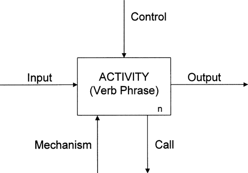
1. A box is named by an active verb or verb phrase.
2. A box has a number (1 to 6), which appears in its lower-right corner.
3. Input is converted by the activity to produce the output, under the direction of the control information.
4. Each of the four sides of the box may have one or more arrows, with the following meaning:
• Arrows entering the left side of the box indicate input.
• Arrows leaving the right side of the box represent output.
• Arrows entering the top of the box show control.
• Arrows entering the bottom of the box indicate mechanism, that is, the what and how of enterprise activity.
• Arrows leaving the bottom of the box are call arrows, which indicate where to look for further detail about the activity.
5. Each arrow segment may be labeled with a noun or noun phrase that describes the contents of the arrow.
In SADT, the space outside and below the lower-right corner of the box is used to show where further detail may be found about the activity represented by the box. This convention was not adopted in the IDEFO standard, but I do use it throughout this book to show that a decomposition exists, or to indicate where to look else-where for more detail (a document, military standard, or other model, for example). In practice, however, the convention changes depending on which software modeling tool is being used to develop the IDEFO model.
The SADT convention for showing that an activity is decomposed is to write a number just below the right side of the box. This number is the C-number, the sequential identifier of the diagram that appears in the lower-right corner of the diagram form. We will see later in this book how this location is used to indicate other forms of links to other models or documents that provide further detail about the activity.
Arrow Syntax Elements
The following rules apply to arrow syntax.
1. Arrows are drawn horizontally or vertically.
2. Curved arrows have corners rounded at a 90 degree arc.
3. Each arrow must have a label describing its content, and this label must be unique throughout the entire model.
4. Arrows that attach to a box at both ends on a single diagram are called internal arrows.
5. Arrows having one end unattached to any box on a single diagram are called boundary arrows, since they represent things entering or leaving the context of that diagram.
6. Arrows having one end unattached at the top-most diagram (called the A-0 diagram) are external arrows, since they represent things entering or leaving the context of the whole model.
Figure 4-2 illustrates the shapes of these arrows.
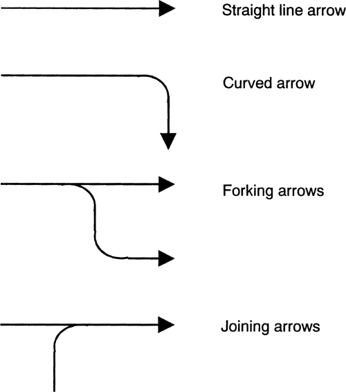
Figure 4-3 shows that arrows can be conduits for other arrows, which may, in turn, contain other arrows. At the top levels of an IDEFO model, these conduits are large bundles of arrows that match the level of abstraction of the high-level activity boxes. As the model is decomposed, forking arrows break out of the larger conduit and feed to the appropriate activity boxes. Likewise, the precise arrow content produced by an activity box, shown leaving the box, bundles with other arrows to form a new conduit.

Arrows that fork from a conduit or join into multiple branches indicate that all data contained in the main branch may flow through all branches. If not all of the content flows through, a restrictive label must be added on the subsidiary branch. Figure 4-3 gives an example: The name Writing Instruments appears on the main branch of the arrow (see the upper right illustration in Figure 4-3), but the Pencils label, written on the branch, shows that only pencils flow in the branch.
We now have defined the basic elements of an IDEFO diagram—boxes and arrows. To form a diagram, we lay out three to six activity boxes in a stairstep fashion on a diagram form, and then add the arrows representing the interfaces between the boxes. Together, these depict the complete story told by the diagram.
The three-six rule (“No diagram shall have fewer than three or more than six boxes”) has great significance in fulfilling the communication power requirement for IDEFO. That is, if fewer than three activities are included in a breakdown, it provides too little new information to be worthwhile; if more than six activities are in the breakdown, then the story is too complex to be conveyed well. The three-six rule has another significant benefit: It results in diagrams that can be copied on a standard 8 ½″ x 11″ sheet of paper. Since one of the basic procedures of IDEFO is the reader/author critique, this ability to copy and distribute models is critical to the method’s practicality.
The IDEFO Diagram Form
Figure 4-4 shows the IDEFO diagram form. Divided into three full-width horizontal sections, the form consists of a temporary working information region (top), a message region (center), and an identification region (bottom). The boxes and arrows are drawn in the message region; the diagram’s position in the model hierarchy is recorded in the identification region, and the temporary working information (such as, project and author names, creation date, level of approval, and revision history) is recorded in the top region. Once the model is ready for publication, this top region, containing temporary information, can be removed, since it is no longer of interest.

The identification region is further divided into three parts containing three types of information: the node number, which gives the position of the diagram in the model structure; the name of the diagram, which must be identical to the box that is being decomposed on the parent diagram; and the diagram number, which identifies the specific sheet of paper. If several different versions of a diagram are created, each will have the same node number and the same name, but each will carry a unique identification number in the lower right-hand corner of the diagram.
The diagram number is typically composed of either the author’s C-number (his initials, followed by the next number of a numerical sequence) or the page number on which the diagram is printed in the final distributed document. The C-number is used while the model is being developed and is assigned by the author each time he starts a new diagram for any purpose. This convention is important for record-keeping purposes and to assure proper configuration management over the model master copy.
The C-number may be figured manually or it may be automatically increased to the next number in the author’s diagram log. Originally, the diagram log was a paper log, but in most cases now, the log is automated through the use of software modeling tools that automatically assign a new number each time the author calls for a blank diagram. The C-number convention originated in SADT, but it was not adopted when the Air Force initiated IDEFO.
The author uses the message region in the center of a second copy of the form to write text about the diagram. When the diagram is finished and published, the text form accompanies the diagram on a facing page, so the reader can study the diagram and text simultaneously, without flipping pages.
The diagram text is not written until the diagram itself has become stable. This occurs late in the reader/author review cycle, when the system experts have validated the diagram, and when the diagram is no longer likely to be changed significantly.
The purpose of the diagram text is to highlight features of the diagram and to facilitate correct presentation of the facts, but all information must be contained on the diagram itself. The text is not intended to expand on the information given in the diagram, nor should it describe what each activity box on the diagram represents—this latter job belongs to the decomposition diagram, as we will see below.
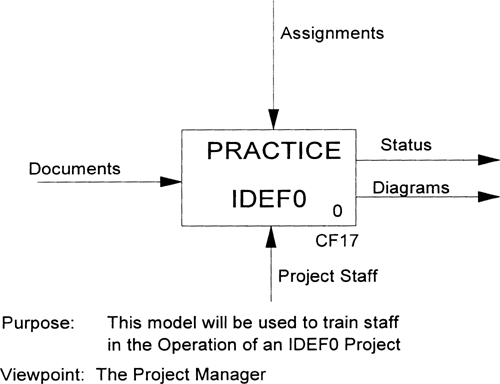
Figure 4-5 depicts the process of authoring IDEFO models and is used here to illustrate the general structure of a diagram in final publication format. The diagram in Figure 4-5 contains five boxes (conforming to the three-six rule), with a verb phrase inside each box describing one activity. These five sub-activities make up the single activity PRACTICE IDEFO. The diagram displays a typical structure of branching and joining arrows, showing interfaces between activities. As was noted earlier in this chapter, arrows that are connected to boxes at both ends are internal to the diagram; arrows with one unconnected end are boundary arrows, whether or not they are coming from or going to the external environment of the diagram.

In Figure 4-5, control arrows entering the tops of boxes show assignments, reminders from the librarian, and approval status. An arrow join is shown near the left side of box 2, where documents and notes join to provide the primary input to the authoring process. A fork is shown in the same area, where the arrow mechanism labeled Authors forks and is shown performing both interviewing (box 1) and authoring (box 2) activities. As you read this chapter, continue to study the diagram for a preliminary view of the process of operating an IDEFO project. We will return to this figure later, after we’ve completed the description of the modeling process.
Earlier in this chapter, we saw how the text form and the diagram represent the same information in the published model. Copies of the same form may also be used to record two additional kinds of information: glossary entries and for-exposition-only (FEO) diagrams.
The glossary that accompanies a diagram defines the box names and arrow labels used on that diagram. Once a model is finished and ready for publication, glossaries for individual diagrams are merged into a single, large glossary for the entire model. An FEO diagram can be attached to a diagram to emphasize some particular fact that furthers the purpose of the model. A typical FEO might contain a copy of the diagram with the main path of arrows highlighted, a particular subset of the diagram describing a critical event, or a raveled-rope picture of the contents of an arrow conduit showing all the individual arrows conveyed by a large pipeline.
IDEFO Model Rules
Now that we have defined the full set of IDEFO diagram rules, let us look next at the rules for IDEFO models. We know that IDEFO models are comprised of diagrams that are integrated into a top-down, hierarchical structure, as shown in Figure 4-6 (seen earlier at Figure 3-2).
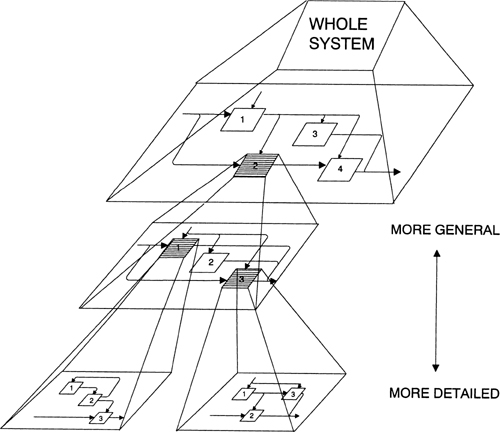
Each diagram represents the breakdown, or decomposition, of a box in the next higher, or parent, diagram level. If a reader wishes to explore details of any element of the system, he may select a diagram, a box on that diagram, the decomposition of the box, a box on that decomposed diagram, and so on, until he reaches the needed level of detail.
The top-most box in a model has box number 0. It appears on a diagram form all by itself and represents the entire system. The diagram for this box has the node number A-0 (pronounced “A minus zero”), where the A signifies an activity model, and the “minus sign zero” signifies the top of the model. The purpose and viewpoint of the model are also recorded as textual annotations on this top-most diagram, since they apply to the entire model. (See Figure 4-7.)
The structure of a model is defined and referenced by node numbers. Each box in the model is a node in the model structure and has a unique node number. If a diagram is decomposed to reveal greater detail, then that new diagram has the same node number as its parent box. To determine the new box’s node number, simply append the box number (which is between one and six) to the diagram’s node number.
The decomposition diagram that shows the first-level breakdown of the top box is called AO (pronounced “A zero”). Each of the up to six boxes on this diagram is then numbered 1 up to 6, from upper left to lower right. The decomposition diagram of each of these boxes is thus numbered Al, A2, on up to A6.
Figure 4-8 shows this structure graphically in the form of a node diagram. The node diagram is often used as a table of contents for an IDEFO model. It is very useful for scanning the breadth and depth of the entire model and then for selecting specific diagrams to examine more closely.
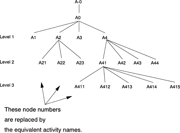
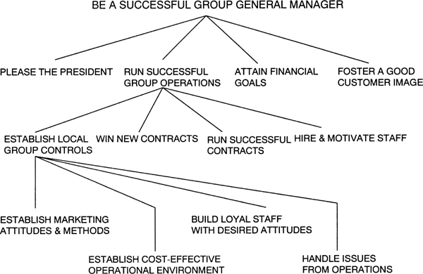
Figure 4-8 shows the pattern of node numbers at each level of detail of a model. If this were an actual node diagram, the name of the box would appear instead of the node number, since the activity name is the item of interest. Figure 4-9 (seen earlier as Figure 2-4) shows how names would be substituted to create an actual node diagram. (Node diagrams are discussed more fully in Chapter 5.)
We have stated that a node number identifies a specific box or diagram in the model. However, a more complete reference language is needed to enable an author who is writing, say, glossary definitions or intermodel references to refer to a specific box, arrow, or arrow segment. This language, called the “model reference language,” permits the author to identify specific input, control, output, or mechanism arrows by means of a code, as follows: Numbering clockwise around the outside of a box and assigning a letter according to the referenced side (I for input, C for control, O for output, and M for mechanism, or ICOM for short), the author defines the referenced side of the box. The arrow head or tail is then further identified by numbering left-to-right and top-to-bottom. This results in a two-character identifier of the form “letter digit” (for example II, C2, or Ml), which totally describes the arrow’s position relative to the box, without requiring the author to write anything more on the diagram. Figure 4-10 illustrates the approach.

By combining the node-numbering language for identifying a box or diagram with ICOM-coding language for identifying a specific arrow head or tail, we now have a very concise textual language for defining any precise spot in an IDEFO model.
The most common use of this reference language is in a detailed reference expression (DRE) to refer to remote diagram locations in a model.
Because IDEFO was created as a high-level method for modeling and analyzing complex systems, it does not contain specific syntax and semantics for particular forms of design solutions. (For example, real-time systems require careful analysis of code timing, which is not part of the general-purpose IDEFO syntax.) IDEFO does have a special syntax designed to point to where the reader may look for further detail. This syntax is indicated at the bottom of the IDEFO box, which is called the “mechanism side.” The mechanism syntax and call-arrow syntax provide precise links between the functional and design models, but also serve the more general purpose of linking the model to other models or to other methods.
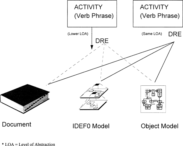
The standard way to link an IDEFO box to another method is by means of the DRE syntax, which appears outside the box, at the lower-right corner of the box (see Figure 4-11).

If a textual expression is written in this position, it tells the reader, “Look here for further detail.” This further detail may be contained in a company document describing the detailed process identified in the IDEFO box, a military standard, the design of a mechanism that performs the function of the box, and so on. The author is encouraged to use the best, most helpful method at each step, with IDEFO providing the high-level glue that integrates the entire system description.
The DRE is made up of two fields, with a dot character separating the two. To the left of the dot, the node-numbering language identifies the diagram; to the right of the dot, the box number and ICOM code specify a point on the diagram. Figure 4-12 illustrates how DREs are used.
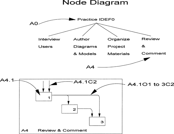
The node diagram shown at the top of Figure 4-12 identifies A4 Review & Comment as the diagram of interest. Diagram A4 appears as an inset below the node diagram, and illustrates specific DREs: If we wish to refer to box 1 on diagram A4, we write “A4.1.” If we wish to refer to the second control arrow entering box 1 on diagram A4, we write “A4.1C2.” To refer to the branch of the arrow that leaves box 1 and controls box 3 on diagram A4, we write “A4.1O1 to 3C2.” Note that the form “A4.1O1 to 3C2” refers to the arrow branch that controls box 3, not to the branch that controls box 2. If we wish to refer to the entire arrow instead of to a single branch, we write “A4.1O1,” that is, without the qualifier “to 3C2.”
DREs are used to link boundary arrows between diagrams within a model and between different models. They are also used wherever a concise notation is needed to refer to an item of interest in a model or diagram (such as in text or in FEO diagrams).
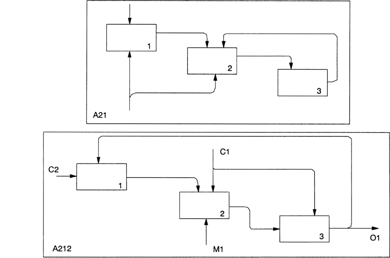
To link boundary arrows, a modeler annotates the lower level, or child, diagram’s boundary arrows by writing the ICOM code near the unconnected end of each boundary arrow. The ICOM code refers to the position at which the boundary arrow enters or leaves the parent box from which the child diagram is decomposed. The concept is illustrated in Figure 4-13, which shows box 2 of diagram A21 (top of the figure) and its decomposition into three sub-activities in diagram A212. Two controls, one output, and one mechanism are depicted as interfaces between the child diagram and the parent box.
We have now discussed diagrams and models, including levels of detail within a model, but our discussion has not addressed the arrows used on the bottom side of the IDEFO activity box—the mechanism side. (See Figure 4-14.)

The primary use of the mechanism side is to show the boundary between the what and the how of enterprise activities. The mechanism side permits the analyst to consider alternative ways of implementing improvements on existing enterprise activities. Performing what is commonly called “what if” analysis, the analyst can use the mechanism to suggest a way to automate a manual process, an analysis of alternative methods at different enterprise divisions, a change in the organization structure that uses different personnel to perform an activity, an introduction of new equipment, and a variety of other what/how possibilities.
Arrows entering or leaving the bottom of the activity box indicate interfaces with the next lower level of mechanization and may be either “mechanism” arrows or “call” arrows. The entering—or mechanism—arrow represents the combination of people, equipment, and computer software that perform the activity named in the IDEFO activity box (see Figure 4-15). The leaving—or call—arrow indicates where to look for additional detail about the activity.
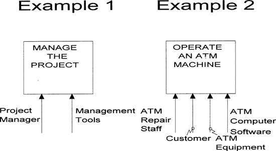
Let us first look at how the mechanism arrow functions. As we have stated, a mechanism arrow enters the bottom of the activity box. The name of the mechanism is written alongside the arrow and may be attached to the arrow by a squiggle. There is only one mechanism name per mechanism arrow, but this name may be used to designate a set of mechanisms, such as a tool set. If more than one mechanism arrow is shown entering the box, the activity is performed by a combination of the people, equipment, and software shown on the arrows (see Figure 4-15).
The set of mechanism arrows may represent how a portion—but not all—of the activity is performed. For example, the mechanism arrows included in an IDEFO model may represent an organization, but not its equipment or computer software; this may indicate that organizational responsibility is an aspect that must be further analyzed to fulfill the purpose of the model. Or, if the support mechanisms themselves are a focus, then the equipment or computer support systems may be shown on the arrows—without showing the organizational responsibility. In a pure functional model, neither type of mechanism needs to be shown. Mechanism arrows may branch or join, just like any other IDEFO arrow. A mechanism arrow branch indicates which mechanisms are used by which activities on the decomposition diagram. (See Figure 4-16.)
As we have seen, there is a second type of arrow used at the mechanism side of an activity box—the call arrow, which leaves the bottom of the box and points in the opposite direction of the mechanism arrow (see Figure 4-17). The call arrow represents a break in the activity decomposition structure, and the name written alongside the call arrow indicates where further detail about the activity can be found. For example, the call arrow might indicate a paragraph or page number in a document (such as a military standard or a company’s operating procedures manual), or it may point to a full-blown IDEFO model or to an activity box in another IDEFO model that provides detail about the activity.
In practice, an IDEFO author occasionally comes upon an activity that was previously encountered in the course of decomposing a parent activity. For example, two different offices may share technical publications support, a copy service, a facilities maintenance staff, and so on. These identical activities need not be modeled redundantly. Likewise, their diagrams need not be copied and reproduced multiple times in the model decomposition. Instead, the diagrams representing the redundant activity are placed in a separate model and then referenced via a call arrow at each point in the main model where the parent activity occurs (see Figure 4-18). This structure is called a many-to-one structure join, since many calls reference one model.
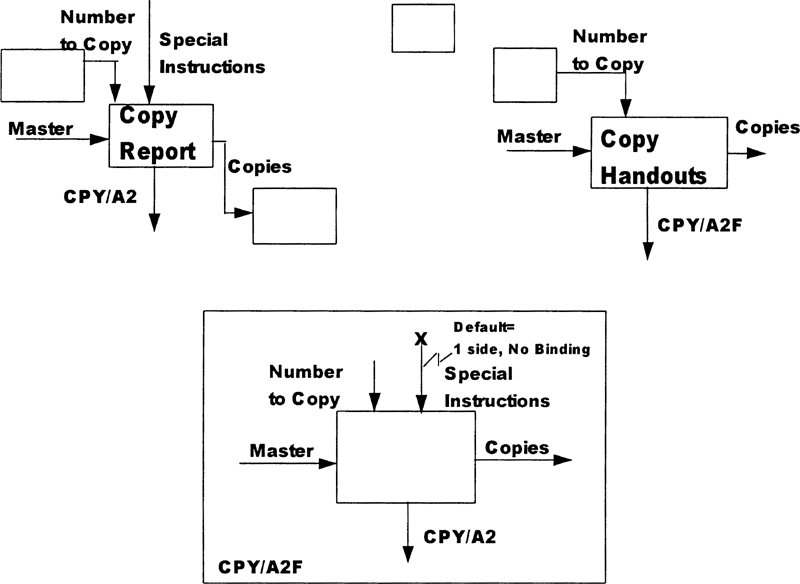
In the simplest situation, the arrows entering and leaving all caller boxes are identical in number. However, this may not always be the case. That is, one or more called boxes may have a different number of input, control, or output arrows. An additional arrow most frequently indicates a parameter in the call that has an assumed or default value in the other cases. This parameter may be specified in the model by making the call arrow reference a different A-0 (single box) diagram than the actual top of the common model. The intervening A-0 diagram documents the difference between the additional arrow and the normal call by showing any additional arrows (with their default values listed in a label alongside the arrow) and an X at the unconnected end of the arrow (to indicate that it may not appear in the calling box). See Figure 4-19.
The split-by-type (SBT) structure shown in Figure 4-20 represents a one-to-many split—just the opposite of the previous case. That is, a single box in a decomposition calls one of a set of many equivalent activities at a lower level of abstraction. This event could be modeled as a normal child diagram, except the breakdown is not a decomposition but, rather, is an SBT structure.
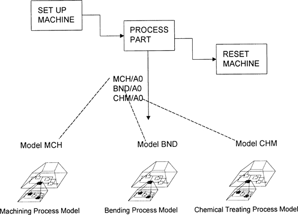
Many examples of SBT occur in modeling business processes. In a manufacturing operation, for example, the point at which a manufacturing process is applied to a part is such an instance. Instead of modeling how all forms of processing are done (decomposing the verb “process”), the author decides that it would be more helpful to talk about different types of processes (see Figure 4-20).
In such a case, the author would list multiple target models alongside the call arrow to indicate that any of these activities may occur at this point in the processing, depending on the content of one or more of the input or control arrows. In the manufacturing example just cited, this might be the list of instructions to the machine operator or robot, indicating which process to apply in what order.
The call arrow stems from a computer programming practice in which a subroutine may be called by a main program to accomplish a task. For example, a call might be made to a file read/write package to write a record onto a disk. The read/write package is the mechanism, whereas the write subroutine piece of the package is called to write a specific record onto the disk.
In computer programming, the subroutine call has the same effect as if the instructions in the subroutine were included at the point of the call. Since the call may occur at several locations in the main program, the size of the program’s code is reduced by eliminating the need for repeating the instructions at each call location. This is analogous to the call arrow in IDEFO, in that the activity box represents the subroutine call, and the called model or document is equivalent to the entire body of the called model or document at the point of the call.
A call arrow is used at a lower level of detail than a mechanism arrow. That is, a mechanism arrow indicates that the mechanism is used to perform one or more of the sub-activities, sub-sub-activities, and so on, of the parent box on which the mechanism arrow appears. A call arrow, on the other hand, represents a precise call to a unique activity box or other form of description that matches the activity precisely. Thus, there can only be one call arrow leaving an IDEFO box, whereas there may be many mechanism arrows entering the same box.
As we have said, a mechanism arrow may represent a person or a group of people (that is, a lone manager or the entire department staff, for example), a machine (for example, a PC or a machine tool), or a support system (a word processor, a spreadsheet system, or the like). However, since a person or machine cannot precisely match an activity, only an element of a “person,” “machine,” or “support system” mechanism may appear on a call arrow. Looking at the issue another way, we might say that a called activity represents a mechanism view (the how) of the functional description (the what) represented by the caller activity box.
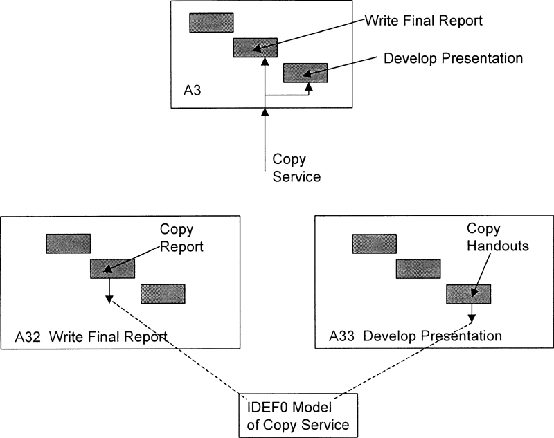
In particular, a mechanism arrow for a software support system may be related to one or more call arrows, since the mechanism arrow may indicate general support at a higher level of detail in an IDEFO model, and then may identify precise subsystem calls to the more detailed levels. These calls may or may not appear, depending on whether the IDEFO model is decomposed into fine enough detail to identify specific calls. By looking again at Figure 4-18, we can see the Copy Service mechanism supporting diagram A3. The decomposition of A3 shows the copy service mechanism branching to support two sub-activities: Write Final Report (A32) and Develop Presentation (A33). The decomposition of these two activities then shows explicit calls on the copy service model from A322 and A333 for obtaining report and handout copies, respectively.
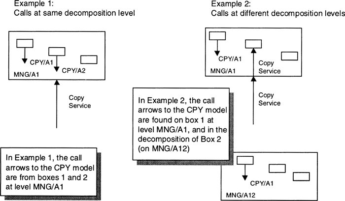
Figure 4-21 shows the mechanism- and call-arrow structure for the general-level mechanism and its corresponding calls at the detailed level. Of course, many variations are possible. There may be several levels of mechanism arrow structure before any calls appear; or there may be call and mechanism arrows that appear at the same level.
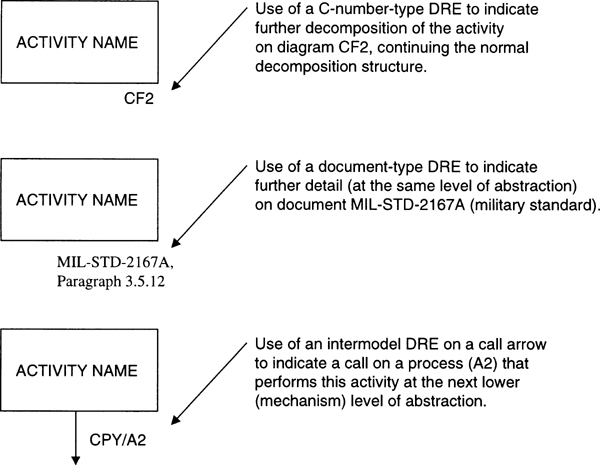
Now that the role of the call arrow has been described, there may be a question as to the use of the call arrow versus the DRE, which is written below the right-hand corner of the activity box to indicate that further detail exists. The basic difference is that the DRE indicates that further detail exists at the same level of mechanization as the parent box, whereas the call arrow indicates a drop in the level of mechanization (from the functional level to the mechanism level). Figure 4-22 illustrates the difference.
Recall that, in the previous example of redundant calls on the copy service, the use of a call arrow was correct, since this is a drop in level of mechanization (between the main operation of the office and the operation of the copy support service). If the redundant activity boxes had been at the same level of mechanization (two or more identical activities at the same office operations level), then a DRE below the right-hand side of the activity boxes referencing a model of the activity would have been correct (with no use of the call arrow, since a drop in level of mechanization is not indicated).
In the following chapter, we apply what we know about the syntax and semantics of IDEFO to a higher level of modeling: pragmatics, or the way we create an IDEFO model.